

Page 1

www.lg.com
INSTALLATION MANUAL
AIR CONDITIONER
• Please read this installation manual completely before installing the product.
• Installation work must be performed in accordance with the national wiring
standards by authorized personnel only.
• Please retain this installation manual for future reference after reading it
thoroughly.
TYPE : Independent Power Kit (for Multi V Product)
MODEL : PRIP0
P/NO : MFL65920002
Page 2
2 Independent Power Kit
IMPORTANT!
Please read this instruction sheet completely before installing the product.
This air conditioning system meets strict safety and operating standards. As the installer or service person,
it is an important part of your job to install or service the system so it operates safely and efficiently.
WARNING
• The information contained in the manual is intended for use by a qualified service technician familiar with safety
procedures and equipped with the proper tools and test instruments.
• Failure to carefully read and follow all instructions in this manual can result in equipment malfunction, property
damage, personal injury and/or death.
CAUTION
Safety Precautions
NOTE TO INSTALLING DEALER: The Owners Instructions and Warranty are to be given to the owner
: Improper installation, adjustment, alteration, service or maintenance can void the warranty.
The weight of the condensing unit requires caution and proper handling procedures when lifting
or moving to avoid personal injury. Use care to avoid contact with sharp or pointed edges.
• Always wear safety eye wear and work gloves when installing equipment.
• Never assume electrical power is disconnected. Check with meter and equipment.
• Keep hands out of fan areas when power is connected to equipment.
• R-410A causes frostbite burns.
• R-410A is toxic when burned.
or prominently displayed near the indoor Furnace/Air Handler Unit.
When wiring:
Electrical shock can cause severe personal injury or death. Only a qualified,
experienced electrician should attempt to wire this system.
• Do not supply power to the unit until all wiring and tubing are completed or reconnected and checked.
• Highly dangerous electrical voltages are used in this system. Carefully refer to the wiring diagram and these
instructions when wiring. Improper connections and inadequate grounding can cause accidental injury or death.
• Ground the unit following local electrical codes.
• Connect all wiring tightly. Loose wiring may cause overheating at connection points and a possible fire hazard.
When transporting:
Be careful when picking up and moving the indoor and outdoor units. Get a partner to help, and
bend your knees when lifting to reduce strain on your back. Sharp edges or thin aluminum fins on
the air conditioner can cut your finger.
When installing...
... in a wall: Make sure the wall is strong enough to hold the unit's weight.
... in a room: Properly insulate any tubing run inside a room to prevent "sweating" that can cause
... in moist or uneven locatinons: Use a raised concrete pad or concrete blocks provide a solid,
... in an area with high winds: Securely anchor the outdoor unit down with bolts and a metal
... in a snowy area(for Heat Pump Model): Install the outdoor unit on a raised platform that is
When connecting refrigerant tubing
• Keep all tubing runs as short as possible.
• Use the flare method for connecting tubing.
• Check carefully for leaks before starting the test run.
When servicing
• Turn the power OFF at the main power box(mains) before opening the unit to check or repair
electrical parts and wiring.
• Keep your fingers and clothing away from any moving parts.
• Clean up the site after you finish, remembering to check that no metal scraps or bits of wiring have
been left inside the unit being serviced.
It may be necessary to construct a strong wood or metal frame to provide added support.
dripping and water damage to wall and floors.
level foundation for the outdoor unit. This prevents water damage and abnormal vibration.
frame. Provide a suitable air baffle.
higher than drifting snow. Provide snow vents.
WARNING
Page 3

Installation Manual 3
Independent Power Kit INSTALLATION MANUAL
TABLE OF CONTENTS
1. Safety Precautions ............................................................................................................4
2. Included Items....................................................................................................................5
3. Applied model ....................................................................................................................6
4. Piping Installation..............................................................................................................7
5. Assembly Diagram ............................................................................................................8
6. Electrical Wiring...............................................................................................................15
Page 4
4 Independent Power Kit
To prevent injury to the user or other people and property damage, the following instructions
must be followed.
n Incorrect operation due to ignoring instruction will cause harm or damage. The seriousness
is classified by the following indications.
1. Electric works should be carried out according to ʻThe technology requirement on the
electric installationʼ, The wiring standard and this manual by a qualified personnel.
2. If the installation is not complete or the capacity of the power circuit is insufficient, electric
shock or fire may occur, or death or injury can be caused.
3. If the installation was done by a user, there may be incompleteness, which may cause
electric shock, fire, injury and death.
4. When operating the machine (applying power to the machine), do not carry out any electric
work and do not put hand or finger into it. This may cause electric shock, injury and death.
n Meanings of symbols used in this manual are as shown below.
WARNING
CAUTION
This symbol indicates the possibility of death or serious injury.
This symbol indicates the possibility of injury or damage.
Be sure not to do.
Be sure to follow the instruction.
WARNING
1. Before installation, read this manual and carry out the works according to it.
2. Before installation, be sure to check all the included items. (However, be sure to use all
kinds of certified products when purchasing the items other than those provided by LG at
your local store.)
CAUTION
1. Safety Precautions
1. Safety Precautions
Page 5
Installation Manual 5
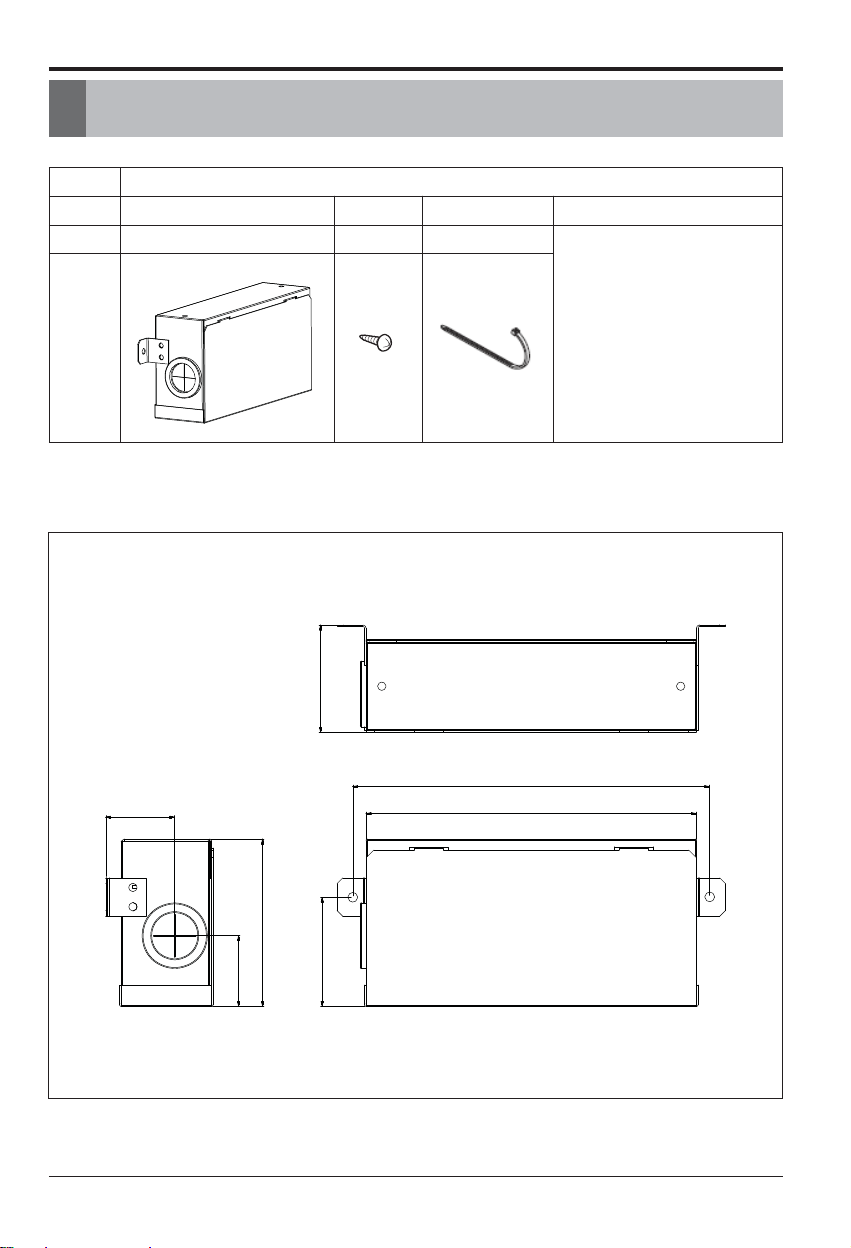
2. Included Items
(Unit : mm)
2. Included Items
Model
PRIP0
Item Independent Power Kit Screw
Clamp (Tie Wrap)
(Other)
Qʼty 1 2 4
• Harness 1(1m)
• Harness 2(1m)
• Harness 3(1m)
• Installation manual
• Insulation (PE)
Figure
M4 x 10
56
185
36
87
57
37
175
Page 6

6 Independent Power Kit
3. Applied model
3. Applied model
Wall Mounted
ART COOL Mirror
Ceiling Cassette- 1Way
Ceiling Cassette- 4Way
Ceiling & Floor
Ceiling Suspended
ARNU07GTU*2
ARNU09GTU*2
ARNU12GTU*2
ARNU05GTR*2
ARNU07GTR*2
ARNU09GTR*2
ARNU12GTR*2
ARNU15GTQ*2
ARNU18GTQ*2
ARNU24GTP*2
ARNU28GTP*2
ARNU36GTN*2
ARNU42GTM*2
ARNU48GTM*2
Ceiling Concealed Duct - Low Static
ARNU07GB1G2
ARNU09GB1G2
ARNU12GB1G2
ARNU15GB1G2
ARNU18GB2G2
ARNU24GB2G2
ARNU07GSE*2
ARNU09GSE*2
ARNU12GSE*2
ARNU15GSE*2
ARNU18GS5*2
ARNU24GS5*2
ARNU07GSE*2
ARNU09GSE*2
ARNU12GSE*2
ARNU15GSE*2
ARNU18GS8*2
ARNU24GS8*2
ARNU09GVEA2
ARNU12GVEA2
URNU18GVJA2
URNU24GVJA2
URNU36GVKA2
URNU48GVLA2
Console
ARNU07GQAA2
ARNU09GQAA2
ARNU12GQAA2
ARNU15GQAA2
HYDRO KIT
ARNH10GK2A2
ARNH05GK2A2
ARNH08GK3A2
ARHN05GK3A2
Floor Standing
With case
ARNU07GCEA2
ARNU09GCEA2
ARNU12GCEA2
ARNU15GCEA2
ARNU18GCFA2
ARNU24GCFA2
Without case
ARNU07GCEU2
ARNU09GCEU2
ARNU12GCEU2
ARNU15GCEU2
ARNU18GCFU2
ARNU24GCFU2
Ceiling Concealed Duct - High Static
ARNU07GBHA2
ARNU09GBHA2
ARNU12GBHA2
ARNU15GBHA2
ARNU18GBHA2
ARNU24GBHA2
ARNU28GBGA2
ARNU36GBGA2
ARNU42GBGA2
ARNU48GBRA2
URNU76GB8A2
URNU96GB8A2
Ceiling Concealed Duct – Built-in
ARNU07GB3G2
ARNU09GB3G2
ARNU12GB3G2
ARNU15GB3G2
ARNU18GB4G2
ARNU24GB4G2
* A:Basic, L:Plasma
ART COOL Gallery
ARNU07GSF*2
ARNU09GSF*2
ARNU12GSF*2
* E:Red V:Silver
G:Gold 1: Kiss (Photo changeable)
* A:Basic, C:Plasma
* R:Mirror, V:Silver, B:Blue
ARNU18GTT*2
ARNU24GTT*2
* A:Basic, C:Plasma
Ceiling Cassette -2Way
ARNU18GTL*2
ARNU24GTL*2
* A:Basic, C:Plasma
Fresh Air Intake Unit
ARNU48GBRZ2
ARNU76GB8Z2
ARNU96GB8Z2
Page 7

4. Piping Installation
Installation Manual 7
4. Piping Installation
The pipes between a indoor unit connected PRIP0 and its branch must maintain to incline
preventing a back flow toward the indoor unit as shown below. Otherwise, the unit may not
operate properly.
If the indoor unit is located lower than its branch, apply Oil Trap as shown below. Otherwise,
the unit may not operate properly.
H H H
A
H = 0.1 m or more
A = 2 m or less
H = 0.1 m or more
A = 2 m or less
A
H
H
H
H = 0.1 m or more
A = 2 m or less
H< 0.1 m
A >2 m
A
A
A
A
H
H
H
H
H
Page 8

8 Independent Power Kit
5. Assembly Diagram
14
L
Fig. A
Control box cover
screw
Insulation
5. Assembly Diagram
n High Static Duct/FAU
Note: While connecting the PRIP0, attach insulation at the rear of the control box cover
where it receives screws as shown in Fig. A.
Check the distance between PRIP0 and a control box when
connecting anchor bolts.
Step1. Open control box cover. Step2. Assemble PRIP0 with control box cover.
Step3. Open the cover of PRIP0 and connect wires. Step4. Assemble control box cover.
Assembly Diagram - PRIP0
CAUTION
chassis L
BH 1,090
BG 1,350
BR 1,400
B8 1,720
(Unit : mm)
Page 9

5. Assembly Diagram
Installation Manual 9
n Low Static Duct/Built-in Duct
112
L
Fig. A
Control box cover
screw
Insulation
Note: While connecting the PRIP0, attach insulation at the rear of the control box cover
where it receives screws as shown in Fig. A.
Step1. Open control box cover. Step2. Assemble PRIP0 with control box cover.
Step3. Open the cover of PRIP0 and connect wires. Step4. Assemble control box cover.
(Unit : mm)
CAUTION
Check the distance between PRIP0 and the top of model
when connecting anchor bolts.
chassis L
B1/B3 1,090
B2/B4 1,350
Page 10

10 Independent Power Kit
5. Assembly Diagram
n 1 Way CST
Step1. Open control front panel. Step2. Assemble PRIP0 with cabinet.
Step3. Open the cover of PRIP0 and connect wires. Step4. Assemble control box cover and front panel.
Fig. A
Control box cover
screw
Insulation
Note: While connecting the PRIP0, attach insulation at the rear of the control box cover
where it receives screws as shown in Fig. A.
L
chassis L
TU/TT 510
(Unit : mm)
Page 11

5. Assembly Diagram
Installation Manual 11
n 2 Way CST
Step1. Open control front panel. Step2. Assemble PRIP0 with cabinet.
Step3. Open the cover of PRIP0 and connect wires. Step4. Assemble control box cover and front panel.
Fig. A
Control box cover
screw
Insulation
Note: While connecting the PRIP0, attach insulation at the rear of the control box cover
where it receives screws as shown in Fig. A.
L
chassis L
TL 890
(Unit : mm)
Page 12

12 Independent Power Kit
5. Assembly Diagram
n 4 Way CST
L
Step1. Open control front panel. Step2. Assemble PRIP0 with cabinet.
Step3. Open the cover of PRIP0 and connect wires. Step4. Assemble control box cover and front panel.
CAUTION
Fig. A
Control box cover
screw
Insulation
Note: While connecting the PRIP0, attach insulation at the rear of the control box cover
where it receives screws as shown in Fig. A.
Check the attached direction to the indoor unit.
chassis L
TQ/TR 630
TP/TN/TM 900
(Unit : mm)
Page 13

5. Assembly Diagram
Installation Manual 13
n Ceiling Suspended/Console
D < 1000 mm
Wall
Wall
Pipe
Step1. Mount relay kit on the wall. Step2. Connect wires (use a piping or wiring hole) and
assemble cover.
Do not install PRIP0 at places exposed to rain or any water.
Other wise it may leads to electric shock, fire, injury or sometimes even fatality.
Independent power kit should be installed within 1000mm which is length of the given wires.
Otherwise Indoor EEV may cause malfunction.
CAUTION
CAUTION
Page 14

14 Independent Power Kit
5. Assembly Diagram
n Wall mounted & Art cool
D < 1000 mm
Step1. Mount relay kit on the wall.
Step2. Connect wires (use a piping or wiring hole) and
assemble cover.
Step 1. Open the front panel of the control box.
Step 2. Assemble the cover of PRIP0, fix it tightly with bolts
and connect wires.
CAUTION
CAUTION
Do not install PRIP0 at places exposed to rain or any water.
Other wise it may leads to electric shock, fire, injury or sometimes even fatality.
Independent power kit should be installed within 1000mm which is length of the given wires.
Otherwise Indoor EEV may cause malfunction.
n Hydro Kit
Page 15

6. Electrical Wiring
Installation Manual 15
6. Electrical Wiring
DUCT/FS/CVT/FAU CST/Console/Hydro Kit Wall mounted/ ART COOL
To Indoor unit’s EEV
To Indoor unit’s EEV
To Indoor unit’s EEV
EEV
EEV
EEV
CN_WRITE
CN_EEV
CN_EEV/MAIN
CN_EEV/LOAD
CN_EEV/MAIN
CN_EEV/LOAD
CN_EEV/MAIN
CN_EEV/LOAD
Harness 1Harness 1Harness 1
Harness 2
Harness 2Harness 2
Harness 1
Harness 1Harness 1
Harness 2
Harness 2Harness 2
Harness 1
Harness 1Harness 1
Harness 3
Harness 3Harness 3
CN_WRITECN_WRITECN_WRITE
CN_EEVCN_EEVCN_EEV
CN_WRITECN_WRITECN_WRITE
CN_EEVCN_EEVCN_EEV
• The wire should not be exposed to the outside otherwise it may leads to the malfunction
of the independent power kit due to wire damage.
• Wrong wiring also causes the malfunction of the independent power kit or damage to it.
• Power should be supplied more than 20 minutes continuously in order to operate the
independent power kit correctly. Otherwise, the independent power kit can not fully close
the EEV due to the lack of the charging power.
WARNING
1. Turn the power off using circuit breaker.
2. Disconnect the EEV cable of the indoor unitʼs PCB(CN-EEV)
3. Connect the independent power kit(CN-EEV/LOAD) to the indoor unitʼs EEV, using
harness 1.
4. Connect the independent power kit(CN-EEV/MAIN) to the indoor unitʼs PCB(CNEEV/CN-WRITE), using harness 2 or 3.
5. Supply the power.
*FS : Floor Standing
*CVT : Convertible
*FAU : Fresh Air Intake Unit
*CST : Cassette
Page 16

 Loading...