

Page 1

LIMBA ROMÂNĂ
ENGLISH
УКРАÏНСЬКА
中文
РУССКИЙ ЯЗЫК
ČEŠTINA
OWNER’S & INSTALLATION
MANUAL
AIR CONDITIONER
Please read this installation manual completely before installing the product.
Installation work must be performed in accordance with the national wiring standards by authorized personnel only.
Please retain this installation manual for future reference after reading it thoroughly.
WIRED REMOTE CONTROLLER
PREMTW101
MFL69312308
Rev.00_102119
DEUTSCH
ΕΛΛΗΝΙΚΆ
ESPAÑOL FRANÇAIS
ITALIANO
NEDERLANDS
POLSKI
www.lg.com
Copyright © 2019 LG Electronics Inc. All Rights Reserved.
Page 2
TIPS FOR SAVING ENERGY
2
SAFETY INSTRUCTIONS
3
ENGLISH
TIPS FOR SAVING ENERGY
Here are some tips that will help you minimize the power consumption when you use the air
conditioner. You can use your air conditioner more efficiently by referring to the instructions
below:
• Do not cool excessively indoors. This may consume more electricity.
• Block sunlight with blinds or curtains while you are operating the air conditioner.
• Keep doors or windows closed tightly while you are operating the air conditioner.
• Adjust the direction of the air flow vertically or horizontally to circulate indoor air.
• Speed up the fan to cool or warm indoor air quickly, in a short period of time.
• Clean the air filter once every 2 weeks. Dust and impurities collected in the air filter may block
the air flow or reduce the cooling / dehumidifying functions.
For your records
Staple your receipt to this page in case you need it to prove the date of purchase or for warranty
purposes. Write the model number and the serial number here:
Model number :
Serial number :
You can find them on a label on the side of each unit.
Dealer’s name :
Date of purchase :
SAFETY INSTRUCTIONS
The following safety guidelines are intended to prevent unforeseen risks or damage from unsafe
or incorrect operation of the appliance.
The guidelines are separated into ‘WARNING’ and ‘CAUTION’ as described below.
This symbol is displayed to indicate matters and operations that can cause risk.
Read the part with this symbol carefully and follow the instructions in order to avoid
!
risk.
WARNING
!
This indicates that the failure to follow the instructions can cause serious injury or death.
CAUTION
!
This indicates that the failure to follow the instructions can cause the minor injury or damage
to the product.
WARNING
!
Installation
• For electrical work, contact the dealer, seller, a qualified electrician, or an authorized service
Center.
- Do not disassemble or repair the product. There is risk of fire, electric shock, explosion,
equipment malfunction, or injury.
• Request to the service center or installation specialty store when reinstalling the installed
product.
- There is risk of fire, electric shock, explosion, equipment malfunction, or injury.
• Do not disassemble, fix, and modify products randomly.
- There is risk of fire, electric shock, explosion, equipment malfunction, or injury.
• The product shall be installed according to the national standards and local code.
• Apply totally enclosed noncombustible conduit in case of local building code requiring plenum.
• Use appropriate unit mounting procedures.
• Avoid direct sunlight.
• Avoid moist areas.
In-Use
• Do not place flammable objects close to the product.
- There is risk of fire, electric shock, explosion, equipment malfunction or injury.
• Do not allow product to get wet.
- There is risk of fire, electric shock, explosion, equipment malfunction or injury.
• Avoid dropping the product.
- There is risk of fire, electric shock, explosion, equipment malfunction or injury.
Page 3

SAFETY INSTRUCTIONS
4
• If product gets wet, contact your dealer or authorized service center.
- There is risk of fire, electric shock, explosion, equipment malfunction, or injury. If the
instructions are not followed, it may cause death or severe injury of the user.
• Do not use sharp or pointed objects on product.
- There is risk of fire, electric shock, explosion, equipment malfunction or injury.
• Do not touch or pull the lead wire with wet hands.
- There is risk of product breakdown or electric shock.
CAUTION
!
In-Use
• Do not clean using powerful detergents like solvent but use soft cloths.
There is risk of fire, electric shock, explosion, equipment malfunction or deformation.
• Do not press the screen using powerful pressure.
There is risk of product break-down or malfunction.
TABLE OF CONTENTS
2 TIPS FOR SAVING ENERGY
3 SAFETY INSTRUCTIONS
8 DESCRIPTION
8 Remote controller
9 DESCRIPTION OF THE OPERATION
9 Main screen
9 Menu screen
10 Setting screen
10 Popup screen
11 Monitoring
12 Returning to the screen
12 OPERATION SETTING
12 On / Off
12 Operation mode
13 Cooling operation
14 Heating operation
15 AI / Auto operation
16 TEMPERATURE SETTING
16 Controlling desired temperature
17 DHW heating operation
17 Quick DHW tank heating
18 View temperature
20 Zone target temperature
21 LOCK SETTING
21 How to enter Lock setting
22 Lock setting – all, on/off, mode, DHW lock
23 TIMER SETTING
23 Timer entrance and setting method
24 Simple Timer
25 Turn-On Reservation
26 Turn-Off Reservation
27 SCHEDULE SETTING
27 How to enter schedule
28 Daily schedule
29 Schedules & Edit
30 Schedules & Edit – Add schedule
31 Exception Day
TABLE OF CONTENTS
5
ENGLISH
Page 4

TABLE OF CONTENTS
32 INFORMATION OF METER INTERFACE
33 FUNCTION SETTING
33 How to enter function setting
34 Function setting
35 Low Noise Mode Time
36 Wi-Fi Pairing
37 Water Temperature Setting
38 3nd Party Boiler
39 USER SETTING
39 How to enter user setting
39 User Setting
40 Language
41 Temperature Unit
42 Screen Saver Timer
42 LCD Brightness In Idle
43 Date
44 Time
45 Summer Time
46 Password
47 Schedule Initialization
48 Theme
48 System Reboot
49 SERVICE SETTING
49 How to enter service setting
49 Service setting
50 Service Contact
51 Model Information
52 RMC Version lnformation
53 Open Source License
54 INSTALLATION
54 Installation of Remote Controller
56 Group control
59 INSTALLER SETTING
59 How to enter installer setting
60 Installer setting
63 Test Run
64 3 Minutes Delay
65 Select Temperature Sensor
66 Dry Contact Mode
67 Central Control Address
68 Override Master/Slave
69 Pump test run
70 Air cooling set temp
71 Water cooling set temp
72 Air heating set temp
73 Water heating set temp
74 DHW set temp
75 Cooling / Heating only mode
76 Screed drying
78 Heater on temperature
80 Water supply off temp. during cooling
82 Outdoor temp. for auto mode
83 Indoor air temp. for auto mode
84 LWT for auto mode
85 Tank disinfection setting 1, 2
86 Tank setting 1
87 Tank setting 2
89 Heater priority
90 DHW time setting
91 Use Heating Tank Heater
92 Pump frequency setting (LPM)
93 TH on/off Variable, heating air
94 TH on/off Variable, heating water
95 TH on/off Variable, cooling air
96 TH on/off Variable, cooling water
97 Heating temp. setting
98 Cooling temp. setting
99 Pump setting in heating
100 Pump setting. in cooling
101 Forced operation
102 CN_CC
103 Pump Capacity
104 Pump frequency setting (RPM)
105 Smart Grid(SG)
106 Seasonal auto temp
108 Modbus Address
109 Refrigerant Leak Sensor
110 IDU Address Verification
111 CN_EXT
112 ODU Function Master
113 Low Noise Mode Priority
114 Anti-freezing Temperature
115 Add Zone
116 Use External Pump
117 3rd Party Boiler
118 Meter Interface
119 Estimated energy display
120 Pump Prerun/Overrun
121 Solar Thermal System
123 Zone
125 Current flow rate
126 Data logging
127 Password Initialization
128 RMC master/slave
129
NOTICE
129 OPEN SOURCE SOFTWARE NOTICE INFORMATION
TABLE OF CONTENTS
76
ENGLISH
Page 5
DESCRIPTION
8
DESCRIPTION OF THE OPERATION
9
ENGLISH
DESCRIPTION
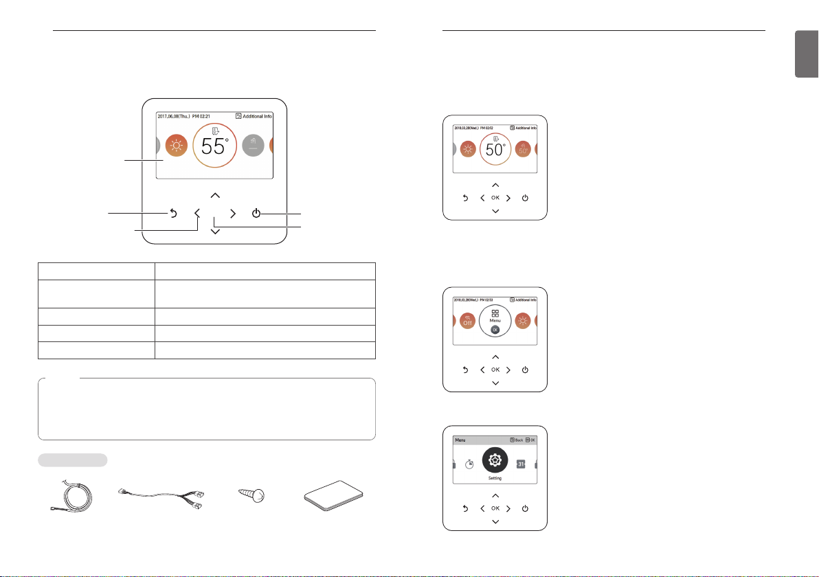
Remote controller
Operation display
window
Back button
Up/Down/Left/Right
button
Operation display window Operation and Settings status display
Back button
Up/down/left/right button
OK button
On/Off button When you turn ON/OFF the air conditioner
When you move to the previous stage from the menu’s
setting stage
When you change the menu’s setting value
When you save the menu’s setting value
NOTE
• Some functions may not be operated and displayed depending on the product type.
• The actual product can be different from above contents depending upon model type.
• When using simultaneous operation system, whenever press remote controller button,
system will approximately operate after 1~2 minutes.
OK
On/Off button
OK button
DESCRIPTION OF THE OPERATION
Main screen
In the main screen, press [<, >(left/right)] button to select the category to set, and you can
control by pressing [∧,∨ (up/down)] button.
Menu screen
In the main screen, press [<, >(left/right)] button to select the menu and press [OK] button to
move to menu screen.
In the menu screen, press [<, >(left/right)] button to select the category to set, and press [OK]
button to move to the detail screen.
Accessories
Connecting Cable 2-Remo cable Remote controller
fixing screws
(4 EA)
Quick Guide
Page 6
DESCRIPTION OF THE OPERATION
10
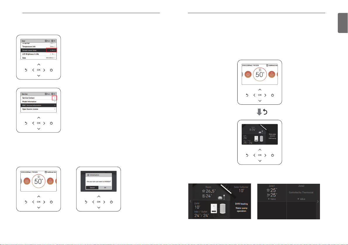
Setting screen
Select the category to set using [∧,∨(up/down)] button.
In each detail screen of the menu, as in the box in the left figure,
when “<,>” icons are displayed at the same time, you can
immediately apply the setting value by pressing [<, >(left/right)]
button.
※ For the values that can be set in each category, refer to the
detail manual for each function.
In each detail screen of the menu, as in the box in the left figure,
if only “>” icon is displayed, you can move to the detail setting
screen by pressing [>(right) or OK] button.
※ For the values that can be set in each category, refer to the
detail manual for each function.
Popup screen
The toast message is the message displayed at the bottom of the screen when an operation is
turned On/Off or if a function is set / cancelled.
The popup message is mainly displayed when an error occurred in the product.
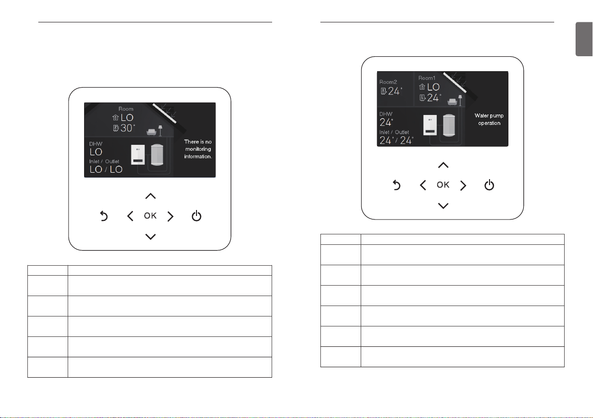
DESCRIPTION OF THE OPERATION
Monitoring
In the main screen, you can enter the monitoring screen by pressing [Back] button
In the monitoring screen, you can check the following information,
- The room temperature
- The water inlet / outlet temperature
- The water pump operation
- The zone status (when set the zone usage via installer setting)
When set the zone usage via installer setting.
11
ENGLISH
< Toast message > < Popup message >
Page 7
OPERATION SETTING
12
Returning to the screen
In the main screen, after moving to the category by pressing [<, >(left/right)] button, if there is no
remote controller operation, after 10 seconds, it returns to the main screen basic position. (basic
position: indoor temperature display part)
In the screens except the main screen, if there is no remote controller operation for 1 minute, it
moves to the main screen.
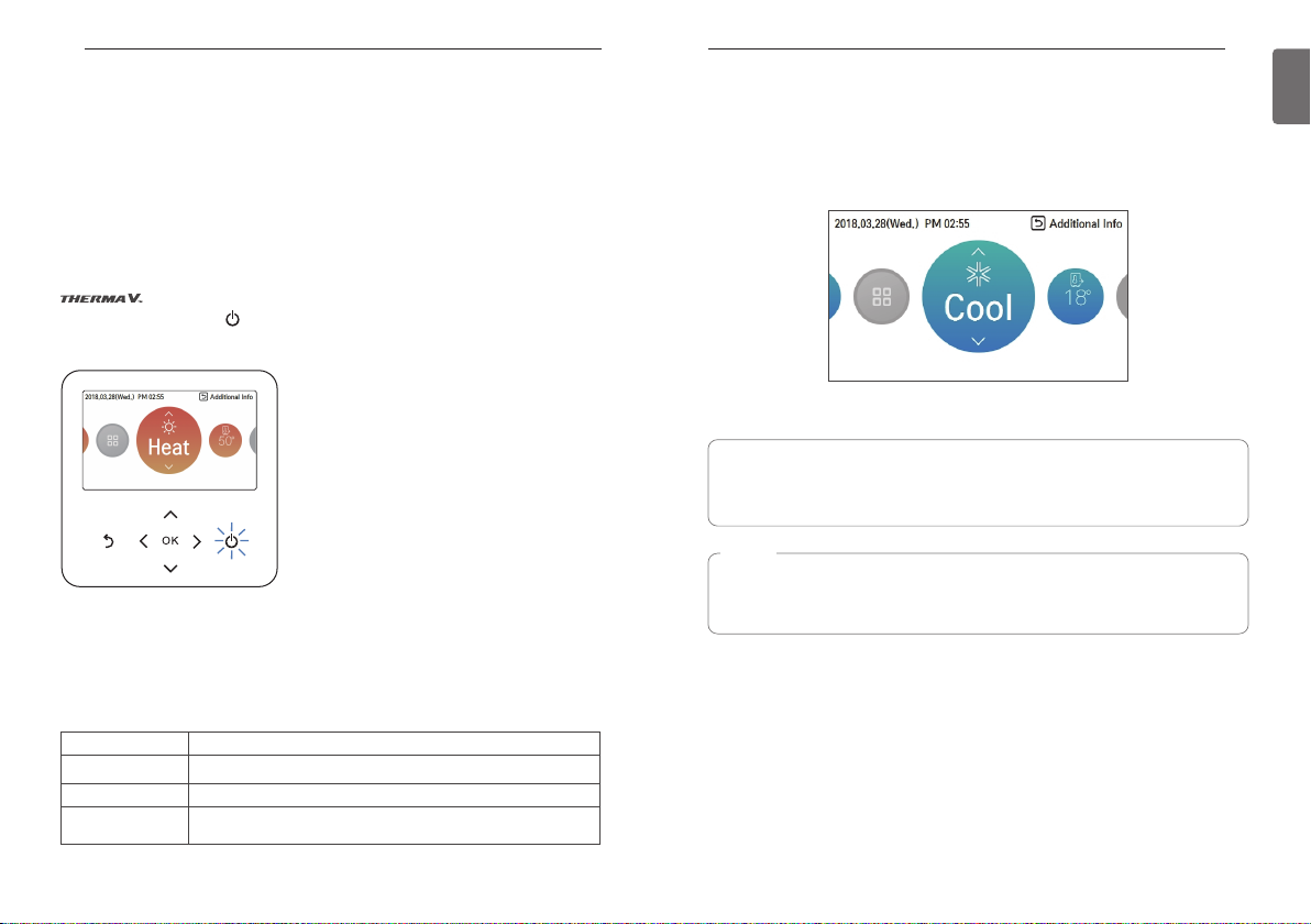
OPERATION SETTING
On / Off
Press the remote controller’s (On/Off) button.
- If the product is in operation, On/Off button will be illuminated.
If the product is in off, On/Off button backlight will be off.
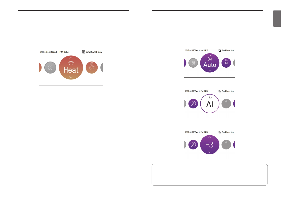
Operation mode
You can easily control the desired operation mode.
In the main screen, press [<,>(left/right)] button to select the operation mode or home leave or
hold category, and press [∧,∨(up/down)] button to set the operation mode.
※Some products may not support some operation modes.
will be turned on or off.
Mode Description
Cool Cool the room to the desired temperature.
Heat Heats the room to the desired room temperature.
AI / Auto
The product automatically provides the appropriate fan speed based on
the temperature of the room.
OPERATION SETTING
Cooling operation
- Set the desired temperature lower than the water temperature.
- water temperature is displayed on the default screen of the remote controller.
- If the setpoint is set higher than the water temperature, then the unit will remain in the cool
mode but will not begin to cool the water temperature exceeds the setpoint.
- If your unit is operating in cooling mode and you press the [On/Off] button the cooling operation
will shut off.
What is 3 minute delay function?
After the cooling stops, when the product is started right away, the reason that the cold
water does not come out is that it is the function to protect the compressor.
The compressor starts after 3 minutes and the cold water comes out.
NOTE
The compressor starts after 3 minutes and the cold water comes out.
The favorable temperature difference between the water inlet temperature and outlet
temperature is 5 °C.
13
ENGLISH
Page 8
OPERATION SETTING
14
Heating operation
- Set the desired temperature higher than the water temperature.
- Water temperature is displayed on the default screen of the remote controller.
- When the desired temperature is set lower than the water temperature, warm water doesn't
come out.
- If your unit is operating in heating mode and you press the [On/Off] button the heatling
operation will shut off.
OPERATION SETTING
AI / Auto operation
This mode is only applied to heating.
In order to save energy and to give highest comfort, setting temperature will follow outside
temperature. If outdoor temperature decreases, heating capacity for the house will increase
automatically in order to keep same room temperature. All parameters will be set by installer
during start-up procedure and will be adapted to the site characteristic.
1. Select AI / Auto mode.
2. Select the desired temperature category
3. Adjust the desired temperature level by press [∧,∨(up/down)] button.
15
ENGLISH
NOTE
Decreasing temperature profile by 3 °C (based on room air temperature)
<Temperature adjust step (unit : °C)>
-5, -4, -3, -2, -1, 0, 1, 2, 3, 4, 5
Cold Hot
Page 9
TEMPERATURE SETTING
16
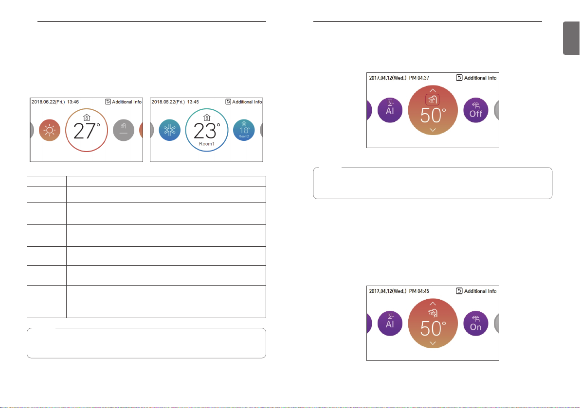
TEMPERATURE SETTING
Controlling desired temperature
You can easily control to the desired temperature.
• In the main screen, press [<, > (left/right)] button to select the desired temperature category,
and press [∧,∨(up/down)] button to set the desired temperature.
- In the cooling, heating, and AI/auto mode, the desired temperature control is possible.
Mode Description
Room
temperature
Room 1 &
Room 2
temperature
Leaving water
temperature
DHW tank
temperature
Water inlet
temperature
Room
temperature +
Leaving water
temperature
Room temperature can be set by using remote sensor's internal temperature
sensor.
Temperature of Room 1 and Room 2 can be set respectively, when 2nd
circuit option is activated in installer mode.
If the desired temperature is lower than the water temperature, the heating
is not performed.
Set the desired temperature higher than the water temperature.
DHW tank temperature setting is available when DHW tank is installed.
This operation is changed to the temperature sensor only, the inlet
temperature sensor, and temperature control logic is the same as the leaving
water temperature operation.
Room temperature can be set by using remote sensor's internal temperature
sensor. If the desired temperature is lower than the water temperature, the
heating is not performed. Set the desired temperature higher than the water
temperature.
TEMPERATURE SETTING
DHW heating operation
Funtion to set whether or not to use a installed DHW tank
Press the [<] or [>] button to focus on the DHW icon, and press the ON / OFF button.
NOTE
• This function is not used when the DHW tank is not installed.
• If you want to know more information, refer function on installation information section.
Quick DHW tank heating
If there is urgent DHW heating demand, Quick DHW Tank Heating mode can be used to reduce
the time to reach target DHW tank temperature by forcibly turning on DHW tank heater.
After reaching target DHW tank temperature or by user’s input to stop, Quick DHW Tank Heating
mode will be finished.
1. Press down [Back] button for a second focused on DHW Heating Operation.
17
ENGLISH
NOTE
The function can be activated according to the installer setting.
Refer to the installer setting “Select temperature sensor”.
Page 10
TEMPERATURE SETTING
18
View temperature
General mode
You can check the current temperature.
• In the main screen, you can enter the monitoring screen by pressing [Back] button.
Mode Description
Room
temperature
temperature
Outlet
temperature
DHW
temperature
Solar heat
temperature
View room temperature
Inlet
View inlet temperature
View outlet temperature
View DHW temperature
(Only displayed when DHW heating mode)
View solar power temperature
(Only displayed when DHW water heating mode)
2ndcircuit mode
Mode Description
Room 1
temperature
Room 2
temperature
temperature
Outlet
temperature
DHW
temperature
Solar heat
temperature
View room 1 temperature
View room 2 temperature
Inlet
View inlet temperature
View outlet temperature
View DHW temperature
(Only displayed when DHW heating mode)
View solar power temperature
(Only displayed when DHW water heating mode)
TEMPERATURE SETTING
19
ENGLISH
Page 11
TEMPERATURE SETTING
20
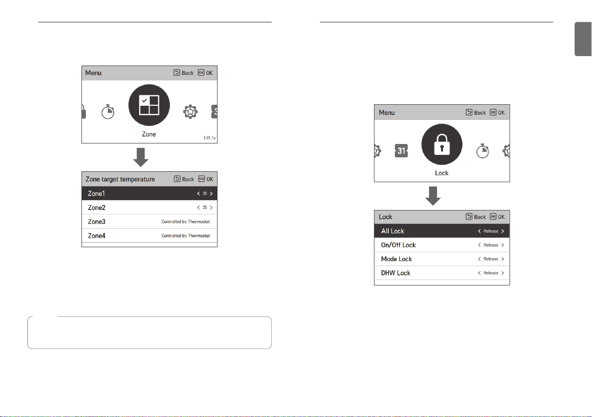
Zone target temperature
It is the function to set the target temperature for valve control by zone.
OK
• The number of zones set in the zone setup menu of installer setting is activated.
- For zone selected by sensor type: Set the target temperature (16 ~ 30 °C) or Open / Close
- For zones selected by thermostat: Display "Controlled by Thermostat"
(Temperature not controllable)
LOCK SETTING
LOCK SETTING
How to enter Lock setting
• In the menu screen, press [<,>(left/right)] button to select “lock setting” category, and press
[OK] button to move to the lock setting list screen.
• In the lock setting list, if you press [∧,∨(up/down)] button, you can turn on/off the
corresponding lock function.
OK
21
ENGLISH
NOTE
This function is not default.
It can be activated, after setting value in installer mode.
Page 12
LOCK SETTING
22
Lock setting – all, on/off, mode, DHW lock
• It is the function to lock the button operation of the remote controller so that children or other
persons cannot use it without permission.
•
It is the function to limit the desired temperature range that can be set in the wired remote controller.
Mode Description
All Lock It locks all button operation of the remote controller.
On/Off Lock It locks the On/Off button operation of the remote controller.
Mode Lock lock It locks the operation mode button operation of the remote controller
DHW Lock lock It locks the DHW On/Off button operation of the remote controller.
NOTE
• DHW lock is not used when the DHW tank is not installed.
• If you want to know more information, refer function on installation information section.
TIMER SETTING
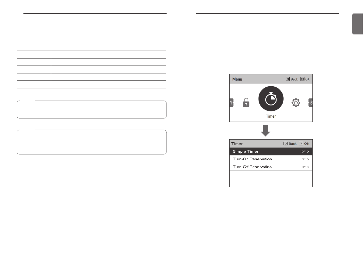
TIMER SETTING
Timer entrance and setting method
• In the menu screen, press [<,>(left/right)] button to select the timer category, and press [OK]
button to move to the timer setting list screen.
• In the timer setting list screen, press [∧,∨(up/down)] button to select the timer to set, and
press [OK] button to move to the detail screen.
• After setting the value, when you press [OK] button, the timer is activated.
• After setting the value, if you press [Back] button, the changed value will not be applied.
23
ENGLISH
NOTE
In the central controller, when the central control temperature range lock is set, the wired
remote controller’s temperature lock setting is cleared.
The temperature change by external equipment is reflected regardless of the remote
controller temperature range lock.
OK
Page 13
TIMER SETTING
24
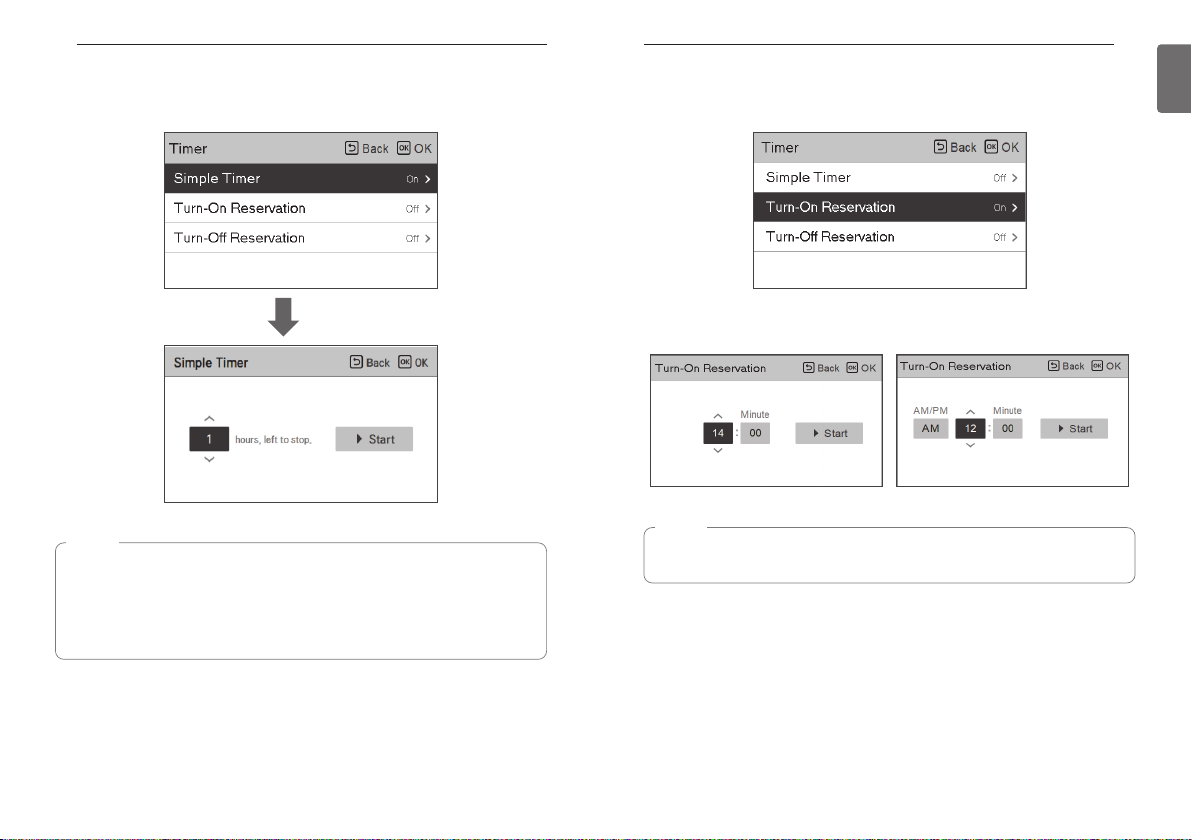
Simple Timer
You can easily set the timer in the range of 1~7 hours in the units of 1 hour.
Turn-On Reservation
The product is automatically turned On at the set timer time.
TIMER SETTING
25
ENGLISH
OK
NOTE
If the product operation is On, the easy timer turns off the operation after the corresponding
time.
If the product operation is Off, the easy timer turns on the operation after the corresponding
time.
If the easy timer operation is turned On/Off before the timer operation, the set timer will be
cleared.
It provides 2 Time formats, 12 Hours(AM/PM) or 24 Hours reference.
NOTE
Even if the Turn-on Reseravation operation is turned On/Off after the setting and before the
timer operation, the set timer is not cleared.
Page 14
TIMER SETTING
26
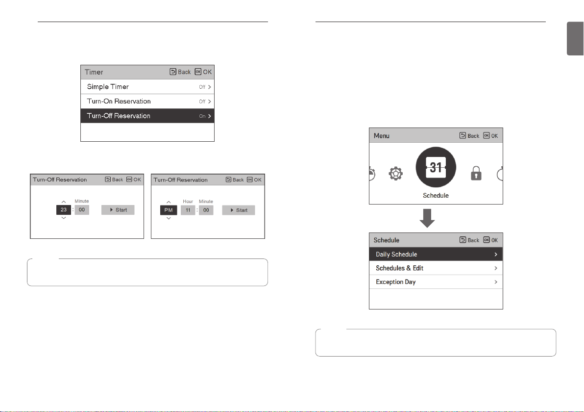
Turn-Off Reservation
The product is automatically turned Off at the set timer time.
It provides 2 Time formats, 12 Hours(AM/PM) or 24 Hours reference.
NOTE
Even if the Turn-off Reservation operation is turned On/Off after the setting and before the
timer operation, the set timer is not cleared.
SCHEDULE SETTING
SCHEDULE SETTING
How to enter schedule
• In the menu screen, press [<,>(left/right)] button so select the schedule category, and press
[OK] button to move to the schedule setting list screen.
• In the schedule setting list screen, press [∧,∨(up/down)] button to select the menu to set, and
press [OK] button to move to the detail screen.
• There are 3 options in schedule formula, depending on product function.
- Room
- Hot water
- Heater of hot water tank
OK
27
ENGLISH
NOTE
Even though there is a heater of hot water tank schedule option, It cannot be activated in
case of sterilization operation.
Page 15
SCHEDULE SETTING
28
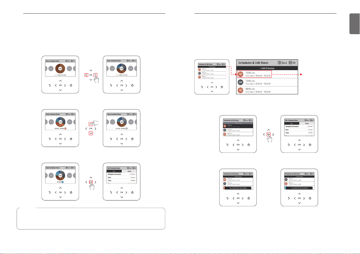
Daily schedule
It is the function that can check the status of the timer (schedule) saved in the remote controller.
• In the schedule list, select the daily schedule status category, and press [OK] button to move to
the detail daily schedule status screen.
• You can use the remote controller’s [<,>(left/right)] button to check the timer information of
other dates.
SCHEDULE SETTING
Schedules & Edit
It is the function that can check the status of the timer (schedule) saved in the remote controller.
• In the schedule list, select the daily schedule status category, and press [OK] button to move to
the daily schedule status detail screen.
• You can use the remote controller’s [<,>(left/right)] button to check other date’s timer
information.
You can check the set
timer’s operation
information (operation
On/Off, operation
mode, desired
temperature), timer
time, period, and day of
week.
29
ENGLISH
• You can use the remote controller’s [∧,∨(up/down)] button to check the corresponding date’s
other timer information.
• Select the timer information, and press [OK] button to move to the corresponding timer’s edit
screen.
NOTE
In the daily schedule status screen, even if the timer (schedule) is set, if the corresponding
date is designated as an exception date, the schedule will not be performed.
Less than 5 schedules per day is recommended.
• You can edit the saved schedule’s timer information.
- Select the schedule to edit using [∧,∨(up/down)] button, and press [OK] button to move to
the edit screen.
• Select the timer information, and press [OK] button to move to the corresponding timer’s edit
screen.
< If schedule is changed > < If schedule is deleted >
Page 16
SCHEDULE SETTING
30
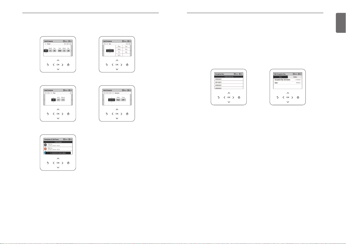
Schedules & Edit – Add schedule
Description of each stage in Add schedule
Stage 1. Period setting Stage 2. Day of week setting
Stage 3. Time setting Stage 4. Operation setting
Add schedule is completed
SCHEDULE SETTING
Exception Day
It is the function to automatically stop the operation on the set timer day.
• In the schedule list, select the exception day category, and press [OK] button to move to the
Exception day designation detail screen.
• In the exception day, you can check, and add/change/delete the exception day information
saved in the remote controller.
- To add an exception day, in the Exception day registration detail screen, designate
year/month/day, and press [OK] button to save the Exception day.
- Select the Exception day to edit using [∧,∨(up/down)] button, and press [OK] button to move
to the edit screen.
- In the exception day edit screen, you can check, delete/change the corresponding exception
day’s setting contents.
- When you change the exception day information, you need to save it after the change.
31
ENGLISH
In ‘Stage 1’, it sets the period to perform the timer.
In ‘Stage 2’, it sets the day of week to perform the timer.
- You can select ‘Everyday / Weekend / Weekdays / Individual selection’.
In ‘Stage 3’, it sets the start time for the timer.
In ‘Stage 4’, it sets the timer operation information.
- If ‘Stop’ is selected, you cannot set the mode / temperature
When stages 1~4 are completed, along with the message of ‘schedule is added’, it moves to
View and edit schedule screen.
Page 17
INFORMATION OF METER INTERFACE
32
FUNCTION SETTING
33
ENGLISH
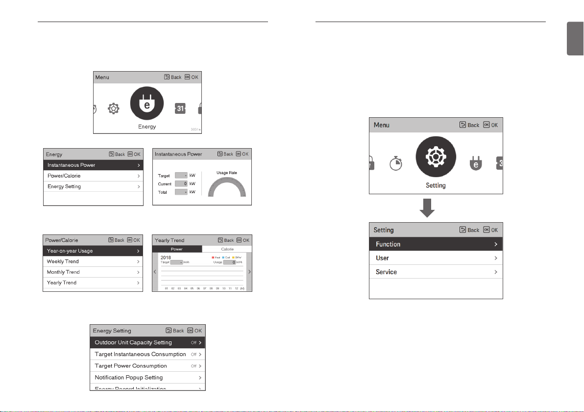
INFORMATION OF METER INTERFACE
It provides useful information on the mount of energy and power during the week/month/year.
Opening “Energy “option, these are presented on screen. You can use this function only when
“Meter interface” is activated in installer setting.
Instantaneous Power
Power/Calorie
The information includes instantaneous power as well as power/calorie usage and up to annual
trend .
Energy Setting
In addition, various energy settings are possible as shown below.
Current value reaches to defined target value, It alerts to you on display
FUNCTION SETTING
How to enter function setting
To enter the menu displayed at the bottom, you need to enter the function setting menu as
follows.
• In the menu screen, press [<,>(left/right)] button to select the setting category, and press [OK]
button to move to the setting list.
• In the setting list, select the function setting category, and press [OK] button to move to the
function setting list.
OK
Page 18
FUNCTION SETTING
34
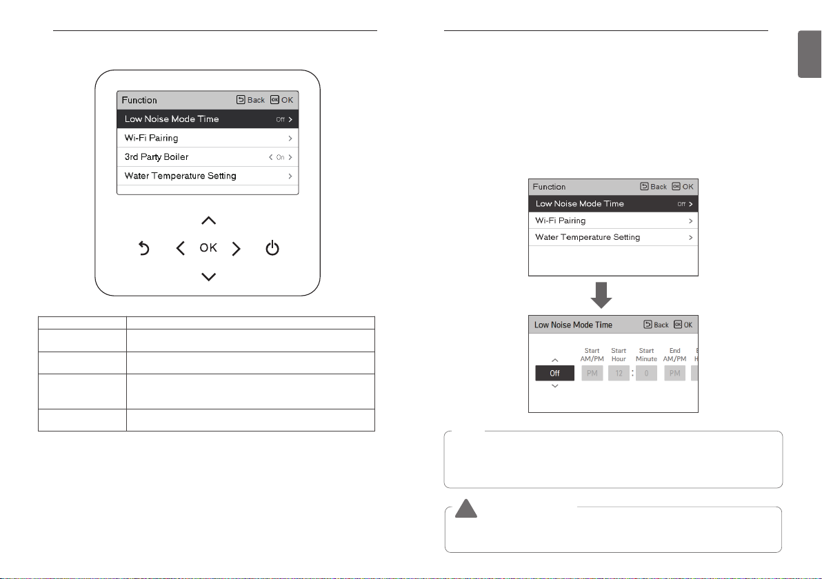
Function setting
FUNCTION SETTING
Low Noise Mode Time
It is the function to set the start and end time of the outdoor unit’s low noise mode operation.
• In the function setting list, select the Low Noise Mode Time category, and press [OK] button to
move to the detail screen.
- After setting the start time and the end time, press [OK] button to move to the upper level
list.
- If the start time and the current time are the same, it enters the outdoor unit low noise
operation mode, and in the monitoring screen, ‘in outdoor unit low noise operation mode’
message is displayed.
- If the end time and the current time are the same, the outdoor unit low noise operation mode
is cleared.
OK
35
ENGLISH
Menu Description
Low Noise Mode Time
Wi-Fi Pairing It is the function to control remotely through network with indoor unit.
Water Temperature
Setting
3ndParty Boiler
It is the function to set the start and end time of the outdoor unit’s
low noise mode operation.
If you select (Air + Water) as the temperature control mode, This
option is activated on screen. It is the function to set target water
temperature.
It is the function to linkage the boiler of other companies. (this
function can be activated, after setting every value in installer mode.)
NOTE
In case that installed with Multi-V, Low noise mode time setting function can be set only
when the installer setting's outdoor unit function M/S setting is set to "Master" and low noise
mode priority function is set to "RMC".
Low noise mode time setting function is only available in some products.
CAUTION
!
If the function is not used, please set it to Off.
When you enter the low noise operation, the cooling capacity may be degraded.
Page 19
FUNCTION SETTING
36
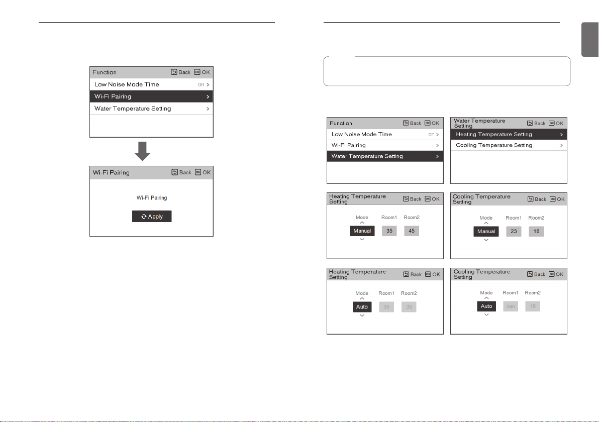
Wi-Fi Pairing
It is the function to control remotely through network with indoor unit.
OK
FUNCTION SETTING
Water Temperature Setting
NOTE
This function is not default.
It can be activated, after setting value in installer mode.
If you choose air+water temperature control way, This option is listed-up on function setting
display. It is the function to set target water temperature.
37
ENGLISH
Page 20
FUNCTION SETTING
38
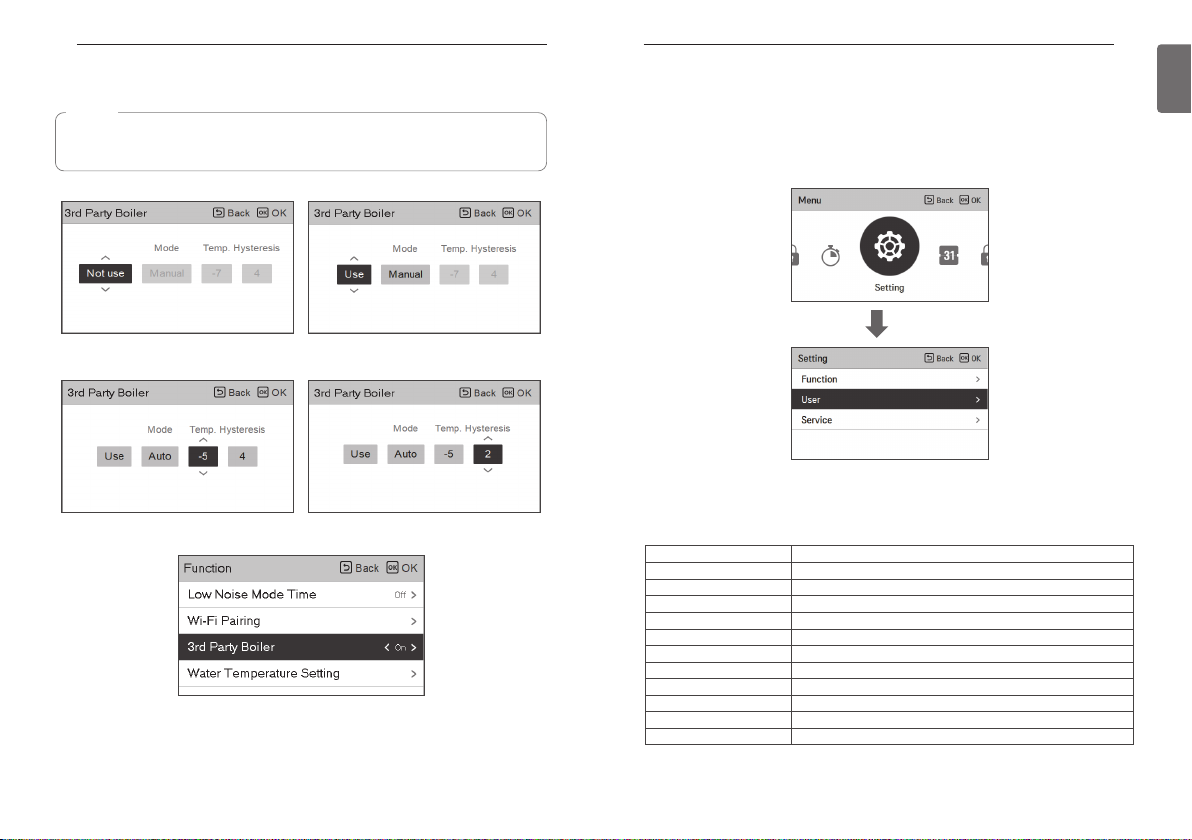
3ndParty Boiler
NOTE
This function is not default.
It can be activated, after setting value in installer mode.
Function to set whether or not to use a installed 3rd Party function.
If the mode of this function is set to “Auto”, you can set temperature of the boiler and
hysteresis, respectively.
Only when the mode is set to "Manual", 3rd party boiler option is activated in function list.
On/off mode of this option are opened by pushing "<" or ">" button simply and easily.
USER SETTING
USER SETTING
How to enter user setting
To enter the menu displayed at the bottom, you need to enter the user setting menu as follows.
• Select the setting category, and press [OK] button to move to the setting list.
• Select the user setting category, and press [OK] button to move to the user setting list.
OK
User Setting
• You can set the product user functions.
• Some functions may not be available in some product types.
Menu Description
Language Set the language to be displayed on the remote controller.
Temperature Unit Set the temperature unit displayed on the remote controller.
Screen Saver Timer Adjust the screen Off time of the remote controller.
LCD Brightness In Idle Adjust the remote controller’s screen brightness.
Date Set the date displayed on the remote controller.
Time Set the time displayed on the remote controller.
Summer Time Set the summer time in the remote controller.
Password
Schedule Initialization Initialize all timer settings in the remote controller.
Theme Set the theme of the remote controller screen.
System Reboot Restart the remote controller.
Set the password to prevent unauthorized change to remote controller settings.
39
ENGLISH
Page 21

USER SETTING
40
Language
Set the language to be displayed on the remote controller.
• In the user setting list, select the language category, and press [OK] button to move to the
detail screen.
• After the setting, if you press [OK] button, the setting is saved and moves to the previous
screen.
OK
USER SETTING
Temperature Unit
Set the temperature unit displayed on the remote controller.
• In the user setting list, select the temperature unit setting category, and press [OK] button to
move to the detail screen.
OK
41
ENGLISH
Language
한국어
Deutsche Español Polski Čeština
ελληνικά Nederlands Românesc Português
Magyar
Українська
English Français Italiano
Hrvatski Srpski Türk
Български Slovenščina
中国
Value
CAUTION
!
The temperature unit function may not work or work differently in some products.
You cannot set the temperature unit in the slave wired remote controller.
Celsius
Fahrenheit
Page 22

USER SETTING
42
Screen Saver Timer
Adjust the screen Off time of the remote controller.
• Select the following setting values using [<,>(left/right)] button.
USER SETTING
Date
Set the date displayed on the remote controller.
• In the user setting list, select the date category, and press [OK] button to move to the detail
screen.
• After the setting, if you press [OK] button, the setting is saved and moves to the previous
screen.
43
ENGLISH
15 seconds 30 seconds (default) 1 min
CAUTION
!
Selecting longer stand by screen will decrease LCD lifespan.
Value
LCD Brightness In Idle
Adjust the remote controller’s screen brightness.
• Select the following setting values using [<,>(left/right)] button.
Value
0 %
CAUTION
!
Selecting brighter stand by screen will decrease LCD lifespan.
10 %
(default)
20 % 30 %
OK
Page 23

USER SETTING
44
Time
Set the time displayed on the remote controller.
• In the user setting list, select the time category, and press [OK] button to move to the detail
screen.
• After the setting, if you press [OK] button, the setting is saved and moves to the previous
screen.
• In the screen, Time display can be presented in the form of AM / PM or 24 hours standard.
USER SETTING
Summer Time
Set the daylight savings time dates in the remote controller.
• In the user setting list, select the summer time setting category, and press [OK] button to
move to the detail screen.
- Summer time: The system to advance the time by 1 hour from the spring when the day is
longer and return back in the fall when the day gets shorter.
- When it becomes AM 02:00 on the DST start date, the current time changes to AM 03:00,
and when it becomes AM 02:00 of the DST end date, the current time changes to AM 01:00.
45
ENGLISH
OK
OK
Page 24

USER SETTING
46
Password
Set the password to prevent unauthorized change to remote controller settings.
• Select the user password setting category, and press [OK] button to move to the detail screen.
- If the password is set, when you enter “menu – setting”, you need to input password to
enter the setting list.
- When you forgot the password, you can initialize the password using the installer setting’s
“password initialization”.
The initialized password is “0000”.
OK
USER SETTING
Schedule Initialization
Initialize all timer settings in the remote controller.
• In the user setting list, select the schedule initialization setting category, and press [OK] button
to move to the detail screen.
- Press the check button to initialize the sleep/simple timer, on/off timer, schedule and
exception date in the remote controller.
OK
47
ENGLISH
Page 25

USER SETTING
48
Theme
Set the theme of the remote controller screen.
• Select either white or black using [<,>(left/right)] button.
System Reboot
Restart the remote controller.
• In the user setting list, select the system restart setting category, and press [OK] button to
move to the detail screen.
- In the detail screen, when you press [OK] button, a popup message is displayed, press the
check button, to restart the system.
- For forced reset, press down [On/Off + Back] button for 5 seconds to restart the system.
SERVICE SETTING
SERVICE SETTING
How to enter service setting
To enter the menu displayed at the bottom, you need to enter the service setting menu as
follows.
• In the menu screen, press [<,>(left/right)] button to select the setting category, and press [OK]
button to move to the setting list.
• In the setting list, select the service setting category, and press [OK] button to move to the
service setting list.
OK
Service setting
• You can set the product service functions.
• Some functions may not be displayed/operated in some product types.
49
ENGLISH
OK
Menu Description
Service contact
Model information View product and capacity information
RMC Version Information Check the remote controller model name and software version.
Open Source License View the remote controller’s open source license.
Check and input the service center phone number that you can call
when there is service issue.
Page 26

SERVICE SETTING
50
Service Contact
Check and input the service center phone number that you can call when there is service issue.
• In the service setting list, select the service contact point and press [OK] button to move to the
detail screen.
• While “edit” button is selected, press [OK] button to move to the edit screen, change it, and
press [OK] button to change the service contact point.
OK
OK
SERVICE SETTING
Model Information
Check product and capacity information to which the remote controller is connected.
• In the service setting list, select model information category, and press [OK] button to move to
the detail screen.
• The unit capacity
- 1 kWh = 1 kBtu * 0.29307
kWh is the result calculated based on Btu, There may be a small difference between
calculated and actual capacity.
Ex) If the unit capacity is 18 kBtu, it is displayed as 5 kWh.
OK
51
ENGLISH
Page 27

SERVICE SETTING
52
RMC Version lnformation
View the remote controller software version.
• In the service setting list, select the RMC version information and press [OK] button to move to
the detail screen
SERVICE SETTING
Open Source License
View the remote controller’s open source license.
• In the service setting list, select the open source license category, and press [OK] button to
move to the detail screen.
53
ENGLISH
OK
OK
Page 28

INSTALLATION
ڹ Top side guide groove ڹ Top side guide groove
ڻRight side
guide
groove
ںLeft side
guide
groove
ڹ Top side guide groove
ںLeft side
guide
groove
ڻRight side
guide groove
ڸRear cable
entry
54
INSTALLATION
Installation of Remote Controller
• After fixing the remote controller installation plate on the desired location, fix it firmly with the
provided screws.
- If the installation plate is not flat on the surface, it may result in the controller being twisted
and cause a defect.
- If there is a mounting box, install the remote controller installation plate using the fixings holes
which suit, as in the below diagrams.
- Do not leave a gap with the wall or product loose after the installation.
• The wired remote controller cable can be installed in 4 directions. Install to the suitable
direction according to the installation environment.
- Installation direction: Rear entry, top side, right side, left side.
- When you install the remote controller cable at the top, right and left side, remove the remote
controller cable guide hole before the installation.
※ Use a long nose pliers to remove the guide hole.
• After removing the hole, trim the cut surface neatly.
INSTALLATION
• After fixing the remote controller top side on the installation plate attached to the wall as in the
following figure, press the bottom side to combine with the installation plate.
- Do not leave a gap in the top, bottom, left, and right side of the remote controller and the
installation plate after combining them.
- Before combining with the installation plate, arrange the cables to avoid interference with the
circuit parts.
<Order of Combining>
Wall Wall
•
When you remove the remote controller from the installation plate, insert a small flat head
screwdriver into the bottom side separation hole and turn clockwise to separate the remote
controller.
- There are 2 separation holes at the bottom part. Slowly separate one by one.
- Be careful not to damage the internal parts during the removal.
<Order of Separation>
Wall Side
• Use the connection cables to connect the indoor unit with the remote controller.
55
ENGLISH
•
When installing the remote control cable on the left side, be sure to install it in the following guide.
1. Make the cable to "ㄱ" shape as shown below.
2. Fit the bent "ㄱ" cable into the upper center piece of case.
3. Tighten the installation plate with preventing interference with the surrounding guide structure.
※ If the cable is assembled in a shape other than "ㄱ", it may not be fastened to the installation
plate due to interference with the structure of case.
Reference. the bent cable shape
The Upper center boss for fixing the bent cable
DC 12 V Red
Signal Yellow
GND Black
OK
Please check if connector is normally connected.
Connecting cable
Indoor
Unit side
• For the following cases, separately purchase and use the cables suitable for the situation.
- Do not install the cable over 50 m. (It may cause communication issues.)
- If the distance between the wired remote controller and the indoor unit is 10 m or more : 10
m extension cable (model name: PZCWRC1)
- If you control several indoor unit products with one wired remote controller : Group control
cable (model name: PZCWRCG3)
NOTE
During the wired remote controller installation, do not bury it in the wall. (It may cause
temperature sensor failure.)
Do not install the cable over 50 m. (It may cause communication defect.)
When you install the extension cable, carefully check the direction of the connectors on the
remote controller side and the product side before the installation.
Specification of extension cable: AWG 24, 3 conductor or above.
Page 29

INSTALLATION
RED(12V)
YELLOW(SIG)
BLACK(GND)
YELLOW(SIG)
BLACK(GND)
YELLOW(SIG)
BLACK(GND)
OK
Indoor unit Main PCB
Indoor unit 1 Indoor unit 2 Indoor unit 3
Master Slave Slave
1
2
No. 1 switch OFF: master (factory ship-out based)
No. 1 switch ON: slave
SlaveSlave
Master
Slave
GND
Signal
12 V
OK
Master
GND
DC 12 V
B Y R B Y R
Signal
GND
DC 12 V
Signal
OK
Master
OK
Slave
56
Group control
1. It is possible to connect 16 indoor units(Max) by one wired remote controller.
※Connect using the group control cable.
① Group control cable (PZCWRCG3): Connect to indoor unit’s wired remote controller connector
② Extension cable (PZCWRC1): Connect to No. ① cable and slave indoor unit’s wired remote
controller connector
While No. ① cable is connected, connect No. ② cable.
NOTE
• Connect only GND and signal cable to the indoor unit set as slave. (If power cable is also
connected, it may cause loss of communication)
• Inquiries related to the purchase of the cable shall be directed to the specialized company
and the service center.
• Change master/slave of the indoor unit.
- For Hydro Kit change the setting with the indoor unit PCB switch.
INSTALLATION
- After completing the master/slave setting in the indoor unit product, turn Off the power of the
indoor unit product, and turn On the power after 1 minute.
NOTE
• During the group control, set only 1 indoor unit as master.
• Indoor unit(Hydro Kit)’s group setting is possible which connected same outdoor unit.
• In case of Group Control, it is possible to use following functions.
- Selection of operation options (operation/stop/mode/set temperature)
- It is not possible at some functions.
• During the individual control, if the master indoor unit DIP switch is set to slave,
malfunction may occur.
2. You can use two wired remote controllers for one indoor unit.
• A dedicated cable must be used for the connection. If necessary, use an extension cable
additionally and install. (2-Remo cable : PZCWRC2, Extension cable : PZCWRC1)
• For normal operation, one should be set as master and the other as slave.
(Refer to the function "Installation setting - RMC master/slave")
• After completing the RMC master/slave setting, turn off the power of indoor unit, and turn
on the power after 1 minutes.
57
ENGLISH
Page 30

INSTALLATION
58
• If you set as Master-Master or Slave-slave for both remote controllers, the following pop-up is
displayed once within 10 minutes after power-on.
If you use the 2-remo function, through the master remote controller you can check the
temperature where the remote controller set as slave is installed.
The room temperature icon changes. This means that the value is detected by the slave remote
controller.
INSTALLER SETTING
INSTALLER SETTING
How to enter installer setting
CAUTION
!
The installer setting mode is the mode to set the remote controller’s detail function. If the
installer setting mode is incorrectly set, it may cause product failure, user’s injury, or property
damage. It must be set by the installation specialist with the installation license, and if it is
installed or changed without installation license, all problems caused will be the responsibility of
the installer, and may void the LG warrenty.
• In the menu screen, press [<,>(left/right)] button to select the setting category, and press
[∧(up)] button for 3 seconds to enter the password input screen for the installer setting.
• Input the password and press [OK] button to move to the installer setting list.
OK OK
※Installer setting password
Main screen → menu → setting → service → RMC version information → SW Version
Example) SW version : 1.00.1 a
In the above case, the password is 1001.
59
ENGLISH
NOTE
Some categories of the installer setting menu may not be available depending on the
product function or the menu name may be different.
Page 31

INSTALLER SETTING
60
Installer setting
• You can set the product user functions.
• Some functions may not be displayed/operated in some product types.
Function Description
Test Run Test run operates Multi V in Cooling mode for max 18 minutes.
3 Minutes Delay Factory use only
Select Temperature Sensor
Dry Contact Mode setting
Central Control address
Override Master/Slave
Pump Test run Water pump test run
Air cooling set temp. setting Adjusting range of 'Setting Air Temperature' in cooling mode
Water cooling set temp.
setting
Air heating set temp. setting Adjusting range of 'Setting Air Temperature' in heating mode
Water heating set temp.
setting
DHW Set Temp.setting Setting DHW set temperature
Cooling / Heating only mode Setting the operation mode lock function.
Screed drying setting Setting for using Step 1 or 2 capacity of electric
Heater on temperature
Water supply off temp. during
cooling setting
Outdoor temp. for auto mode Setting outdoor Min/Max temperature for auto mode.
Indoor air temp. for auto
mode
LWT for auto mode Setting heating flow Min/Max temperature for auto mode
Selection for setting temperature as air temperature or leaving water
temperature or air+leaving water temperature
Dry contact function is the function that can be used only when the
dry contact devices is separately purchased and installed.
When connecting the central control, set the central control address
of the unit.
Override master/slave selection function is to prevent the unit’s
different mode operation. If the unit is set as the slave, it is blocked to
a change of opposite operating mode(cooling/heating).
Adjusting range of 'Setting Leaving Water Temperature' in cooling
mode
Adjusting range of 'Setting Heating Flow Temperature' in heating
mode
Setting outdoor air temperature where half capacity of electric heater
starts operation.
Determine leaving water temperature when the unit is turned off.
This function is used for preventing condensation on the floor in
cooling mode
Setting indoor Min/Max temperature for auto mode
INSTALLER SETTING
Function Description
Tank disinfection setting 1 Setting start/maintain time for pasteurisation
Tank disinfection setting 2 Setting pasteurisation temperature
Tank setting 1 Setting start temperature for operation
Tank setting 2 Setting maintain temperature for operation
Heater priority Determine electric heater and water heater on and off
DHW time setting
Use Heating Tank Heater
Pump frequency setting
(LPM)
TH on/off Variable, heating air
setting
TH on/off Variable, heating
Water setting
TH on/off Variable, cooling air
setting
TH on/off Variable, cooling
Water setting
Heating temp. setting
Cooling temp. setting
Pump setting in heating Set water pump on / off delay option in heating mode
Pump setting in cooling Set water pump on / off delay option in cooling mode
Forced operation
CN_CC setting
Pump Capacity Function to change Water Pump Capacity
Pump frequency setting(RPM) Function to change Water Pump RPM
Smart Grid(SG) setting
Seasonal auto temp setting Set the operating temperature in Seasonal Auto mode
Determine follow time duration : operation time of domestic hot water
tank heating, stop time of domestic hot water tank heating, and delay
time of DHW tank heater operating
It is the function to change the setting value of heating tank heater
operation such as use / non-use and heater delay time of heating tank
heater.
Setting for water flow rate in water piping.
Heating air temperature TH On / Off Type setting
Heating Water Outlet Temperature TH On / Off Type
Cooling air temperature TH On / Off Type setting
Cooling Water Outlet Temperature TH On / Off Type
At the leaving water control in heating mode, the control reference
water temperature position setting
At the leaving water control in cooling mode, the control reference
water temperature position setting
Water pump off After 20 consecutive hours, disable / enable the logic
that drives the water pump by itself
It is the function to set whether to install (use) Dry Contact. (It is not a
function for Dry Contact installation, but it is a function to set the
usage of the unit’s CN_CC port.)
Select whether to use or not use the SG Mode function of the
product, set the operation option value in SG1 step.
61
ENGLISH
Page 32

INSTALLER SETTING
62
Function Description
Modbus Address
Refrigerant Leak Sensor
IDU Address Verification
CN_EXT
ODU Function Master Setting of outdoor function Setting function of Master / Slave.
Low Noise Mode Priority Function to set low noise mode control subject.
Anti-freezing Temperature This function prevents the product from freezing.
Add Zone Install additional valve in product to control additional operation area
Use External Pump Set up to control an external water pump
3rd Party Boiler Configuration to control 3rd party boiler
Meter Interface
Pump Prerun/Overrun
Estimated energy display
Zone Setting
Current flow rate Function to check the current flow rate.
RMC master/slave
Data logging setting Display error history of connected unit
Password Initialization setting
It is function to set the address of the Modbus device that is
externally linked to the product. Modbus address setting function is
available from indoor unit.
The installation of the flare coupling part and the welding part leakage
sensor of the indoor unit is set.
Check the result of Auto Addressing of outdoor unit with remote
control.
Function to set external input and output control according to DI / DO
set by customer using dry contact port of indoor unit. Determine the
use of the contact port (CN_EXT) mounted on the indoor unit PCB
When installing the meter interface to measure energy / calorie in the
product, set unit spec for each port
Set to reach the optimum flow rate by circulating the heating water
with the water pump before heat exchange. After the operation stop,
additional water pump is activated to circulate the heating water.
This function can set to display energy data which outdoor unit
estimated power consumption data without wattmeterd.
When using the zone module, it is the function to set the environment
necessary for control such as the number of use and address setting.
This function is to set master / slvae to use two remote controllers in
one indoor unit.
It is the function to initialize (0000) the password when you forgot the
password set in the remote controller.
INSTALLER SETTING
Test Run
Test run should be performed when charging the additional refrigerant is required. The unit must
be operated in Cooling mode when the refrigerant is being charged. Test run instantly makes the
unit operate in Cooling mode for 18 minutes.
NOTE
If you press any kind of button during this mode, Test Run mode will be finished.
• After the unit operates under Test run mode for 18 minutes, it will be turned off
automatically
OK
63
ENGLISH
Page 33

INSTALLER SETTING
64
3 Minutes Delay
Temporarily eliminates the 3-minute delay function of the outdoor unit Comp
- Factory use only
• In the installer setting list, select 3 Minutes Delay category, and press [OK] button to move to
the detail screen.
INSTALLER SETTING
Select Temperature Sensor
The product can be operated according to air temperature or leaving water temperature. The
selection for setting temperature as air temperature or leaving water temperature is determined.
• In the installer setting list, Select Temperature Sensor category, and press [OK] button to move
to the detail screen.
65
ENGLISH
OK
OK
Value
Water Air Air+Water
Page 34

INSTALLER SETTING
66
Dry Contact Mode
Dry contact function is the function that can be used only when the dry contact devices is
separately purchased and installed.
• Change setting values using [<,>(left/right)] button.
INSTALLER SETTING
Central Control Address
When connecting the central control, set the central control address of the unit.
• In the installer setting list, select Central Control Address category, and press [OK] button to
move to the detail screen.
67
ENGLISH
Value
Auto
manual
NOTE
For dry contact mode related detail functions, refer to the individual dry contact manual.
What is dry contact?
It means the contact point signal input when the hotel card key, human body detection
sensor, etc. are interfacing with the air conditioner.
Added system functionality by using external inputs (dry contacts and wet contacts).
OK
NOTE
Enter address code as hexadecimal value
Front: Central Control Gr. No.
Back side: Central control indoor the number
NOTE
This function is not available for monobloc
Page 35

INSTALLER SETTING
68
Override Master/Slave
Override master/slave selection function is to prevent the unit’s different mode operation. If the
unit is set as the slave, it is blocked to a change of opposite operating mode(cooling/heating).
• Change setting values using [<,>(left/right)] button.
INSTALLER SETTING
Pump test run
The pump test run is the function to test run by operating the water pump. This function can be
used for air vents / flow sensors and others.
• In the installer setting list, Pump Test run category, and press [OK] button to move to the detail
screen.
69
ENGLISH
M/S Description
Master Using group control, this master sets the mode of slave IDU’s.
Slave
If the unit is set as the slave, it blocks a change of opposite operating
mode(cooling/heating)
NOTE
Override M/S setting function is only available in some products.
OK
Page 36

INSTALLER SETTING
70
Air cooling set temp
Determine cooling setting temperature range when air temperature is selected as setting
temperature.
• In the installer setting list, select Air cooling set temp category, and press [OK] button to move
to the detail screen.
INSTALLER SETTING
Water cooling set temp
Determine cooling setting temperature range when leaving water temperature is selected as
setting temperature.
• In the installer setting list, select water cooling set temp category, and press [OK] button to
move to the detail screen.
71
ENGLISH
OK
NOTE
The setting range differs depending on the connected product.
OK
NOTE
Water condensation on the radiator
• While cooling operation, cold water may not flow to the radiator. If cold water enters to
the radiator, dew generation on the surface of the radiator can be occurred.
• The setting range differs depending on the connected product.
Page 37

INSTALLER SETTING
72
Air heating set temp
Determine heating setting temperature range when air temperature is selected as setting
temperature
• In the installer setting list, select Air heating set temp. category, and press [OK] button to move
to the detail screen.
INSTALLER SETTING
Water heating set temp
Determine heating setting temperature range when leaving water temperature is selected as
setting temperature
• In the installer setting list, select Water heating set temp. category, and press [OK] button to
move to the detail screen.
73
ENGLISH
OK
NOTE
The setting range differs depending on the connected product.
OK
NOTE
The setting range differs depending on the connected product.
Page 38

INSTALLER SETTING
74
DHW set temp
Determine heating setting temperature range when DHW temperature is selected as setting
temperature
• In the installer setting list, select DHW set temp. category, and press [OK] button to move to
the detail screen.
INSTALLER SETTING
Cooling / Heating only mode
Set the Operation mode lock when Multi V Indoor unit is used only cooling mode in summer and
Hydro Kit is used only heating in winter.
75
ENGLISH
OK
NOTE
The setting range differs depending on the connected product.
OK
Value1 Value2 (Oil Recovery)
Release -
Set
Type 0
Type 1
Page 39

INSTALLER SETTING
76
Screed drying
This function is a unique feature of AWHP that, when AWHP is installed in a new concrete
structure, controls the specific temperature floor heating out temperature for a certain period of
time to cure the floor cement.
• In the installer setting list, select Screed drying category, and press [OK] button to move to the
detail screen.
OK
How to display
Main Screen - Displays 'Screed drying' on the desired temperature display. The step in progress
at the bottom of the display is displayed.
Setting value
- Start-up step: 1~11
- Maximum temperature : 35 °C~55 °C
- Step 8 Holding time : 1 days~30 days
Function operation
- It is performed by the following procedure from the selected starting step.
- After all steps are completed, turn off the cement curing operation.
Step 1 2 3 4 5 6 7 8 9 10 11
Leaving Water
target
temperature[°C]
Duration
[hours]
25 Max.T Off 25 35 45 Max.T Max.T 45 35 25
72 96 72 24 24 24 24
Holding
time
72 72 72
INSTALLER SETTING
NOTE
• During Screed drying operation, button input except for installer function and temperature
display is restricted.
• When the power is applied again after a power outage during product operation, the
product operation state before power failure is remembered and the product is
automatically operated.
• Screed drying operation stops when an error occurs / When error is cleared, restart
cement Screed drying. (However, if the wired remote control is reset to the error
occurrence state, it is compensated in the unit of one day)
• Upon releasing after an error, Screed drying operation may take up to 1 minute of waiting
time after boot up. (The Screed drying operation status is judged as 1 minute cycle.)
• During Screed drying operation, installer function Screed drying operation is selectable.
• During Screed drying operation, starting operation, low noise mode off, low noise time
setting off, hot water off, solar heat off.
• During Screed drying operation, simple, sleep, on, off, weekly, holiday, heater does not
execute reservation operation.
Holding time
Leaving Water target temperature °C
Pre heating
Heating ready for tiling
Step
77
ENGLISH
※ If the upper limit setting value of the heating LW temperature is 55 °C or lower, it is set to
55 °C forcibly.
If the lower limit setting value of the heating LW temperature is 25 °C or higher, it is set to
25 °C forcibly.
Page 40

INSTALLER SETTING
78
Heater on temperature
Depending on local climatic conditions, it is necessary to change the temperature condition in
which electric heater turns on / off.
• In the installer setting list, Heater on temperature category, and press [OK] button to move to
the detail screen.
OK
NOTE
The setting range differs depending on the connected product.
INSTALLER SETTING
NOTE
• Heater on temperature
Using Half capacity of electric heater : when DIP Switch No. 6 and 7 is set as ‘OFF-ON’ :
- Example : If Heater on temperature is set as ‘-1’ and DIP switch No 6. and 7 is set as
‘OFF-ON’, then half capacity of electric heater will start operation when outdoor
air temperature is below -1 °C and current leaving water temperature or room
air temperature is much belower than target leaving water temperature or
target room air temperature.
Using Full capacity of electric heater : when DIP Switch No. 6 and 7 is set as ‘OFF-OFF’ :
- Example : If Heater on temperature is set as '-1' and DIP switch No 6. and 7 is set as
'OFF-OFF', then full capacity of electric heater will start operation when outdoor
air temperature is below -1 °C and current leaving water temperature or room
air temperature is much belower than target leaving water temperature or
target room air temperature.
79
ENGLISH
Page 41
INSTALLER SETTING
80
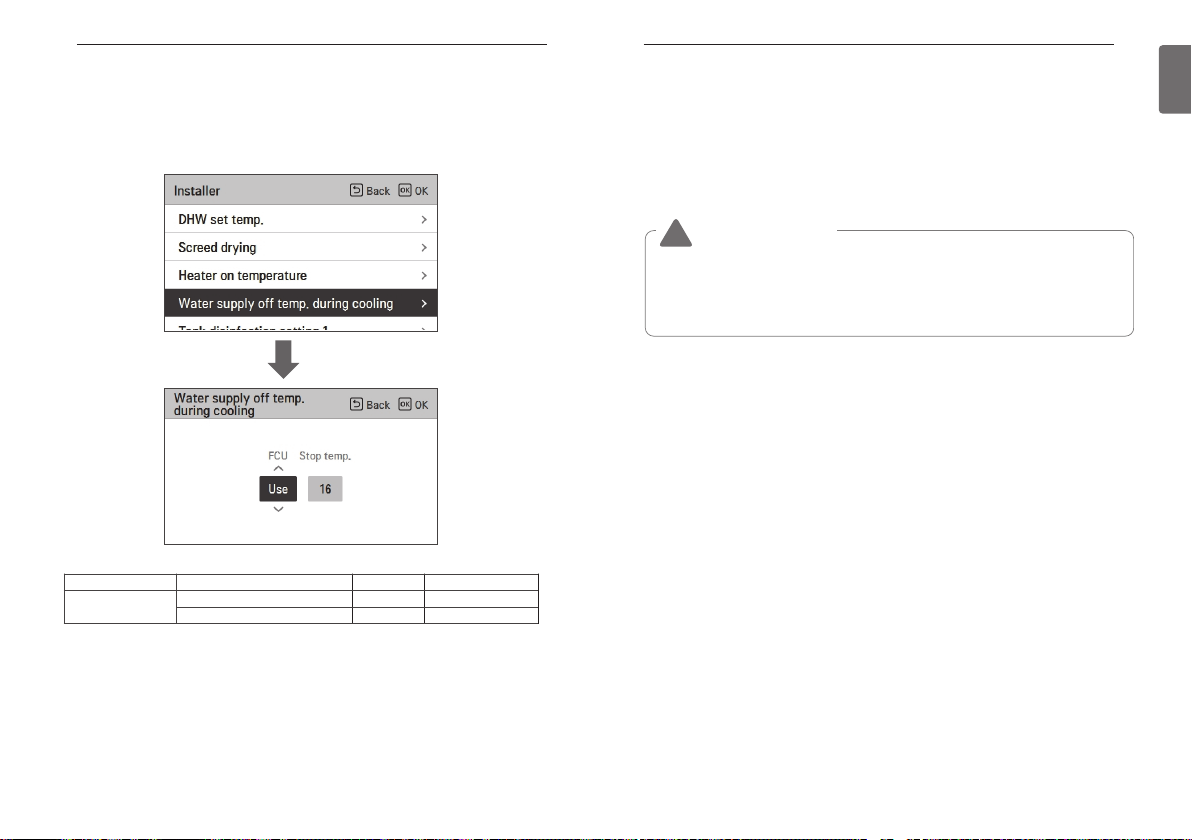
Water supply off temp. during cooling
Determine leaving water temperature when the unit is turned off. This function is used for
preventing condensation on the floor in cooling mode
• In the installer setting list, select Water supply off temp. during cooling category, and press
[OK] button to move to the detail screen.
OK
INSTALLER SETTING
- Stop temp. : cut-off temperature. Stop temp. is valid when FCU is installed.
- FCU : determines if FCU is installed or not.
- Example : If Stop temp. is set as ‘10’ and FCU is ’Use’ and actually FCU is NOT installed in the
water loop, the unit stop operation in cooling mode when the leaving water
temperature is below 10 °C.
- Example : If Stop temp. is set as ‘10’ and FCU is ’Not use’ and actually FCU is installed in the
water loop, the Stop temp. is not used and the unit do NOT stop operation in cooling
mode when the leaving water temperature is below 10 °C.
CAUTION
!
FCU Installation
• If FCU is used, related 2way valve should be installed and connected to the unit PCB.
• If FCU is set as ‘Not use’ but FCU or 2way valve is NOT installed, the unit can do abnormal
operation.
81
ENGLISH
Function Value Default Setting Rang
cooling water
temperature
Water supply off temperature 16 25~16
FCU Use / not use use Use / Not Use
Page 42

INSTALLER SETTING
82
Outdoor temp. for auto mode
It is the function to set outdoor Min/Max temperature for auto mode.
Indoor air temp. for auto mode
It is the function to set indoor Min/Max temperature for auto mode.
INSTALLER SETTING
83
ENGLISH
OK
NOTE
The setting range differs depending on the connected product.
OK
NOTE
The setting range differs depending on the connected product.
Page 43

INSTALLER SETTING
Time
Start time
Max temp
Duration time
Water temperature
(Inside DHW)
Temperature profile
of Disinfection operation
84
LWT for auto mode
It is a function to set the heating flow Min/Max temperature for auto mode.
OK
NOTE
The setting range differs depending on the connected product.
INSTALLER SETTING
Tank disinfection setting 1, 2
• Disinfection operation is special DHW tank operation mode to kill and to prevent growth of
viruses inside the tank.
- Disinfection active : Selecting enable or disable of disinfection operation.
- Start date : Determining the date when the disinfection mode is running.
- Start time : Determining the time when the disinfection mode is running.
- Max temp. : Target temperature of disinfection mode.
- Duration time : Duration of disinfection mode.
OK
OK
85
ENGLISH
NOTE
DHW heating should be enable
• If Disinfection active is set as ’ Not use’, that is ‘disable disinfection mode’, Start date and
Start time is not used.
Page 44

INSTALLER SETTING
86
Tank setting 1
• In the installer setting list, select tank setting 1 category, and press [OK] button to move to the
detail screen.
INSTALLER SETTING
Tank setting 2
• In the installer setting list, select tank setting 2 category, and press [OK] button to move to the
detail screen.
87
ENGLISH
OK
NOTE
The setting range differs depending on the connected product.
OK
Value Range
Hysteresis 4~2
Heating priority Floor heating / DHW
Page 45

INSTALLER SETTING
88
• Tank setting 1, 2
Descriptions for each parameters are as following.
- Min temp. : temperature gap from Max outdoor temp.
- Max outdoor temp. : maximum temperature generated by AWHP compressor cycle.
- Example : If Min temp. is set as ‘5’ and Max outdoor temp. is set as ’48’, then Session A (see
the graph) will be started when the water tank temperature is below 45 °C…. If temperature is
above 48 °C…, then Session B will be started.
- Hysteresis : temperature gap from target DHW temperature. This value is required to frequent
On and Off of water tank heater.
- Heating priority : Determining heating demand priority between DHW tank heating and under
floor heating.
- Example : If user’s target temperature is set as ’70’ and Hysteresis is set as ‘3’, then the
water tank heater will be turned off when the water temperature is above 73 °C. The water
tank heater will be turned on when the water temperature is below 70 °C.
- Example : If Heating priority is set as ‘DHW’, that means heating priority is on DHW heating,
DHW is heated by AWHP compressor cycle and water heater. In this case the under floor can
not be heated while DHW heating. On the other hand, if the Heating priority is set as ‘Floor
heating’, that means heating priority is on under floor heating, DHW tank is ONLY heated by
water heater. In this case the under floor heating is not stopped while DHW is heated.
Water temperature
(Inside DHW water tank)
Water heater off
temperature
Target DHW
temperature (set by user)
Max outdoor temp.
Starting temperature
of DHW heating
Min temp.
Session A
Session A : Heating by AWHP compressor cycle and water heater
Session B : Heating by water heater
Session C : No heating (Water heater is Off)
Session D : Heating by water heater
Session B
Session C
Session D
Hysteresis
Time
INSTALLER SETTING
Heater priority
- Heater priority : determine electric heater and DHW tank heater on and off.
- Example : If Heater priority is set as ‘Main+Boost heater ON’, then electric heater and DHW
tank heater are on and off according to control logic. If Heater priority is set as ‘Boost heater
only ON’, then electric heater is never turned on and only DHW tank heater is on and off
according to control logic.
• In the installer setting list, heater priority category, and press [OK] button to move to the detail
screen.
OK
Value
Boost heater only ON Main+Boost heater ON
89
ENGLISH
NOTE
DHW heating does not operate when it is disabled.
Page 46

INSTALLER SETTING
90
DHW time setting
Determine following time duration : operation time of DHW tank heating, stop time of DHW tank
heating, and delay time of DHW tank heater operating.
- Active time : This time duration defines how long time DHW tank heating can be continued.
- Stop time : This time duration defines how long time DHW tank heating can be stopped. It is
also regarded as time gap between DHW tank heating cycle.
- Boost heater delay time : This time duration defines how long time DHW tank heater will not be
turned on in DHW heating operation.
- Example of timing chart :
1
DHW tank
is enabled
DHW tank
DHW tank
0
1
0
1
0
1
0
AS SS
BB
Time
heating is enabled
DHW tank heater
heating operation
heater operation
1=active / 0=not active
❈
A = Active time
❈
S = Stop time
❈
B = Boost heater delay time
❈
OK
INSTALLER SETTING
Use Heating Tank Heater
It is the function to change the setting value of heating tank heater operation such as use / nonuse and heater delay time of heating tank heater
• Change setting values using [<,>(left/right)] button.
OK
Value1 Value2 Value3
Use/Not Use Priority Delay time
Not use - -
Use disinfect - -
Use
Cycle
Heater / Cycle
10, 20, 30, 40, 50, 60,
90, 120, 1440
91
ENGLISH
Page 47

INSTALLER SETTING
92
Pump frequency setting (LPM)
It is a function to set for water flow rate in water piping.
OK
INSTALLER SETTING
TH on/off Variable, heating air
It is a function to adjust the heating air temperature Thermal On / Off temperature according to
the field environment in preparation for heating or heating claim.
• You can set the following setting values using [<,>(left/right)] button.
93
ENGLISH
Range
15 ~ 92 LPM
Value
Type0 -0.5 °C 1.5 °C
Type1 -1 °C 2 °C
Type2 -2 °C 3 °C
Type3 -3 °C 4 °C
Description
TH On TH Off
Page 48

INSTALLER SETTING
94
TH on/off Variable, heating water
It is a function to adjust the heating water temperature Thermal On / Off temperature according
to the field environment in preparation for heating or heating claim.
• You can set the following setting values using [<,>(left/right)] button.
INSTALLER SETTING
TH on/off Variable, cooling air
It is a function to adjust the cooling air temperature Thermal On / Off temperature according to
the field environment in preparation for cooling or cooling claim.
• You can set the following setting values using [<,>(left/right)] button.
95
ENGLISH
Value
Type0 -2 °C 2 °C
Type1 -3 °C 3 °C
Type2 -4 °C 4 °C
Type3 -1 °C 1 °C
Description
TH On TH Off
Value
Type0 0.5 °C -0.5 °C
Type1 1 °C -1 °C
Type2 2 °C -2 °C
Type3 3 °C -3 °C
Description
TH On TH Off
Page 49

INSTALLER SETTING
96
TH on/off Variable, cooling water
It is a function to adjust the cooling water temperature Thermal On / Off temperature according
to the field environment in preparation for cooling or cooling claim.
• You can set the following setting values using [<,>(left/right)] button.
INSTALLER SETTING
Heating temp. setting
• At the leaving water control in heating mode, the control reference water temperature position
setting
- If the air / leaving water temperature selection setting is set to leaving water temperature
• Change setting values using [<,>(left/right)] button
97
ENGLISH
Value
Type0 0.5 °C -0.5 °C
Type1 1 °C -1 °C
Type2 2 °C -2 °C
Type3 3 °C -3 °C
Description
TH On TH Off
Value
Outlet (Default) Inlet
Page 50

INSTALLER SETTING
98
Cooling temp. setting
• At the leaving water control in cooling mode, the control reference water temperature position
setting
- If the air / leaving water temperature selection setting is set to leaving water temperature
• Change setting values using [<,>(left/right)] button
INSTALLER SETTING
Pump setting in heating
• It is a function to help the water pump's mechanical life by putting the water pump's rest time
• Installer setting function to set water pump operation / delay time option in heating mode
• In the installer setting list, select Pump setting in heating category, and press [OK] button to
move to the detail screen.
99
ENGLISH
Value
Outlet (Default) Inlet
OK
Type Time setting Operation continue
On 1 Minute~60 minutes -
Off 1 Minute~60 minutes -
Page 51

INSTALLER SETTING
100
Pump setting. in cooling
• It is a function to help the water pump's mechanical life by putting the water pump's rest time
• installer setting function to set water pump operation / delay time option in cooling mode
• In the installer setting list, select Pump setting in cooling category, and press [OK] button to
move to the detail screen.
OK
Type Time setting Operation continue
On 1 Minute~60 minutes -
Off 1 Minute~60 minutes -
INSTALLER SETTING
Forced operation
• If the product is not used for a long time, the product will be forced to operate to prevent pump
failure and PHEX freezing
• Water pump off After 20 consecutive hours, disable / enable the logic that drives the water
pump by itself
• In the installer setting list, select Forced operation category, and press [OK] button to move to
the detail screen
OK
Type Use Not use
Oper. Cycle 20 minutes~60 minutes -
Oper. Time 1 Minute~60 minutes -
101
ENGLISH
Page 52

INSTALLER SETTING
102
CN_CC
It is the function to set the usage of the unit’s CN_CC port.
• Change setting values using [<,>(left/right)] button
INSTALLER SETTING
Pump Capacity
It is a function to enable installer to control Pump capacity application model.
• In the installer setting list, select Pump Capacity category, and press [OK] button to move to
the detail screen.
103
ENGLISH
Value Description
D/C Automatic
D/C Not Installed Do not use (install) Dry Contact
D/C Installed Use (install) Dry Contact
When power is applied to the product, the unit when the contact point
is on in Dry Contact installed state recognizes Dry Contact installation
NOTE
CN_CC is the device connected to the unit to recognize and control the external contact
point.
OK
Value Description
100 (Default)
10~100 : %
Change unit: 5
Page 53

INSTALLER SETTING
104
Pump frequency setting (RPM)
It is a function to enable installer to control pump RPM of BLDC pump application model.
• In the installer setting list, select Pump frequency setting(RPM) category, and press [OK] button
to move to the detail screen.
• The function is not available for some products.
INSTALLER SETTING
Smart Grid(SG)
It is the function to enable / disable the SG Ready function and to set the reference value at SG2
step.
• In the installer setting list, select Smart Grid(SG) category, and press [OK] button to move to
the detail screen.
105
ENGLISH
OK
Value Description
3 500
500~3 700 : RPM
Change unit : 10
OK
Value Mode
Not use (Default) -
Step 0
Use
Step 1
Step 2
Page 54

o
INSTALLER SETTING
106
Seasonal auto temp
It is the function to set the operation reference value in Seasonal Auto mode.
• In the installer setting list, select Seasonal auto temp category, and press [OK] button to move
to the detail screen.
OK
Function Description Boundary
Outdoor1,Heat (Out1) Heating lower ambient temp
Outdoor2,Heat (Out2) Heating higher ambient temp
Outdoor3,Cool (Out3) Cooling lower ambient temp
Outdoor4,Cool (Out4) Cooling higher ambient temp
Water1,Heat (LW1)
Water 2,Heat (LW2)
Water3,Cool (LW3)
Water4,Cool (LW4)
Air 1, Heat (RA1)
Air 2, Heat (RA2)
Air 3, Cool (RA3)
Air 4, Cool (RA4)
Heating higher water temp
Heating lower water temp
Cooling higher water temp
Cooling lower water temp
Heating higher air temp
Heating lower air temp
Cooling higher air temp
Cooling lower air temp
Out1 ≤ Out2-1
Out2 ≥ Out1 +1
Out2 ≤ Out3 -5
Out3 ≥ Out2 +5
Out3 ≤ Out4 -1
Out4 ≥ Out3 +1
LW1 ≥ LW2
LW1 ≥ LW2
LW3 ≥ LW4
LW3 ≥ LW4
RA1 ≥ RA2
RA1 ≥ RA2
RA3 ≥ RA4
RA3 ≥ RA4
- Setting range: Celsius
- Seasonal Auto Driving mode: Heating, Heating & Cooling, Air-conditioning
* If heating mode is selected, heating & cooling or cooling can not be selected.
- Depending on the air / outflow control selection value, the water / air related setting value is
displayed on the screen.
Set Point in graph Attribute
Set point 5 Outdoor Air Temp.
Set point 6 Outdoor Air Temp.
Set point 7 Outdoor Air Temp.
Set point 8 Outdoor Air Temp.
Set point 1
Set point 2
Set point 3
Set point 4
Set point 1
Set point 2
Set point 3
Set point 4
Auto Adjustable Target
Temp.
Auto Adjustable Target
Temp.
Auto Adjustable Target
Temp.
Auto Adjustable Target
Temp.
Auto Adjustable Target
Temp.
Auto Adjustable Target
Temp.
Auto Adjustable Target
Temp.
Auto Adjustable Target
Temp.
INSTALLER SETTING
In this mode, setting temperature will follow outdoor temperature automatically. This mode adds
the cooling season function to the conventional weather dependent operation mode.
Auto-Adjustable
Target Temperature
Set point 1
Set point 2
Set point 3
Set point 4
Temperature profile
of weather dependent operation
Set point 5 Set point 6 Set point 7 Set point 8
Heating
Cooling
Outdoor
air temperature
107
ENGLISH
Page 55

INSTALLER SETTING
108
Modbus Address
It is function to set the address of the Modbus device that is externally linked to the product.
Modbus address setting function is available from indoor unit.
• In the installer setting list, select Modbus Address , and press [OK] button to move to the detail
screen.
INSTALLER SETTING
Refrigerant Leak Sensor
The installation of the flare coupling part and the welding part leakage sensor of the indoor unit is
set.
• Change setting values using [<,>(left/right)] button.
109
ENGLISH
OK
NOTE
To use this function, switch No.1 of option switch 1 must be turned ON.
Value
Installed
Not Installed
Page 56
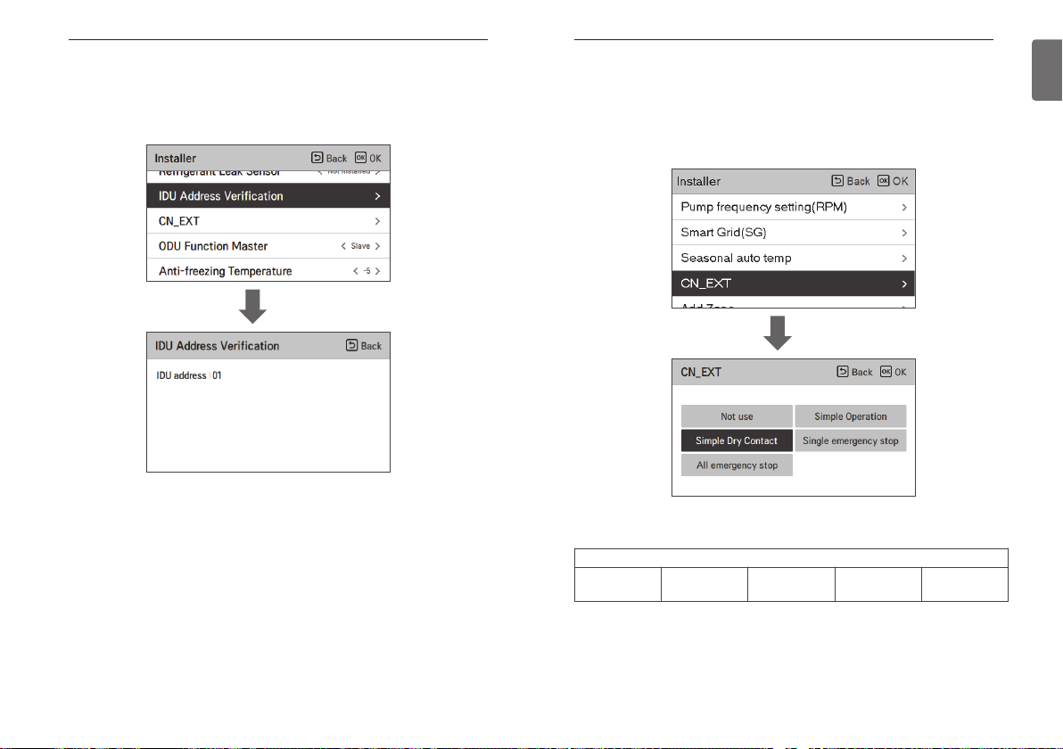
INSTALLER SETTING
110
IDU Address Verification
Check the result of Auto Addressing of outdoor unit with remote control.
• In the installer setting list, select the indoor unit address check category, and press [OK] button
to move to the detail screen.
OK
INSTALLER SETTING
CN_EXT
It is a function to control external input and output according to DI type set by customer using
CN-EXT Port.
• In the installer setting list, select CN-EXT Port category, and press [OK] button to move to the
detail screen.
OK
111
ENGLISH
Not use Simple Operation
Value
Simple Dry
Contact
Single emergency
stop
All emergency
stop
Page 57

INSTALLER SETTING
112
ODU Function Master
It is the function to set the outdoor unit’s function Master / Slave.
• Change setting values using [<,>(left/right)] button.
INSTALLER SETTING
Low Noise Mode Priority
It is the function to set the low noise mode control main agent. (It is the function to set that only
one of the outdoor unit / remote controller can control the low noise operation.)
• Change setting values using [<,>(left/right)] button.
113
ENGLISH
Value Description
Slave
Master
!
※When you change the outdoor unit function master setting from master to slave, check the
operation status of the outdoor unit function (outdoor unit low noise operation, smart load
control) and make sure to stop the outdoor unit function before the change.
No noise operation control subject setting
No noise operation time setting
No defrost mode setting
Low noise operation control subject can be set
Low noise operation time setting
Defrost mode can be set
CAUTION
Value Description
RMC
ODU(default)
Low noise operation switch setting of outdoor unit PCB is ignored.
Function Setting - Low noise operation time menu is activated.
It is controlled by outdoor unit according to switch setting value of low
noise operation of outdoor unit PCB.
Function Setting - Low noise operation time menu is inactivated
Page 58

INSTALLER SETTING
114
Anti-freezing Temperature
Anti-freeze temperature setting is available in installer mode. It prevents frostbite from happening
In the range of -25 to -5 degree celsius.
• Change setting values using [<, >(left/right)] button
NOTE
To use this function, the antifreeze short pin must be open and switch No.2 in Option SW 3
must be on.
INSTALLER SETTING
Add Zone
Function to set whether or not to use a installed 2nd circuit function using mixing kit.
You can set valve closing time[sec] and hysteresis temperature[ °C] on screen by yourself.
115
ENGLISH
ON
OFF
SW3
1 2 3 4
Antifreeze
short Pin
Activating this function, It allows 2 zones(Room1, Room2) temperature to be controlled,
separately.
- In case of heating, the temperature of Room1 can not be set higher than Room2 temperature.
CN_FLOW2
1234
1234
12345678
- In case of cooling, the temperature of Room1 can not be set lower than Room2 temperature.
Setting range
- Add Zone (2nd Circuit function setting) : Use / Not Use
- Value Closing Time : 60~999 seconds (Default: 240)
- Hysteresis (Thermal On / Off ) : 1~5 °C (Default: 2)
Indoor PCB
Page 59

INSTALLER SETTING
116
Use External Pump
This function can be set to control the external water pump.
• In the installer setting list, select Use External Pump category, and press [OK] button to move
to the detail screen.
Value
Not use Use
INSTALLER SETTING
3rdParty Boiler
This function is to configure the 3rd party boiler to be controlled.
If the status of this function is “Use”, you can choose control mode of boiler, Auto or Manual.
If the mode of this function is set to “Auto”, you can set temperature of the boiler and
hysteresis, respectively.
117
ENGLISH
External boiler ON condition :
- If outdoor temperature ≤ external boiler operation temperature value (installer setting), turn off
the indoor unit and operate the external boiler.
External boiler OFF condition :
- If External air temperature ≥ external boiler operation temperature value (installer setting) +
Hysteresis (installer setting), turn off external boiler operation and operate indoor unit
Page 60

INSTALLER SETTING
118
Meter Interface
It is the function that can check the status of energy and power on screen. It collects and
calculates power or calorie data to create data for energy monitoring and energy warning alarm
pop-ups. This function can be activated in installer mode.
INSTALLER SETTING
Estimated energy display
This function can set to display energy data which outdoor unit estimated power consumption
data without wattmeter.
119
ENGLISH
OK
There are 2 options, modbus address and unit, in this function. Activating the modbus address
option, you choose one address(B0 or B1) or don’t use. Then, you set the port and specification
in range of 0000.0~9999.9 [pulse/ kW] as shown in the figure below.
Setting value Description
Use Display energy consumption data which outdoor unit estimated
Not Use Not display energy consumption data which outdoor unit estimated
Page 61

INSTALLER SETTING
120
Pump Prerun/Overrun
Pump Prerun operates to ensure sufficient flow before the compressor is operated. This is a
function that allows heat exchange to work smoothly.
Pump Overrun is a function to prevent water pump failure and to help mechanical life. If the
water pump has been off for 20 hours, Water pump will operate for the set time
OK
NOTE
The setting range differs depending on the connected product.
INSTALLER SETTING
Solar Thermal System
It is function to set operation reference value in Solar Thermal System.
In the installer setting list, select Solar thermal system category, and press [OK] button to move
to the detail screen.
121
ENGLISH
NOTE
To use this function, switch No.2 of option switch 2 must be turned ON and No.3 of option
switch 2 must be turned OFF.
Page 62

INSTALLER SETTING
122
Descriptions for each parameters are as following.
• Solar collector set temp
- Min temp : It is the minimum solar collector temperature at which the solar thermal system
- Max temp : It is the maximum solar collector temperature at which the solar thermal system
• TH on/off Variable, solar
- Temp on : It is the temperature difference between the current solar thermal temerature and
- Temp off : It is the temperature difference between the current solar thermal temerature and
- Example : If the current solar collector temperature is 80 °C and Temp on is set to 8 °C, the
• DHW Set Temp
- Max : It is maximum temperature of DHW that can be reached by solar thermal system.
• Boost Heater
- Enable : DHW tank heater can be used when operating the Solar Thermal system.
- Disable : DHW tank heater cannot be used when operating the Solar Thermal system.
• Solar pump flush schedule
- It is the function to circulate the solar water pump intermittently for solar collector
• Solar Pump flush setting
- Oper.Cycle : When using the solar pump flush function, the solar water pump operates at the
- Oper.Time : When using the solar pump flush function, the solar water pump operates during
can operate.
can operate
DHW tank temperature at which the solar thermal system operates.
DHW tank temperature at which the solar thermal system stops.
solar thermal system operates when the DHW tank temperature is less than 72 °C.
In the same case, if Temp off is set to 2 °C, Solar Thermal System stops when
DHW temperature is 78 °C.
temperature detection when the solar water pump does not operate for a long time. Turn on
to use this function.
set time.
the set time.
INSTALLER SETTING
123
Zone
It is the function to set the environment and check the operating status when using the zone
module.
In the installer setting list, select the zone category, and press [OK] button to move to the detail
screen.
<Zone setting>
When using the zone module, it is the function to set the environment necessary for control such
as the number of use and address setting.
ENGLISH
Function Value Range Default
Solar collector set temp
DHW set temp Max 20 °C~90 °C 80 °C
TH on/off Variable, solar
Boost Heater Boost Heater Enable/Disable Enable
Solar pump flush schedule
Solar pump test run Pump test Run Start/Stop Stop
Solar pump flush setting
Min 5 °C~50 °C 10 °C
Max 60 °C~105 °C 95 °C
Temp On 3 °C~40 °C 8 °C
Temp Off 1 °C~20 °C 2 °C
On/OFF On/Off On
Start Hour, Start Minute 00:00~24:00 6:00
End Hour, End Minute 00:00~24:00 18:00
Oper.Cycle 30 min~120 min 60 min
Oper.Time 1 min~10 min 1 min
Function Value Range
Step1 Number of Zones
Step2 Address
Step3 Control device selection
Step4 TH on/off variable
Number of Modules Not use, 1 ~ 4
Number of Zones Up to two zones can be used for one module.
Address for each
module
Type selection
for zone
Heat Type0 ~ Type3
Cool Type0 ~ Type3
C0 ~ C3
*It can be set as many as the number of
modules
Sensor / Thermostat
NOTE
Th on/off variable can be set only when the control device selection is set to "Sensor" on the
step 3.
Page 63

INSTALLER SETTING
124
<Valve test>
This function is provided to check if each valve works properly after installing / setting the zone
module.
Value1 Value2 Description
Start / Stop Open / Close When selecting zone, the status is “OPEN”
NOTE
If the test is not stopped after the start of valve test, the test is automatically terminated
after 60 minutes.
INSTALLER SETTING
Current flow rate
It is the function to check the current flow rate.
• In the installer setting list, select Current Flow Rate category, and press [OK] button to move to
the detail screen. The current flow rate can be checked. (Range : 7 ~ 80 L/min)
• The function is not available for some products.
OK
125
ENGLISH
Page 64

INSTALLER SETTING
126
Data logging
It is the function to set the operation reference value in Seasonal Auto mode.
• In the installer setting list, select Data logging category, and press [OK] button to move to the
detail screen.
OK
NOTE
Error history lookup range: 50
Error history information
Item: date, time, mode (including Off), set temperature, incoming temperature, outgoing
temperature, room temperature, Hot water operation / stop, Hot water set
temperature, Hot water temperature, Outdoor unit On / Off, Error code
Number of Display: Within 50
- Save criteria ν
ν Error occurred, released
ON / OFF of outdoor unit operation
INSTALLER SETTING
Password Initialization
It is the function to initialize (0000) when you forgot the password set in the remote controller.
• In the installer setting list, select the password initialization setting category, and press [OK]
button to move to the detail screen.
• When you press “initialization” button, a popup screen appears, and when you press “check”
button, password initialization starts, and the user password is changed to 0000.
OK
127
ENGLISH
Page 65

INSTALLER SETTING
128
RMC master/slave
This function is to set master / slave to use two remote controllers in one indoor unit.
NOTE
After completing the RMC master/slave setting, turn off the power of indoor unit, and turn
on the power after 1 minutes.
NOTICE
NOTICE
OPEN SOURCE SOFTWARE NOTICE INFORMATION
To obtain the source code under GPL, LGPL, MPL, and other open source licenses, that is
contained in this product, please visit http://opensource.lge.com
all referred license terms, warranty disclaimers and copyright notices are available for download.
LG Electronics will also provide open source code to you on CD-ROM for a charge covering the
cost of performing such distribution (such as the cost of media, shipping, and handling) upon
email request to opensource@lge.com
shipment of this product. This offer is valid to anyone in receipt of this information.
. This offer is valid for a period of three years after our last
. In addition to the source code,
129
ENGLISH
Page 66

 Loading...