


OWNER'S &
INSTALLATION MANUAL
AIR
CONDITIONER
Please read this installation manual completely before installing the product.
Installation work must be performed in accordance with the national wiring standards by authorized personnel only.
Please retain this installation manual for future reference after reading it thoroughly.
NEW WIDE WIRED
REMOTE CONTROLLER
ENGLISH
PREMTB001 / PREMTBB01
MFL69525701
Rev.03_082217
Copyright © 2015 - 2017 LG Electronics Inc. All Rights Reserved.
www.lg.com

TIPS FOR SAVING ENERGY
2
ENGLISH
IMPORTANT SAFETY INSTRUCTIONS
3
ENGLISH
TIPS FOR SAVING ENERGY
Here are some tips that will help you minimize the power consumption when you use the air
conditioner. You can use your air conditioner more efficiently by referring to the instructions
below:
• Do not cool excessively indoors. This may be harmful for your health and may consume more
electricity.
• Block sunlight with blinds or curtains while you are operating the air conditioner.
• Keep doors or windows closed tightly while you are operating the air conditioner.
• Adjust the direction of the air flow vertically or horizontally to circulate indoor air.
• Speed up the fan to cool or warm indoor air quickly, in a short period of time.
• Open windows regularly for ventilation as the indoor air quality may deteriorate if the air conditioner is used for many hours.
• Clean the air filter once every 2 weeks. Dust and impurities collected in the air filter may block the
air flow or weaken the cooling / dehumidifying functions.
For your records
Staple your receipt to this page in case you need it to prove the date of purchase or for warranty
purposes. Write the model number and the serial number here:
Model number :
Serial number :
You can find them on a label on the side of each unit.
Dealer’s name :
Date of purchase :
IMPORTANT SAFETY INSTRUCTIONS
READ ALL INSTRUCTIONS BEFORE USING THE APPLIANCE.
Always comply with the following precautions to avoid dangerous situations and ensure peak
performance of your product
• The installation requires expert skills, and it should be installed by the service center or other
shops specialized in the installation and recognized by our company.
• For all the problems arising after installation by someone who has no relevant qualifications, our
company will not provide free service.
• The following safety cautions are provided to prevent unexpected dangers or losses.
WARNING
!
If the user does not follow the mandatory items, it may result in serious injury or death.
CAUTION
!
If the user does not follow the mandatory items, it may cause personal injury or property damage.
Warning and Caution are to call the user’s attention to the possible danger. Read the fol-
!
low them carefully in order to prevent a safety accident.
Warning and Caution are indicated in this guide and the product itself to help protect the
users from danger.
WARNING
!
Installation
• Ensure that all installation, service or re-installation is carried out by a qualified person.
Do not dismantle or modify the product in any way. Failure to follow these instructions may result in
a fire, explosion or electric shock
In-use
• Do not place flammable material or stuffs around the controller.
- It will cause fire.
• Do not allow water to run into the product.
- It will cause electric shock or breakdown.
• Do not give the shock to the product.
- It will cause breakdown when giving the shock to the product.
• Request to the service center or installation specialty store when the product becomes wet.
- It will cause fire or electric shock.
• Do not expose to shock using sharp and pointed objects.
- It will cause breakdown by damaging parts.
CAUTION
!
In-use
• Do not clean using the powerful detergent like solvent but use soft cloths.
- It will cause fire or product deformation.
• Do not press the screen using powerful pressure or select two buttons.
- It will cause product breakdown or malfunction.
• Do not touch or pull the lead wire with wet hands.
- It will cause product breakdown or electric shock.

TABLE OF CONTENTS
4
ENGLISH
TABLE OF CONTENTS
3 IMPORTANT SAFETY
INSTRUCTIONS
6 PART DESCRIPTION
7 OWNER’S INSTRUCTION
7 Standard Operation – Standard
Cooling
8 Standard Operation – Power Cooling
9 Standard Operation – Heating Mode
10 Standard Operation – Dehumidifying
Mode
11 Standard Operation – Monsoon
Dehumidifying Mode
12 Standard Operation – Fan Mode
13 Standard Operation – Auto Operation
Mode
14 Standard Operation – Temperature
Setting / Room Temperature Check
15 Standard Operation – Fan Speed /
Airflow
16 Sub Function – Plasma Purification
16 Sub Function – Energy-Saving Cooling
Operation
17 Sub Function – Manual Settings for
Robot Cleaning
18 Sub Function – Electric Heater
19 Sub Function – Humidifier
19 Sub Function – Mosquito Away
20 Sub Function – Himalaya Cooling
20 Sub Function – Fan Auto
21 Sub Function – Comfort Cooling
22 Function setting – Vane Angle Control
23 Function setting – Zone Control
24 Function setting – Elevation Grill
25 Function setting – Auto Cleaning
26 Function setting – Automatic Setting
for Robot Cleaning
27 Function setting – Filter Sign Clear
28 Function setting – Child Lock
29 Function setting – Changing Current
Time
30 Function setting – Change
Temperature
31 Function setting – Power Consumption
32 Function setting – Indoor/Outdoor Unit
Model Information
34 Function Setting – WLAN(Wireless
LAN) Module Access Point mode
35 Function Setting – Smart Load Control
36 Programming – Simple Reservation
37 Programming – Sleep Reservation
38 Programming – ON Reservation
39 Programming – OFF Reservation
40 Programming – Weekly Reservation
42 Programming – Holiday Reservation
43 Ventilation Product User Manual –
Interlinked Air conditioner and
Ventilation
44 Ventilation Product User Manual –
Interlinked Operation with General
Ventilation
45 Ventilation Product User Manual –
Single Operation with General
Ventilation
46 Ventilation Product User Manual –
Interlinked Operation with Direct
Expansion Ventilation
47 Ventilation Product User Manual –
Single Operation with Direct Expansion
Ventilation
48 Ventilation Product Additional
Operations – Fast/Energy Saving
49 Ventilation Product Function Settings
50 Ventilation Product Reservation
Settings
51 Ventilation Product Installer Setting
Functions
52 Ventilation Product Installer Setting
Functions – Ventilation Fan Speed
53 Different Mode Drive
54 Self-diagnosis for Trouble Mode
54 Outage Compensation Function
55 Oil Change Warning
56 INSTALLATION
INSTRUCTION
58 Group Control
59 Installer Setting – Installer Setting
Mode Approach
63 Installer Setting – Test run
64 Installer Setting – Setting Address of
Central Control
65 Installer Setting – ESP Setting
67 Installer Setting – Thermistor
68 Installer Setting – Ceiling Height
Selection
69 Installer Setting – Static Pressure
Setting
70 Installer Setting – Remote Controller
Master/Slave Setup
71 Installer Setting – Override
Master/Slave Setting
72 Installer Setting – Dry Contact mode
Setting
73 Installer Setting – Zone State
74 Installer Setting – Celsius/Fahrenhei
Switching
75 Installer Setting – Zone Type Setting
76 Installer Setting – Zone Number
Setting
77 Installer Setting – Celsius Control
Setting
78 Installer Setting – Emergency Heater
Setting
80 Installer Setting – Function Control
Setting for Group Control
TABLE OF CONTENTS
81 Installer Setting – Option Function
Setting
82 Installer Setting – Indoor Unit Address
Checking
83 Installer Setting – Setting for
Refrigerant Leak Detector
84 Installer Setting – Static Pressure Step
Setting
85 Installer Setting – Fan operation in the
cooling mode and thermal off conditions
86 Installer Setting – Primary Heater con-
trol setting
87 Installer Setting – Air-conditioner Fan
operation interlocked with ventilation
88 Installer Setting – Indoor unit Auto-
Start setting
89 Installer Setting – Occupancy Duration
Time Setting
90 Installer Setting – Setting for Simple
Dry contact unit
91 Installer Setting – Setting the stage
value of Comfort cooling
92 Installer Setting – Setting Fan continu-
ous
93 Installer Setting – Outdoor unit
Function master/slave
94 Installer Setting – Function of indoor
unit silent mode
95 Installer Setting – Setting the outdoor
unit defrost mode
96 Installer Setting – Setting temperature-
based fan speed 'auto'
97 Installer Setting – CN_EXT setting
98 Installer Setting – Outdoor unit cycle
priority
100 Installer Setting – Outdoor tempera-
ture for heating stages
103 Installer Setting – CN_PTC setting
104 CHECKLIST BEFORE
REPORTING A BREAKDOWN
5
ENGLISH
6
ENGLISH
PART DESCRIPTION
OWNER’S INSTRUCTION
7
ENGLISH
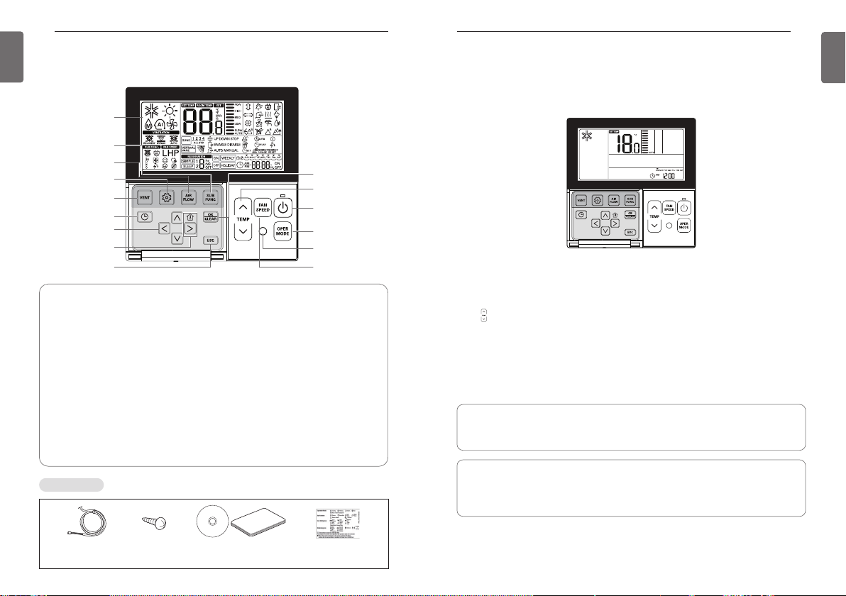
PART DESCRIPTION
Operation Display
Windows
Sub function Button
Airflow Button
Function Setting Button
Ventilation Button
Reservation Button
Up/Down/Left/Right
Room temperature
Accessories
Button
Button
ESC Button
Operation Display Windows : Displays the status of operation and settings
Ventilation Button : For interlocking operations of air-conditioner and ventilator
Function Setting Button : To select the additional operations function
Airflow Button : To select the airflows
Sub function Button : To select the additional operations function
Reservation Button : To program the schedule
Up/Down/Left/Right Button : To change the settings in the menu
Room temperature Button : To check the indoor temperature
ESC Button : To exit from the menu
Set/Cancel Button : To save the settings in the menu
Temperature Control Button : To change the desired temperature
Fan Speed Button : To select the fan speed
On/Off Button : To turn on/off with a remote controller
Mode Selection Button : To select the operating mode
Wireless Remote Controller Receiver
Set/Cancel Button
Temperature
Control Button
On/Off Button
Operation Mode
Selection Button
Wireless Remote
Controller Receiver
Fan Speed Button
OWNER’S INSTRUCTION
Standard Operation – Standard Cooling
A pleasant and fresh breeze cools off the room.
Press 2button in the remote controller to begin cooling.
- The initial temperature for cooling is set at 18°C by default.
- The desired temperature can be reached by 1°C or 0.5°C depending on the type of Indoor Unit.
Press button to set the desired temperature below the indoor temperature.
J button to see the indoor temperature.
- Press
h If the desired temperature is set above the indoor temperature, cool air will not blow out but
only fan will work instead.
Press
button during operation to stop cooling.
2
What is a 3-minute delay function?
A cool air will not blow out immediately after stopping cooling in order to protect a compressor. After 3 minutes, the cool air will blow out as the compressor runs.
• The range of the desired temperature is 18°C~30°C for cooling.
(when it is connected to product supporting cooling 16°C control, you can select the desired
temperature in 60~86°F(16~30°C).)
• 5°C is recommended for the difference between indoor and outdoor temperature.
Connecting Cable
1 EA, 10m
Screw (4 EA) Owner's /
Installation manual
Inform label
(8EA-8Languages)

OWNER’S INSTRUCTION
8
ENGLISH
OWNER’S INSTRUCTION
9
ENGLISH
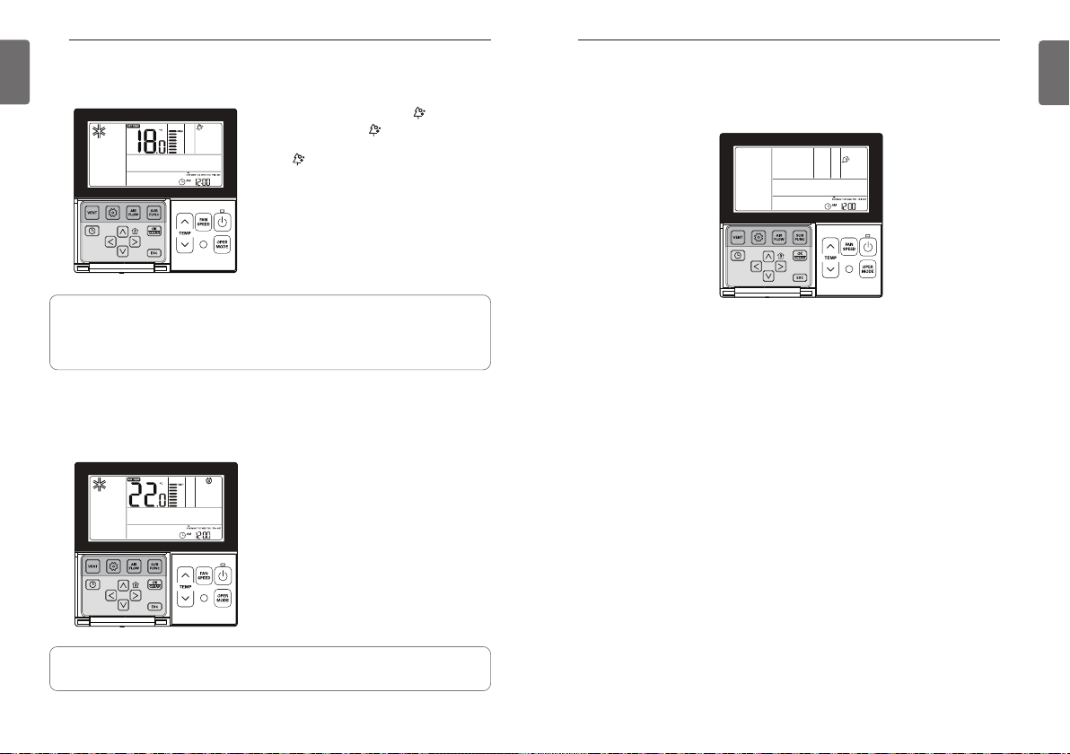
Standard Operation – Power Cooling
It cools off faster and more powerfully.
Press 2button to turn on the indoor.
button during cooling and it will move to “Po” and start power cooling.
Press
N
h Some units run the power cooling after power breeze.
Press
button during operation to cancel the power cooling and run the fan speed automati-
N
cally.
What is a power cooling?
Desired temperature: (actual temperature 18°C )
Fan speed: Power breeze
Breeze direction: cooling position
h Some units do not have power cooling function.
Running to cool down the indoor
temperature quickly.
Standard Operation – Heating Mode
A warm breeze blows out to the room.
Press 2button in the remote controller, and press Pbutton to select heating.
- The initial temperature for heating is set at 30°C by default.
- The desired temperature can be reached by 1°C or 0.5°C depending on the type of Indoor Unit.
Press button to set the desired temperature above the indoor temperature.
- If the indoor temperature is set above the desired temperature, warm air will not blow out but
only fan will work instead. (Press
Press 2button during operation to cancel heating.
• The range of the desired temperature is 16°C~30°C for heating.
• Heating applies only to cooling/heating models.
Heating will not work in the cooling only models.
J button to see the indoor temperature.)
OWNER’S INSTRUCTION
10
ENGLISH
OWNER’S INSTRUCTION
11
ENGLISH
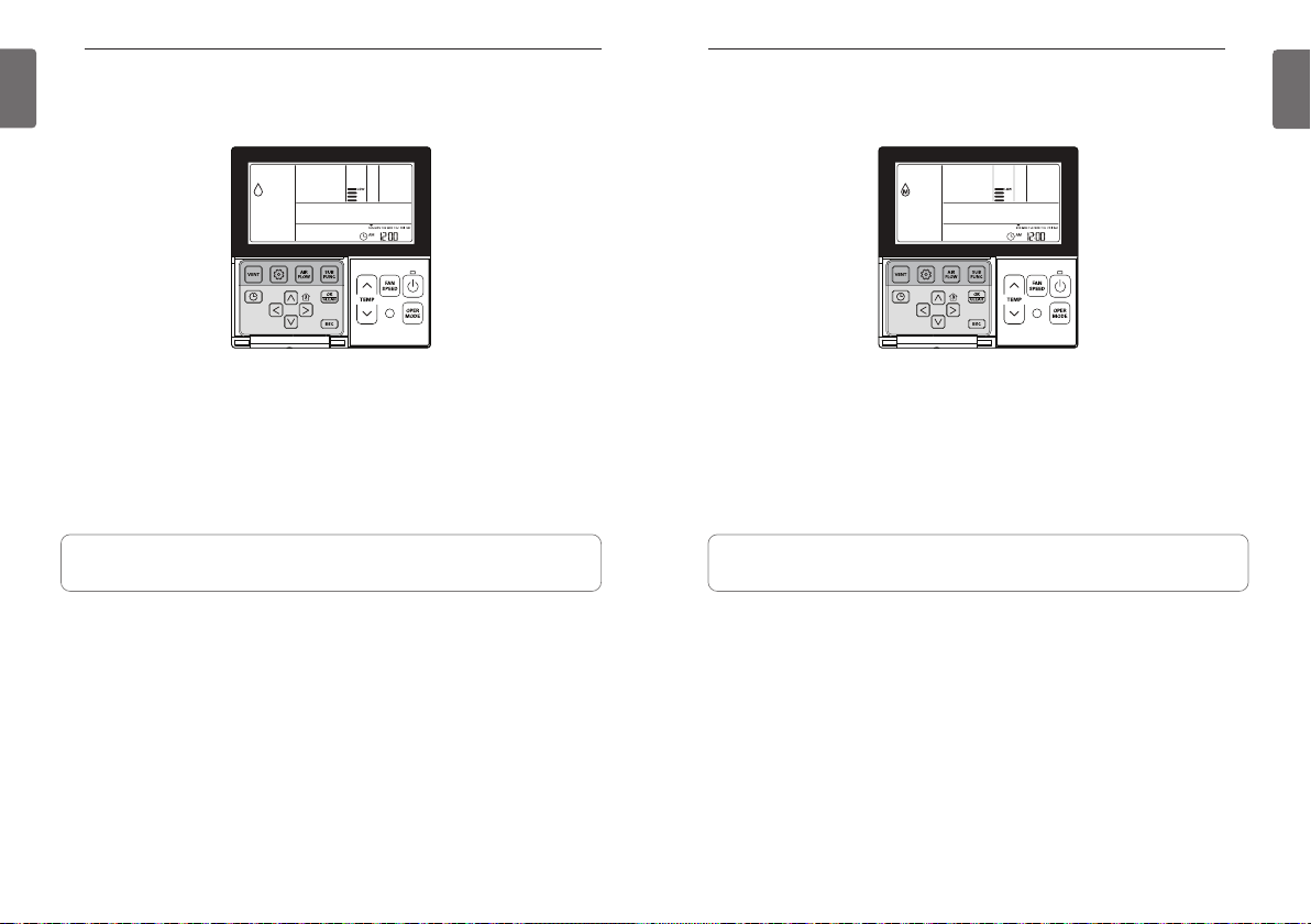
Standard Operation – Dehumidifying Mode
It removes moisture while cooling gently.
Press 2button.
button to select Dehumidify.
Press
P
- The temperature cannot be changed during dehumidification.
button repeatedly to adjust airflow SLOW → LOW → MED → HIGH → AUTO.
N
Press
- The initial fan speed in dehumidifying mode is set at ‘Low’.
• Using this function in the rainy season or high humidity, you can operate simultaneously
dehumidifier and cooling mode to remove humidity effectively.
• The menu of fan speeds may vary depending on the product type.
Standard Operation – Monsoon Dehumidifying Mode
This is monsoon region-specific dehumidification function.
Press 2button.
button to select Dehumidify.
Press
P
- The temperature cannot be changed during dehumidification.
button repeatedly to adjust airflow SLOW → LOW → MED → HIGH → AUTO.
N
Press
- The initial fan speed in dehumidifying mode is set at ‘Low’.
• Using this function in the rainy season or high humidity, you can operate simultaneously
dehumidifier and cooling mode to remove humidity effectively.
• The menu of fan speeds may vary depending on the product type.

OWNER’S INSTRUCTION
When cold
When cool
When appropriate
When warm
When hot
12
ENGLISH
OWNER’S INSTRUCTION
13
ENGLISH
Standard Operation – Fan Mode
it circulate air at room temperature, without heating or cooling it.
Press 2button.
button to select Fan mode.
Press
P
Press Nbutton repeatedly to adjust wind powerfulness SLOW → LOW → MED → HIGH → AUTO.
- The compressor will not run in the Fan mode.
• It circulates the air without heating or cooling.
• The menu of fan speeds may vary depending on the product type.
Standard Operation – Auto Operation Mode
It automatically selects an operating mode.
Press 2button.
button to select Artificial intelligence Mode.
Press
P
The temperature can be adjusted as illustrated below for cooling/heating models.
◀ Display window (cooling/heating models).
For the cooling only models, press button to adjust the temperature range ‘-2’~’2’ starting at
‘0’.
◀ Display window (cooling model)
In the Auto Operation mode.
• You can use
• If it doesn’t operate as you desire, you can select the other operation mode manually.
N button.

OWNER’S INSTRUCTION
14
ENGLISH
OWNER’S INSTRUCTION
15
ENGLISH
Standard Operation – Temperature Setting / Room Temperature Check
Temperature Setting
The temperature can be controlled easily to the desired set point.
Press temperature control button to select the desired temperature.
Press the button to raise the temperature by 1°C.
Press and hold the button to raise the temperature by 1°C automatically.
Press the button to lower the temperature by 1°C.
Press and hold the button to lower the temperature by 1°C automatically.
• Pressing the J button displays the actual room temperature for a short period.
• The controller displays the selected temperature.
In the cooling mode
If the desired temperature is higher than the indoor temperature, cooling will not operate.
Set the desired temperature lower than the indoor temperature.
In the heating mode (cooling/heating models)
If the desired temperature is lower than the indoor temperature, heating will not operate.
Set the desired temperature higher than the indoor temperature.
Room Temperature Check
Press Jbutton to display the current temperature.
- It returns to the desired temperature after about 5 seconds.
The actual feel temperature and the indoor temperature displayed in the remote controller may not
h
be identical due to the inconsistent temperature distribution in a space where the unit is installed.
• The range of the desired temperature is 18°C~30°C for cooling, and 16°C~30°C for heating.
(When it is connected to product supporting cooling 16°C control, you can select the
desired cooling operation temperature in 16°C~30°C.)
• 5°C is recommended for the difference between indoor and outdoor temperature.
Standard Operation – Fan Speed / Airflow
Fan Speed
The fan speed can be adjusted easily to the desired set point.
Press Nbutton to select the desired wind powerfulness.
- Press
N button repeatedly to adjust wind powerfulness SLOW → LOW → MED → HIGH
→ POW → AUTO.
- The menu of fan speeds may vary depending on the product type.
- See the product manual for more details.
Ex) Fan speed selection
Airflow
Wind direction can be adjusted easily to the desired set point.
Press
button to select the desired wind
D
direction.
- Press Airflow button to select the comfortable draft of air direction →
Up/Down/Left/Right → Left/Right →
Up/Down → upper air draft → down air draft
- The menu of wind directions may vary
depending on the product type.
- See the product manual for more details.
h If you select upper air draft or down air
draft, the wired remote controller will display the below
Ex) Wind direction selection
Airflow Remote Controller Display Window
Comfortable wind
Up/Down/Left/Right (ON simultaneously)
Left/Right
Up/Down
upper air draft
down air draft
OWNER’S INSTRUCTION
16
ENGLISH
OWNER’S INSTRUCTION
17
ENGLISH
Sub Function – Plasma Purification
Air purifying function cleans the air in the room.
Press Kbutton repeatedly until icon displays.
Press Kbutton when icon blinks to select or
cancel the purifying function.
h The icon will be displayed in case of setting
option and disappear in reverse case.
Press
L button to exit the setup mode.
If no button is selected for about 25 seconds after
h
setup, it exits the setup mode automatically.
h If the K button is not selected before you exit,
the changes will not apply.
h Some products may not include Air purifying function because it is an additional function.
h Air purifying is available only when the unit is running.
h If you want to run the air purifying only, press Sub function button in the Fan mode and
select Plasma Purification.
Sub Function – Energy-Saving Cooling Operation
Energy-saving cooling is a function to improve the energy-saving capacity and comfort by adjusting the desired temperature in the cooling mode.
Press Cbutton repeatedly until G icon displays.
Press Kbutton when G icon blinks to set or cancel the Energy-saving function.
h The G icon will be displayed in case of setting
option and disappear in reverse case.
Press
button after setup.
L
h
If no button is selected for about 25 seconds after
setup, it exits the setup mode automatically.
h If the K button is not selected before you exit,
the changes will not apply.
Sub Function – Manual Settings for Robot Cleaning
Robot Cleaning is a function that a built-in cleaner performs a filter cleaning automatically when
air-conditioner runs for the scheduled hours.
This function can be set in 30 seconds after the unit stops.
Press Cbutton repeatedly until Xicon displays.
Press Kbutton when Xicon blinks to set or cancel the Robot Cleaning function.
h The
icon will be displayed in case of setting option and disappear in reverse case.
X
h Robot Cleaning icon disappears automatically when cleaning is done.
h In order to cancel Robot Cleaning function manually, press Sub function button repeatedly until
the Robot Cleaning mode in the menu, and press
tion.
button after setup.
L
Press
h
Some products may not include Robot Cleaning function.
h If the K button is not selected before you exit, the changes will not apply.
K button to cancel Robot Cleaning func-
h Energy-saving function is available only in the cooling mode.
h Some products may not include Energy-saving function.

OWNER’S INSTRUCTION
18
ENGLISH
OWNER’S INSTRUCTION
19
ENGLISH
Sub Function – Electric Heater
It is a function to amplify the heating capacity by running an electric heater in the heating mode.
This function can be set only in the heating mode.
Press Cbutton repeatedly until 0icon displays.
Turn on/off electric heater by pressing Kbutton.
h The 0 icon will be displayed in case of setting option and disappear in reverse case.
button after setup.
L
Press
h
If no button is selected for about 25 seconds after setup, it exits the setup mode automatically.
h If the K button is not selected before you exit, the changes will not apply.
• Heater function is additional function and it only operates in selected models.
• The indoor unit product with Auxiliary Heater function set automatically displays (0) icon during
the AUXILIARY HEATING OPERATION.
When using non-heat recovery out door unit , emergency heater can be turned on for simultaneous heating and cooling. Indoor unit with the emergency heater must be turned OFF for simultaneous cooling and heating
Emergency heater can be turned on while in error code in case of emergency. Electric heater icon
is displayed on LCD display window with error code when emergency heater is on while in error
h
Exception case: Error code 1,3,9,10
h
If the previous mode of the Indoor unit is COOL, DRY or FAN ONLY mode, heater must be
turned on manually.
Sub Function – Humidifier
It is a function to run the built-in humidifier when the air in the room is dry.
Press Cbutton repeatedly until Humidifier
icon displays.
Turn on/off Humidifier by pressing
h The
I icon will be displayed in case of setting
option and disappear in reverse case.
Press
button after setup.
L
h
If no button is selected for about 25 seconds after
setup, it exits the setup mode automatically.
h If the K button is not selected before you exit,
the changes will not apply.
• Some products may not include humidifying function.
Sub Function – Mosquito Away
Only products with mosquito away function can use this.
Press Cbutton repeatedly until mosquito away
icon displays.
Turn on/off mosquito away function by pressing
button.
K
h The icon will be displayed in case of setting
option and disappear in reverse case.
Press
button after setup.
L
h
If no button is selected for about 25 seconds after
setup, it exits the setup mode automatically.
h If the K button is not selected before you exit,
the changes will not apply.
K
I
button.
• Some products may not include mosquito away function.

OWNER’S INSTRUCTION
20
ENGLISH
OWNER’S INSTRUCTION
21
ENGLISH
Sub Function – Himalaya Cooling
Only products with Himalaya Cooling function can use this.
Press Cbutton repeatedly until Himalaya cooling icon displays.
Turn on/off Himalaya cooling function by pressing
h The icon will be displayed in case of setting option and disappear in reverse case.
Press
button after setup.
L
h
If no button is selected for about 25 seconds after setup, it exits the setup mode automatically.
h If the K button is not selected before you exit, the changes will not apply.
• Some products may not include Himalaya cooling function.
K
button.
Sub Function – Fan Auto
It is the function that operates the fan when the outdoor unit is running. Only indoor units with
fan auto function can use this.
Press Cbutton repeatedly until fan auto
icon displays.
button.
K
• Some products may not include this function.
Turn on/off fan auto by pressing
h The icon will be displayed in case of setting
option and disappear in reverse case.
Press
button after setup.
L
If no button is selected for about 25 seconds after
h
setup, it exits the setup mode automatically.
h If the K button is not selected before you exit,
the changes will not apply.
Sub Function – Setting method for Comfort cooling
Comfort cooling is the function to keep the comfortable sensation by controlling the cooling
strength automatically without turning off the power of the product even after room temperature
reaches the desired temperature selected.
Press the Additional operation button until the icon of Comfort cooling is displayed.
Comfort cooling icon is blinking on the display screen, and if K
Comfort cooling icon is fixed and the function is set.
button to exit the setting mode.
L
Press the
button is pressed at this time,

OWNER’S INSTRUCTION
(Vane Number)
(Vane angle set point)
22
ENGLISH
Function setting – Vane Angle Control Function setting – Zone Control
You can adjust the angles of air flow.
You can turn on/off the zones by used of it.
OWNER’S INSTRUCTION
23
ENGLISH
Press Bbutton.
Press
button repeatedly to select the Vane Angles Setting in the menu.
B
Select the Vane number using HIbutton.
h Vane Number: No.1, No.2, No.3, No.4, ALL, Standard.
- The selected vane activates. Verify the active vane.
- Select ‘All’ to program the angle of all the vanes.
- Select ‘Standard’ to program as the factory default settings.
Select the vane angle using FGbutton, and press
- The range of vane angles setting can be changed to 5 levels or 6 levels
according to the product.
- When selecting ‘Standard’ for Vane number, the vane angle does not move.
Program the vane angles for the remaining vanes as the same as above.
h Some products include only No.1 and No.2 vanes.
Press
L button to exit after setup.
h If no button is selected for about 60 seconds after setup, it exits the setup
mode automatically.
h If the
K button is not selected before you exit, the changes will not
apply.
K
button.
Press Bbutton repeatedly until icon flash.
Press H I button to select the zone that which one you want to
turn on/off.
button to turn on/off zone.
K
Press
Press H I button to select other zones if you want.
Then, Press
above.
Press
without any input after 60 seconds.
h When exiting without pressing set button, the manipulated
value is not reflected.
button to turn on/off that zone as mentioned
K
button to exit or system will automatically release
L

OWNER’S INSTRUCTION
24
ENGLISH
OWNER’S INSTRUCTION
25
ENGLISH
Function setting – Elevation Grill
This function is to run the elevation grill to clean the filter of indoor unit.
Press Bbutton repeatedly until Vicon is blinking.
button. DOWN icon displays and the elevation
Move to DOWN using HIbutton, and press
grill will descend.
When the elevation grill descends to the desired point, move to ‘Stop’ icon using HIbutton
and press
When filter cleaning is finished, fix the filter to the gill, and move to UP icon using HIbutton.
And press Kbutton to ascent the elevation grill.
Press
h
If no button is selected for about 60 seconds after setup, it exits the elevation grill mode automatically.
h If the K button is not selected before you exit, the changes will not apply.
button to stop the elevation grill.
K
button to exit after setup.
L
K
Function setting – Auto Cleaning
Auto cleaning is a function to remove moisture or mold after turning off the cooling system by
drying the inside of indoor unit.
Press Bbutton repeatedly to select Auto cleaning in the menu.
icon will display and the current status of ENABLE or DISABLE icon will blink.
J
Move to ENABLE using HIbutton, and then ENABLE icon will blink. Press K
the auto cleaning function.
When returning to DISABLE, press HIbutton to select DISABLE icon. And then press
ton cancel the auto cleaning function.
Press
L to exit after setup.
h
If no button is selected for about 60 seconds after setup, it exits the setup mode automatically.
h If the K button is not selected before you exit, the changes will not apply.
• Some products may not include auto-drying function.
button to set
K
but-
• The elevation grill function is available only in the indoor unit with a built-in elevation grill.

OWNER’S INSTRUCTION
26
ENGLISH
OWNER’S INSTRUCTION
27
ENGLISH
Function setting – Automatic Setting for Robot Cleaning
Robot Cleaning is a function that a built-in cleaner performs a filter cleaning automatically when
air-conditioner runs for the scheduled hours.
It programs the robot cleaning function runs manually or automatically.
Press Bbutton repeatedly until Xicon is blinking.
Move to AUTO icon using HIbutton, and press Kbutton to select the automatic robot cleaning function.
MANUAL
When returning to the manual robot cleaning, press HIbutton to move to
press Kbutton to select the manual robot cleaning function.
button to exit after setup.
Press
L
h
If no button is selected for about 60 seconds after setup, it exits the setup mode automatically.
h If the K button is not selected before you exit, the changes will not apply.
• Some products may not include robot cleaning function.
icon and
Function setting – Child Lock
This function is to lock the buttons to prevent children or others from careless using.
Press Bbutton repeatedly until icon is blinking.
Move to icon using HIbutton.
The icon will blink, and press Kbutton to set the lock function.
To cancel the lock function, press HIbutton to move to icon. And then press
button to exit after setup.
Press
L
h
If no button is selected for about 60 seconds after setup, it exits the setup mode automatically.
h If the K button is not selected before you exit, the changes will not apply.
K
button.

OWNER’S INSTRUCTION
28
ENGLISH
OWNER’S INSTRUCTION
29
ENGLISH
Function setting – Filter Sign Clear
This function is to cancel the filter indicator for filter cleaning of indoor unit.
Press Bbutton repeatedly until icon is blinking.
If the system includes a displaying function of the time remaining until next filter cleaning, it will
display the remainng time in the current time section.
button to cancel the filter cleaning sign.
When the filter cleaning indicator blinks, press
• Dust in the filter may reduce cooling/heating efficiency and cause high electricity bill.
Therefore, be sure to clean the filter whenever cleaning time is expired.
h Filter cleaning indicator is automatically cancelled without any separate cancellation after cer-
tain period of time.
K
Function setting – Changing Current Time
button repeatedly to select the time setting in the menu.
B
Press
‘Time Setting’ icon will display and day of the week will blink in the current time section.
Move to ‘Day’ using HIbutton.
Press Gbutton after setting the day to move to the ‘AM/PM’ setting mode.
Press FGbutton to set ‘AM/PM’.
Move to ‘Hour’ section using HIbutton. ‘Hour’ section will blink.
Press FGbutton to set the current hour.
Move to ‘Minute’ section using HIbutton. ‘Minute’ section will
blink.
Press FGbutton to set the current minute.
When the day/hour/minute setting is finished, press K button to complete the current time setting.
h If pressing other buttons during the current time setting, it will cancel all the changes made
and exit the time setting mode.
h If the
K button is not selected before you exit, the changes will not apply.

OWNER’S INSTRUCTION
22°C
25°C
temperature(°C)
19°C
time
start cooling start cooling
start heating
003 248.7 kWh
30
ENGLISH
OWNER’S INSTRUCTION
31
ENGLISH
Function setting – Change Temperature
Change temperature is a function to automatically change the temperature between cooling/heating according to the temperature in the Auto operation mode.
Press Bbutton repeatedly to select the change temperature function in the menu.
icon will display and the changed temperature will blink in the temperature display section.
G
Press FGbutton to change the temperature set value.
h Range of change temperature: programmable within 1~7
When the desired temperature is displayed, press
Press
button to exit after setup.
L
h If no button is selected for about 1 minute after setup, it exits the setup mode automatically.
h If the
K button is not selected before you exit, the changes will not apply.
h This function is available only for cooling/heating system.
Example of Change Temp
Conditions
1) Mode: Auto operation
2) Desired temperature: 22°C
3) Change temperature: 3°C
button to complete the setting.
K
Function setting – Power Consumption
Press Bbutton repeatedly to select the power consumption in the menu.
icon will display and the accumulated power consumption will display in the temperature and
the current time display section.
to exit.
L
Press
If no button is selected for about 1 minute after setup, it exits the setup mode automatically.
Ex) when the accumulated power consumption is 3248.7 kWh
• Some product may not include the power consumption display function
• This function is available only when PDI is installed.
If it falls under the conditions described above, it will run as shown in the graph.

OWNER’S INSTRUCTION
Ex) Model Information
Outdoor Unit CapacityIndoor
Unit
32
ENGLISH
Function setting – Indoor/Outdoor Unit Model Information
<Indoor/Outdoor Unit Model Information Table>
Category Display Values
Outdoor
Unit
No. Model No. Model No. Model No. Model
0 Multi-V 1 Multi 2 Single 3 Multi-V
OWNER’S INSTRUCTION
33
ENGLISH
Press Bbutton repeatedly to select the Indoor/outdoor unit model information in the menu.
icon will display and the Indoor/outdoor unit model information will display in the temperature
display section.
to exit.
L
Press
If no button is selected for about 1 minute after setup, it exits the setup mode automatically.
• Some product may not include the indoor/outdoor unit model information function.
Indoor
Unit
Capacity
Data
unavailable
(common)
No. Model No. Model No. Model
0 CST 5
1 Duct 6 Console B
2 CVT 7
3 PAC 8
4 RAC 9 AWHP E FAU
No. Capacity No. Capacity No. Capacity No. Capacity
0 5k 4 15k 8 36k C 76k
Multi-V
Multi-V
-
1 7k 5 18k 9 42k D 96k
2 9k 6 24k A 48k E -
3 12k 7 28k B 54k F -
0 5k 4 12k 8 20k C -
1 7k 5 14k 9 24k D -
Multi
2 8k 6 15k A 30k E -
3 9k 7 18k B 36k F -
0 9k 4 24k 9 54k 55k -
1 12k 5 30k A 60k 62k -
Single
2 18k 6 36k B 70k - -
3 21k 7 42k C 85k - -
0 21k 4 - 8 - C -
1 30k 5 - 9 - D -
2 60k 6 - A - E -
3 - 7 - B - F -
Direct
Expansion
Ventilation
Single
Package
General
Ventilation
A
C Showcase
D VAHU
Hydrokit for
medium
temperature
Hydrokit for
high temper-
ature

OWNER’S INSTRUCTION
34
ENGLISH
OWNER’S INSTRUCTION
35
ENGLISH
Function Setting – WLAN(Wireless LAN) Module Access Point
mode
It is the function to operate WLAN (Wireless LAN) module connected to the product in access
point mode. This function is available for particular models to apply WLAN Module.
Refer to the installation manual of product whether available or not.
Push the Bbutton repeatedly until the term of 'AP' is displayed on the screen.
K
button.
Press the
h After setup, it automatically gets out of setup mode.
While WLAN module is operating in access point mode, the term of 'AP' blinks on the screen of
wired remote controller.
- It will take approx. five (5) seconds before WLAN module operates in access point mode.
- In the case WLAN module is not installed, the access point mode does not work.
Function setting – Smart Load Control
Smart Load Control is the function to operate by calculating the necessary efficiency from the
indoor and outdoor air temperature and humidity.
The corresponding function setting is available when connecting the products designated as outdoor unit Function setting master.
Press the Bbutton.
If Bbutton is pressed repeatedly, it is moved to Smart Load Control stage setting menu.
At this time, Smart Load Control icon is displayed and the setting value on the temperature display area
is flickering.
Press FGbutton and select Smart Load Control stage setting value.
h Smart Load Control stage can be set from 0 to 4, and it controls the strength of the cooling or heat-
ing function at the initial stage of operation.
0 : Function not used
1 : Smooth mode
2 : Normal mode
3 : Peak mode
If desired Smart Load Control stage value is displayed, press Kbutton to complete setting.
If setting is completed, press
h If there would be no button input for about 1 minute after setting, it exits from the setting mode auto-
matically.
h If it is exited without pressing setting button, the handled value is not reflected.
When Smart Load Control is operated, Smart Load Control operation status is displayed as below.
4 : Load Matching Control mode
button.
L
Smart Load Control function may not work on some products.
Step 4 settings may not be available on some indoor unit products.

OWNER’S INSTRUCTION
36
ENGLISH
OWNER’S INSTRUCTION
37
ENGLISH
Programming – Simple Reservation
Simple reservation function can be scheduled to stop while the system is in operation or to run
while the system is not in operation.
Press Ebutton to enter the programming mode.
Press Ebutton repeatedly to select ‘SIMPLE.’
icon will blink and the scheduled time ‘0’ will display.
Y
Press FGbutton to program the scheduled time.
The scheduled time can be programmed from 1 hour up to 7 hours.
Press
button when the simple programming is finished.
K
- When the schedule setting is completed,
L to exit.
Press
h
If no button is selected for about 25 seconds after setup, it exits the setup mode automatically.
h If the K button is not selected before you exit, the changes will not apply.
For the simple programming, if the scheduled time expires, the system will run or stop automatically.
Y icon will display in the lower LCD screen.
Programming – Sleep Reservation
Sleep Reservation is a function that the air-conditioner runs in the sleep mode or stops after certain
period of time while you are sleeping. When sleep mode is programmed after connecting to a ventilator, and in a certain period of time after sleep mode operation, only sleep mode will be cancelled.
Press Ebutton to enter the programming mode.
button repeatedly to select ‘SLEEP’. [icon will blink and the
Press
E
scheduled time will display.
Press FGbutton to program the scheduled time.
The scheduled time can be programmed from
1 hour up to 7 hours.
button when the SLEEP programming is completed.
Press
K
to exit.
L
Press
h If no button is selected for about 25 seconds after setup, it exits the setup mode automatically.
h If the K button is not selected before you exit, the changes will not apply.
- When the Sleep schedule is cancelled, [icon will disappear.
NOTE
!
Set the moderate amount of time for SLEEP mode. (Excessive cooling is harmful for your health.)
• The desired temperature in the remote controller and the unit may not be identical because the
SLEEP mode runs automatically adjusting the desired temperature for a pleasant cooling.
• Some product without a temperature control by 0.5°C operates OFF reservation instead of
SLEEP reservation.

OWNER’S INSTRUCTION
38
ENGLISH
OWNER’S INSTRUCTION
39
ENGLISH
Programming – ON Reservation
It turns ON automatically at the time programmed.
Press Ebutton to enter the programming mode.
button repeatedly to select ‘ON’.
Press
E
‘ON’ icon and ‘AM’ icon will blink.
Set ‘AM/PM’ using FGbutton.
Move to ‘Hour’ using HIbutton,
and set the ‘Hour’ using FGbutton.
Move to ‘Minute’ using HIbutton,
Set the ‘Minute’ using FGbutton.
button when the ON reservation is completed.
K
Press
Press
L to exit.
h If no button is selected for about 25 seconds after setup, it exits the setup mode automatically.
h If the
K button is not selected before you exit, the changes will not apply.
- When the schedule setting is completed,
the system will run at the time programmed.
- When the ON schedule is cancelled,
Z icon will display in the lower LCD screen, and
Z icon will disappear.
Programming – OFF Reservation
It turns OFF automatically at the time programmed.
Press Ebutton to enter the programming mode.
button repeatedly to select ‘OFF’.
Press
E
‘OFF’ icon and ‘AM’ icon will blink.
h You can program the ‘AM/PM’, ‘Hour’ and ‘Minute as the same way as the ON reservation.
Press
button when the OFF reservation is completed.
K
to exit.
Press
L
h If no button is selected for about 25 seconds after setup, it exits the setup mode automatically.
h If the
K button is not selected before you exit, the changes will not apply.
- When the schedule setting is completed,
the system will stop at the time programmed.
- When the schedule is cancelled,
\ icon will display in the lower LCD screen, and
\ icon will disappear.

OWNER’S INSTRUCTION
Turning on time
Under bar: the indication that there is weekly
reservation for corresponding day.
Reservation number
Turning off time
40
ENGLISH
Programming – Weekly Reservation
You can program daily schedule by week.
Weekly reservation keeps operating until before you cancel it once you setup.
Press E button to enter the programming mode.
h Weekly reservation can be programmed 2 schedules for one day, and up to 14 reservations for
a week.
Ex) To program [② Tuesday AM 11:30 ON~PM 12:30 OFF], follow the instructions as below.
Change the time using FGbutton.
- You can program the ‘Hour’ from 1 hour up to 12 hours.
Move to ‘Minute’ section in the ON setting using Ibutton.
When the ‘Minute’ button is blinking, press Up/Down button to set the ‘Minute’.
Move to ‘AM/PM’ section in the OFF setting using Ibutton.
- AM/PM setting is the same as the ON time setting.
Move to ‘Hour’ section in the OFF setting using Ibutton.
- This section is to program when system will turn OFF.
- When the ‘Hour’ button is blinking, set the ‘Hour’.
h Program the ‘Hour’ and ‘Minute’ as the same way as
the ON time setting.
OWNER’S INSTRUCTION
41
ENGLISH
Press Ebutton repeatedly to select ‘WEEKLY’.
will blink.
[
Select 1 or 2 using F G button.
h You can program 2 schedules per day such as
WEEKLY 1, WEEKLY 2.
Move to ‘Day’ using H I button.
When the ‘Day’ is blinking, set the day.
Day setting is available for Monday through Sunday.
Move to ‘AM/PM’ using Gbutton, and select AM/PM.
Move to ‘Hour’ section in the ON setting using Ibutton.
- This section is to program when the air-conditioner will
turn ON.
button Weekly Reservation programming is completed.
Press
K
Set the OFF time later than the ON time when programming the time for Weekly Reservation
h If programming the temperature using the Up/Down button for the desired temperature during
the weekly reservation, the system will be ON at the desired temperature.
- When desired temperature is not programmed, it is turned on automatically with desired temperature of previous operation.
h To cancel all the Weekly Reservation programmed,
- Press Set/Cancel button when the
h To cancel the weekly reservation individually,
- Select the day you want to cancel and set the ON time and OFF time identically, and press
Set/Cancel button.
[ icon is blinking.
< Weekly Reservation Description>

OWNER’S INSTRUCTION
42
ENGLISH
OWNER’S INSTRUCTION
43
ENGLISH
Programming – Holiday Reservation
The system will stop automatically on a set day.
Press Ebutton to enter the Schedule Programming mode.
button repeatedly to select ‘HOLIDAY’.
Press
E
Move to the ‘Day’ you want to set using HIbutton.
button.
Set or cancel HOLIDAY using FGbutton or
Ex) If Monday/Friday is programmed as HOLIDAY, ‘MON’, ‘FRI’ will disappear.
Press
L button to exit.
- Once set as HOLIDAYS, the system will stop automatically within 1 hour even after operating
the air-conditioner unless the HOLIDAYS schedule is cancelled.
K
Ventilation Product User Manual – Interlinked Air conditioner
and Ventilation
You can control the system by using a wired remote controller for an air conditioner indoor unit
interlocked with a ventilator.
- When applying power, the remote controller will work after recognizing the system (for about
30 seconds).
Single Operation Interlinked Operation
(General Ventilation Single Operation)
General
Ventilation
Direct
Expansion
Ventilation
h Connecting method is identical with the one in air conditioner instructions manual.
(See the Group control page in the Remote controller manual.)
Press
button on the wired remote controller to enter the ventilation control mode in order to
1
verify the ventilator’s operation.
In order to return to the air conditioner mode, press ‘Vent’ button in the ventilation mode.
- If no button is selected for more than 15 seconds in the ventilation mode, the system will automatically convert to air conditioner mode.
h The ventilators include general ventilators and direct expansion ventilators.
General Ventilation
Wired Remote
Controller
(Direct Expansion Ventilation
Single Operation)
Direct Expansion
Ventilation
Wired Remote
Controller
Fig 2-1. Air conditioner mode Fig 2-2. Vent mode
(General Ventilation Interlinked Operation)
Air
conditioner
Indoor unit
Wired Remote Controller
(Direct Expansion Ventilation
Interlinked Operation)
Air
conditioner
Indoor unit
Wired Remote Controller
General
Ventilation
Direct
Expansion
Ventilation

OWNER’S INSTRUCTION
→→→ →→→→
44
ENGLISH
OWNER’S INSTRUCTION
45
ENGLISH
Ventilation Product User Manual – Interlinked Operation with
General Ventilation
It can be used only when the air conditioner and the ventilator are interlocked. This function is to
cool off the air in the room using a ventilator while air conditioner function is operating.
Press 1button on the remote controller.
- It can be used only when the air conditioner and the general ventilator are interlocked.
Press
button in the Vent mode to run the ventilator.
2
button in the Vent mode to change the ventilation operation mode.
Press
P
-
Each time you press the button the mode will change in the order of Heat exchange → normal → auto.
h It only displays on the remote controller display when it is in ventilation mode, and it displays
the desired temperature when it returns to air condition mode.
Press
button in the Vent mode to change the fan speed.
N
- Each time you press the button the fan speed is selected in the order of low
-
If a CO2sensor is installed, you can select the fan speed in the order of low → high → power → auto.
How to convert to air conditioner mode
1) Auto conversion: if no button is selected for more than 15 seconds in the vent mode, the system will convert to air conditioner mode automatically.
2) Manual conversion: press the
1 button in the vent mode to convert manually.
→
high → power.
Ventilation Product User Manual – Single Operation with
General Ventilation
This function is to circulate the air in the room using a general ventilator.
Press 2button on the remote controller.
button to convert the ventilation mode.
Press
P
Vent mode
Heat exchange
Normal
Auto
In the case of heat exchange mode is shown below.
Press
N
- Each time you press the button the fan speed is selected in the order of low
-
If a CO2sensor is installed, you can select the fan speed in the order of low → high → power → auto.
Remote controller
display window
The fresh air entering the room is heated or cooled by the
air leaving the room. This mode is used when pre-heating
or pre-cooling improves comfort and reduces energy consumption.
The fresh air by-passes the heat exchanger and enters the
room at outdoor temperature.
The system selects Heat exchange or Normal automatically after comparing indoor and outdoor temperatures.
button in the Vent mode to change the fan speed.
Description
→
high → power.

OWNER’S INSTRUCTION
→→→ →→→→
46
ENGLISH
OWNER’S INSTRUCTION
47
ENGLISH
Ventilation Product User Manual – Interlinked Operation with
Direct Expansion Ventilation
It can be used only when the air conditioner and the direct expansion ventilator are interlocked.
Press 1button on the remote controller.
It can be used only when the air conditioner and the ventilator are interlocked.
Press
button in the Vent mode to run the ventilator.
2
Press
button in the Vent mode to change the vent mode.
P
-
Each time you press the button the mode will change in the order of Heat exchange → normal → auto.
h It only displays on the remote controller display when it is in ventilation mode, and it displays
the desired temperature when it returns to air condition mode.
Press
button in the Vent mode to change the fan speed.
N
- Each time you press the button the fan speed is selected in the order of low
How to convert to air conditioner mode
1) Auto conversion: if no button is selected for more than 15 seconds in the vent mode, the system will convert to air conditioner mode automatically.
2) Manual conversion: press the
1 button in the vent mode to convert manually.
→
high → power.
Ventilation Product User Manual – Single Operation with Direct
Expansion Ventilation
This function performs ventilation operation with cooling or heating at the same time using the
heat exchanger inside the direct expansion type ventilation product.
Press 2button on the remote controller.
- The direct expansion ventilator individual operation will be displayed as shown in the figure.
P button in the Vent mode to change the ventilation mode.
Press
Each time you press the button the mode will change in the order of Heat exchange → normal → auto.
-
Vent mode
Heat exchange Circulating the air in the room without any heat loss
Normal
Auto
In the case of heat exchange mode is shown below.
h The indicator of 88Seg is displayed when only the direct expansion ventilation is operating with
air conditioner OFF.
Press
P
- Each time you press the button the mode will change in the order of cooling → heating → auto → stop.
Press
N button to change the fan speed.
- Each time you press the button the fan speed is selected in the order of low
h In the Direct expansion ventilator individual operation, it is possible to select cooling or heating and
to adjust the desired temperature as well.
h See the Standard Operation – Temperature Setting for more information about the desired tempera-
ture adjustment.
Remote controller
display window
Circulating the air in the room without using an electric
heating exchanger
Circulating the air in the room by comparing the indoor/outdoor temperatures automatically
button to convert the operation mode.
Description
→
high → power.

OWNER’S INSTRUCTION
48
ENGLISH
OWNER’S INSTRUCTION
49
ENGLISH
Ventilation Product Additional Operations – Fast/Energy Saving
This function is to facilitate the ventilation function more efficiently by setting quick/energy-saving
mode in the additional functions of ventilator.
Fas t
It ventilates quickly.
Press Cbutton in the Vent mode.
- The additional vent mode converts Fast
Press
button when the icon blinks on the display screen.
K
Press
button to exit.
L
Energy Saving
It performs Energy-saving function while ventilating efficiently.
Press
in the Vent mode.
C
The additional vent mode converts Fast
Press
button when the Energy-saving icon blinks on the display screen.
K
Press Lbutton to exit.
h The additional mode of general ventilation and direct expansion ventilation is identical.
h The additional mode settings for air cleaner/heater/humidifier are as the same as the air condi-
tioner.
→
Energy-saving sequentially.
→
Energy-saving sequentially.
Ventilation Product Function Settings
Ventilation starts after delay time.
Delay time
Ventilation starts after delay time.
Press Bbutton.
Press Bbutton repeatedly to move to the dealy time in the menu.
The Cicon displays and blinks in the temperature display section.
Change the set value for delay time using F G button.
h The range of delay time settings : 00 ~ 60 (By 1 minute)
Press
button to complete the settings when the desired value for delay time displays.
K
button to exit.
L
Press
h If no button is selected for about 1 minute after setup, the system will exit automatically.
K button is not selected before you exit, the changes will not apply.
h If the
Lock, Filter Cleaning, Time Setting, Converting Temperature
h Refer to 'Function Settings - Child Lock’ part for lock function.
h Refer to 'Function Settings - Filter Sign Clear’ part for Filter Cleaning function.
h Refer to 'Function Settings - Changing Current Time’ part for Time Setting function.
h Refer to 'Function Settings - Change Temperature' part for Temperature Conversion function.

OWNER’S INSTRUCTION
Code value Set value
50
ENGLISH
Sleep Reservation
You can program a ventilator to run moderately while you are sleeping
Ventilation Product Installer Setting Functions Ventilation Product Reservation Settings
Press 1button to enter the ventilation mode.
OWNER’S INSTRUCTION
51
ENGLISH
Press Ebutton to enter the schedule programming mode.
button repeatedly to move to SLEEP in the menu.
Press
E
icon will blink and the scheduled time will display.
[
Set the scheduled time using F G button.
You can program the scheduled time from 1hour up to 12 hours.
Press Kbutton when the SLEEP schedule is programmed.
button to exit
L
Press
h If no button is selected for about 25 seconds after setup, the system will exit automatically.
h If the
K button is not selected before you exit, the changes will not apply.
- Once the schedule is programmed,
- [ icon will disappear when the schedule is cancelled.
If the SLEEP schedule is programmed, the system will run moderately during the scheduled
time.
[ icon will display in the lower part of LCD.
Simple, ON, OFF, Weekdays, Holidays Reservations
h Please refer to the Reservation Settings part of the air conditioner for Simple, ON, OFF,
Weekdays, Holidays Reservations
Press and hold Bbutton for more than 3 seconds to enter the installer settings mode.
- If pressing only once briefly, it will enter the user settings mode.
Make sure to press and hold for more than 3 seconds.
Once entered the installer settings mode, it displays the programmable data values in the lower
right of LCD screen.
• Some items in the menu may not be displayed depending on the product functions, or have
different name in the menu.
CAUTION
!
Installer setting is a mode to set the detailed functions of remote controller.
If the installer setting mode is set improperly, it may cause a break down, injury, or property
damage.
It must be set by a certified technician, and when it is installed without certified technician
or changed discretionally, all of the problems are the responsibilities of the installer, and we
do not provide service free of charge.

OWNER’S INSTRUCTION
Code value for
standard vent fan speed
Set value
❈ Set value
00 : Factory default
01 : 10% Increase
21 : 10% Decrease
22 : 20% Decrease
52
ENGLISH
OWNER’S INSTRUCTION
53
ENGLISH
Ventilation Product Installer Setting Functions – Ventilation Fan Speed
This function is to change the standard fan speed of ventilation.
Press and hold Bbutton for more than 3 seconds to enter the installer settings mode.
- If pressing only once briefly, it will enter the user settings mode.
Make sure to press and hold for more than 3 seconds.
button repeatedly to move to the fan speed settings in the menu as below.
Press
B
Select the fan speed mode using FGbutton.
Press
button to complete the settings when the standard vent fan speed is selected.
K
button to exit.
Press
L
h If no button is selected for about 25 seconds after setup, the system will exit automatically.
h If the
K button is not selected before you exit, the changes will not apply.
Different Mode Drive
Different mode drive appears when the Indoor Unit have different operating modes if several
Indoor Unit are installed for a single outdoor unit.
Different mode drive doesn’t appear in the cooling only models.
If an indoor unit is forced to run heating while several Indoor Unit are in a cooling operation with a
single outdoor unit, the system will not run heating.
If an indoor unit is forced to run cooling or dehumidifying while several Indoor Unit are in a heating operation with a single outdoor unit, the system will not run cooling or dehumidifying.
It indicates the outdoor is in a heating operation.
Press
button and the indoor unit will automatically run in the same operating mode as the
2
other Indoor Unit after about 5 seconds.

OWNER’S INSTRUCTION
54
ENGLISH
OWNER’S INSTRUCTION
55
ENGLISH
Self-diagnosis for Trouble Mode
It automatically runs a self-diagnosis when there is a trouble detected in the system.
It displays the troble mode number with maintenance CODE.
<Individual control>
<Group control>
h When detecting an error during group control, the system will
display as below.
<In case of CH05 ERROR, 4 letters C,H,0,5 will display one by one.>
In order to expedite a service, please remember the error number and provide it when consulting
an installer.
An emergency elevation grill can be operated even in the case of errors.
(Except the trouble mode number 03)
h If the centralized control lock or wired remote controller lock is programmed, this function will
not work.
h Some product may not include this function.
Oil Change Warning
Only products with GHP(Gas Heat Pump) Product can use this.
Once the operation hours of the outdoor unit passes 10,000hours, the oil change-Indicator alarm
occurs. When the alarm occurs, refer to the cover immediately to contact a service center in
order to change the oil.
• When the oil is not changed, an error will occur to make the product impossible to run.
Outage Compensation Function
If power supply fails due to outage or other reasons, the outage compensation function automatically retrieves the operating conditions previously programmed before the power failure. Thus,
you don’t need to press any buttons.
(Additional functions will not be retrieved automatically.)

INSTALLATION INSTRUCTION
Wall
Side
Wall
Side
Wall
Side
Wall
Side
<Connecting order>
<Separating order>
Please check if connector is normally connected.
Connecting cable
Indoor
Unit side
2
2
1
3
3
56
ENGLISH
INSTALLATION INSTRUCTION
Please fix tightly using provided screw after placing remote controller setup
board on the place where you like to setup.
- Please set it up not to bend because poor setup could take place if setup board bends.
Please set up remote controller board fit to the reclamation box if there is a reclamation box.
- Install the product so as not to make a gap with the wall side and to prevent shaking after the
installation.
INSTALLATION INSTRUCTION
Please fix remote controller upper part into the setup board
attached to the surface of the wall, as the picture below, and
then, connect with setup board by pressing lower part.
- Please connect not to make a gap at the remote controller and
setup board’s upper and lower, right and left part.
- Before assembly with the installation board, arrange the Cable
not to interfere with circuit parts.
When separating remote controller from setup board, as
the picture below, after inserting into the lower separating
hole using screw driver and then, spinning clockwise,
remote controller is separated.
- There are two separating holes. Please individually separate
one at a time.
- Please be careful not to damage the inside
components when separating.
Please connect indoor unit and remote controller using connection cable.
57
ENGLISH
Can set up Wired remote controller cable into three directions.
- Setup direction: the surface of wall reclamation, upper, right
- If setting up remote controller cable into upper and right side, please set up after removing
remote controller cable guide groove.
h Remove guide groove with long nose.
① Reclamation to the surface of the wall
② Upper part guide groove
③ Right part guide groove
<Wire guide grooves>
DC 12 V Red
Signal Yellow
GND Black
CAUTION
!
• Installation work must be performed in accordance with the national wiring standards by
authorized personnel only.
• Installations must comply with the applicable local/national or international standards.
• Apply totally enclosed noncombustible conduit (metal raceway) in case of local electric &
building code require plenum cable usage.
Please use extension cable if the distance between wired remote controller and
indoor unit is more than 10m.
CAUTION
!
When installing the wired remote controller, do not bury it in the wall. (It can cause damage in
the temperature sensor.)
The total cable length must not exceed 50m. (It can cause communication error.)
• When installing the extension cable, check the connecting direction of the connector of the
remote controller side and the product side for correct installation.
•
If you install the extension cable in the opposite direction, the connector will not be connected.
• Specification of extension cable: AWG 24, 3 conductor or above

INSTALLATION INSTRUCTION
Code value Set value
Master Slave Slave
GND
GND
DC 12 V
Signal wire
Signal wire
GND
DC 12 V
B Y R B Y R
MASTER SLAVE
Signal wire
GND
DC 12 V
Signal wire
#3 switch OFF: Master
(Factory default setting)
#3 switch ON: Slave
58
ENGLISH
INSTALLATION INSTRUCTION
59
ENGLISH
Group Control
When installing more than 2 units of air conditioner to one wired remote controller, please
connect as the right figure.
• If it is not event communication indoor unit,
set the unit as slave.
• Check for event communication through the
product manual.
When controlling multiple indoor units with event communication function with one remote controller, you must change the master/slave setting from the indoor unit.
- After completion of master/slave setting of indoor unit and turn off the unit, 1 minute later turn
it on again.
- For ceiling type cassette and duct product group, change the switch setting of the indoor PCB.
- For wall-mount type and stand type product, change the master/slave setting with the wireless
remote controller. (Refer to wireless remote controller manual for detail)
h When installing 2 remote controllers to one indoor unit with event communication function, set
the master/slave of the remote controller. (Refer to remote controller master/slave selection)
When controlling the group, some functions excluding basic operation setting, fan level
Min/Mid/Max, remote controller lock setting and time setting may be limited.
When installing more than 2 wired remote controllers to one air conditioner, please connect as
the right picture.
• When installing more than 2 units of wired
remote controller to one air conditioner, set one
wired remote controller as master and the others
all as slaves, as shown in the right picture.
• You cannot control the group as shown in the
right for some products.
• Refer to the product manual for more detail.
• When controlling in groups, set the master/slaver of the remote controller. Refer to Installer
setting section on how to set master/slave for more detail.
<When simultaneously connecting
2 sets of wired remote controller>
Installer Setting – Installer Setting Mode Approach
Keep pressing(over 3 seconds) the B button repeatedly to scroll to the required function as
described in the Installer setting code table below. Use the arrow buttons to select the required value,
and then press the
installer mode will cease automatically if no buttons have been pressed for about 25 seconds.
Once entered the installer settings mode, it displays the programmable data values in the lower
right of LCD screen.
• Some items in the menu may not be displayed depending on the product functions, or have
different name in the menu.
!
Installer setting is a mode to set the detailed functions of remote control.
If the installer setting mode is set improperly, it may cause a break down, injury, or property
damage.
The installation requires an expertise and must be performed by one of our service centers
or expert installer providers.
The person who performed an installation takes responsibility for any troubles associated
with the installation, and in this case, service will be charged.
CAUTION
K
button. You can leave the installer menu by pressing L. Alternatively, the

INSTALLATION INSTRUCTION
60
ENGLISH
Installer Setting Code Table
<General air conditioner product code table>
Code Function Value
01 Test run 01 : Set
02 Address Setting 00~FF : Address
03 E.S.P. Value
04 Thermistor 01 : Remote control, 02 : Indoor unit, 03 : 2TH
05 Ceiling Height 01 : Low, 02 : Med, 03 : High, 04 : Very High
06 Static Pressure 01 : V-H, 02 : F-H, 03 : V-L, 04 : F-L
07 Master Setting
08 Override Setting 00 : Slave, 01 : master
09 Dry Contact 00 : Auto-Off, 01: Auto-On
10 Release 3 Min. Delay 01 : Set
11 Zone State 01 : Variable, 02 : Fixed
12 Celsius Fahrenheit Switching
13 Zone Type 00 : Zone Controller, 01:Damper Controller
14 Zone Number 02~04(Zone number)
17 Centigrade Control Settings 00 : 1 °C Control , 01 : 0.5 °C Control
18 Emergency Heater Setting
19
Function Setting for Group Control
20 Plasma
21 Electric heater
22 Humidifier
23 Elevation Grill
24 Ventilation Kit
25 Auxiliary Heater
26 Indoor unit address checking
Settings for Refrigerant
29
Leak Detector Installation
32 Static Pressure step
<ESP Step> <ESP Value> <Example>
01 : VeryLow 0 ~ 255
02 : Low
03 : Med
04 : High
05 : Very High
00 : Slave h
00 : Group setting 01 :
00 : Celsius, 01:Fahrenheit (Optimized only for U.S.A)
Select mode Setup Low Ambient Setup FAN
00 : not use 00 : not use 0 : fan off
01 : use 01~03: Setting step 1 : fan on
01 : Not in use, 02 : In use
00 : Not Installed
01 : Installed
00 : Not Installer
01 : Installed-Normal
02 : Installed-Duct type
00 : Not Installed, 01: Installed
00 : Not Installed, 01: Installed
00 : use static pressure (code 06) set value
01~11 : static pressure step (code 32) set value
If only “Plus1” series models
Heating Operation Speed
01~15 : Setting step
(step expand indoor unit)
Function Code ESP valueESP step
01 : Master
Single setting
INSTALLATION INSTRUCTION
Fan operation in the cooling
35
mode and thermal off con-
ditions.
36 Use Primary Heater control
Air conditioner Fan operation
38
interlocked with ventilation
Indoor unit Auto-Start set-
39
40
41
44
46 Setting the Fan continuous
47
48 Setting the silent mode
49
51
52 CN_EXT setting
56 Outdoor unit cycle priority
57
60 CN_PTC setting
h Some contents may not be displayed depending on the product function
ting
Occupy sensor ‘occupy
maintain’ time setting
Simple Dry
Contact Setting
Setting the stage value of
Comfort cooling
Outdoor unit Function set-
ting master/slave
Setting the outdoor unit
defrost mode
Setting automatic tempera-
ture-based wind
Outdoor temperature for
heating stages
00 : Fan speed -Low
01 : Fan OFF
02 : Fan speed setting value
00 : Cancel primary heater control
01 : use primary heater control
00 : air-conditioner fan operate very low
01 : air-conditioner fan off
00 : Use indoor unit auto restart
01 : not use indoor unit auto restart
00 : 0 minute
01 : 10 minutes
02 : 30 minutes
03 : 60 minutes
00 : Default
01 : Not Use Simple Dry Contact
02 : Use Simple Dry Contact
03 : Use for digital input
00 : Power-saving effect low
01 : Power-saving effect medium
02 : Power-saving effect High
00 : not used
01 : Fan continuous used
00 : Outdoor unit Function slave
01 : Outdoor unit Function master
00 : Not used
01 : silent mode low
02 : silent mode high
00 : Not used
01 : Forced remove piled snow mode
02 : Fast defrost mode
03 : Forced remove piled snow and Fast defrost mode
00 : not used
01 : Use temperature-based fan speed 'auto'
00 : Not use
01 : Simple Operation
02 : Simple Dry Contact
03 : Single emergency stop
04 : Occupied/Unoccupied
05 : All emergency stop
<Select Mode>
00: Not use
01: Standby
02: Cool
<Select Mode>
01: Use/Not use
02: T1
03
:
△T
00 : Normal
01 : Special
< Step >
[Not use, Standby]
None
[Cool]
0~5 Step
<Setting range>
[Use/Not use]
None
[T1 setting range]
-23~16°C (-10~60°F)
[△T setting range]
0~35°C (0~70°F)
61
ENGLISH

INSTALLATION INSTRUCTION
Code value Set value
Test run
code value
Set value
❈ Test run mode value
00 : Cooling test run
01 : Heating test run
62
ENGLISH
<Ventilator code table>
Code Function Value
01 Test run 01 : Test Run Setup
02 Address Setting 00~FF : Address of Central Control
03 SA(Supply Air) ESP
04 EA(Exhaust Air) ESP
05 Product Direction
06 Quick Refresh Priority
07 Master Setting
08 Override Setting
09 Dry Contact
<ESP Step> <ESP Value> <Example>
01 : Low 0~255
02 : High
03 : Super High
01 : Normal
02 : Opposite
01 : Supply Air First
02 : Exhaust Air First
00 : Slave
01 : Master
00 : Slave
01 : Master
00 : Auto-Off
01 : Auto-On
10 Release Of 3 Minute Delay 01 : Set
11 Zone State
Humidification for Singular
13
14
15
Ventilation
Humidification for Heat
Mode Ventilation
Ventilation basis
fan speed
01 : Variable
02 : Fixed
00 : Not in Use
01 : Use
00 : Automatic
01 : Manual
00 : Factory set default value
11 : 10% increase
21/22 : 10/20% Decrease
h Some contents may not be displayed depending on the product function
Function Code ESP valueESP step
INSTALLATION INSTRUCTION
Installer Setting – Test run
A test run must be performed after installation.
See the product manual for more details about test run.
Press and hold Bbutton for more than 3 seconds to enter the installer settings mode.
- If pressing only once briefly, it will enter the user settings mode.
Make sure to press and hold for more than 3 seconds.
- For the wall-mount product, cancel the wind direction left/right.
The set value ‘01’ will blink in the lower part of display window.
Select the test run mode using FGbutton.
63
ENGLISH
Press Kbutton to start test run.
<When cooling> <When heating>
During a test run, press the button below to cancel the test run.
- Operation selection, temperature up/down, fan speed, Airflow, run/stop button

INSTALLATION INSTRUCTION
ESP
Code value
ESP value ESP
Fan Speed level
ESP level : 01~05
Code value
Group number
Indoor unit number
64
ENGLISH
INSTALLATION INSTRUCTION
65
ENGLISH
Installer Setting – Setting Address of Central Control
This function is to be used when connecting to a central controller.
See the central controller manual for more detailed functions.
Press and hold Bbutton for more than 3 seconds to enter the installer settings mode.
- If pressing only once briefly, it will enter the user settings mode.
Make sure to press and hold for more than 3 seconds.
button, it displays as below.
Once entered the address setting mode using
Set the group No. using FGbutton. (0~F)
Move to the indoor unit No. set value using
Set the indoor unit No. value using
button to complete the address setting.
K
Press
button to exit.
Press
L
h If no button is selected for about 25 seconds after setup, it exits the setup mode automatically.
h If the K button is not selected before you exit, the changes will not apply.
FG
B
button.
HI
button. (0~F)
Installer Setting – ESP Setting
This function is to facilitate the installation by assigning a fan speed value to each speed.
• If the ESP is set improperly, it can cause an air conditioner malfunction.
• This function must be set by a certified/qualified installer.
Press and hold Bbutton for more than 3 seconds to enter the installer settings mode.
- If pressing only once briefly, it will enter the user settings mode.
Make sure to press and hold for more than 3 seconds.
button, it displays as below.
Once entered the ESP setting mode using
Select the level of ESP Fan Speed using FGbutton. There are 5
levels in the fan speed, SLOW → LOW → MED → HIGH → POW.
Move to the ESP value settings using HIbutton.
The ESP value numbers will blink.
(It is set 000 by default.)
• If a fan speed ESP value is set for the product without very weak wind or power wind, the
system may not operate.
B
ESP level Fan Speed
01
02
03
04
05
h The ESP set value can be programmed 0~225.
SLOW
LOW
MED
HIGH
POW.

INSTALLATION INSTRUCTION
Code value for
Room temperature sensor
(Thermistor)
Set value
❈ Set value for sensor location
01 : Remote control
02 : Indoor unit
03 : 2TH
Ex) 120 set for Breeze
Ex) 230 set for High
(ESP value for Breeze : 120)
(ESP value for High : 230)
66
ENGLISH
Set the ESP value using FGbutton.
(The ESP value can be set from 1 up to 255,
and 1 is the smallest value and 255 is the largest value.)
Select a fan speed again using FGbutton, and set the ESP value for each speed.
button to save the setting.
K
Press
button to exit.
Press
L
h
If no button is selected for about 25 seconds after setup, it exits the setup mode automatically.
h If the K button is not selected before you exit, the changes will not apply.
• Pay special attention not to mix the ESP values for each speed.
• Some product may not allow you to program for Breeze and Power speed.
• The programmable ESP value may vary according to the product and capacity.
• When a power failure compensation is completed after power is on (at least 1 minute),
Please set or check the ESP value.
INSTALLATION INSTRUCTION
Installer Setting – Thermistor
This function is to select a temperature sensor to determine the indoor temperature.
Press and hold Bbutton for more than 3 seconds to enter the installer settings mode.
- If pressing only once briefly, it will enter the user settings mode.
Make sure to press and hold for more than 3 seconds.
Move to the Selection of Indoor Temperature Sensor (Thermistor)
in the menu using
Select the location of indoor temperature
sensor (Thermistor) using FGbutton.
Press Kbutton to save the setting.
Press Lbutton to
h
If no button is selected for about 25 seconds after setup, it exits the setup mode automatically.
h If the K button is not selected before you exit, the changes will not apply.
Temperature sensor
selection location
01 Remote control Operating by a temperature sensor in Remote controller
02 Indoor unit Operating by a temperature sensor in the indoor unit
03 2TH
h 2TH functions/features vary according to the product.
button and then, it displays as below.
B
exit.
Function
Operating at a higher temperature after comparing the temperatures
between indoor unit and cable remote control
Cooling
(Some product may operate at a lower temperature.)
Operating at a lower temperature after comparing the temperatures
Heating
between indoor unit and cable remote control
67
ENGLISH

INSTALLATION INSTRUCTION
Code value for
static pressure
Set value
❈ Set value for static pressure
01 : V-H
02 : F-H
03 : V-L
04 : F-L
Code value for
Ceiling height
Set value
❈ Set value for ceiling height
01 : Low
02 : Medium
03 : High
04 : Very high
68
ENGLISH
INSTALLATION INSTRUCTION
69
ENGLISH
Installer Setting – Ceiling Height Selection
This function is to adjust the level of fan speed according to the height of ceiling for ceiling type
product.
Press and hold Bbutton for more than 3 seconds to enter the installer settings mode.
- If pressing only once briefly, it will enter the user settings mode.
Make sure to press and hold for more than 3 seconds.
and then,
Move to Ceiling Height Selection in the menu using
it displays as below.
Select the height of ceiling using FGbutton.
button to save the setting.
K
Press
button to exit.
L
Press
h If no button is selected for about 25 seconds after setup, it exits the setup mode automatically.
h If the
K button is not selected before you exit, the changes will not apply.
Ceiling Height Level Function
01 Low Operate the indoor fan speed at one level below the average fan speed.
02 Medium Operate the indoor fan speed at the average fan speed.
03 High Operate the indoor fan speed at one level above the average fan speed.
04 Very high
• The ceiling height selection settings are limited to some product.
• The very high ceiling height function may not be available for some Indoor Unit.
• See the product manual for more details.
Operate the indoor fan speed at two levels above the average fan speed.
B
Installer Setting – Static Pressure Setting
Selecting the static pressure is only available for duct products.
For other products, the static pressure selection cannot be set.
Press and hold Bbutton for more than 3 seconds to enter the installer settings mode.
- If pressing only once briefly, it will enter the user settings mode.
Make sure to press and hold for more than 3 seconds.
Press Bbutton repeatedly to move to the static pressure selection in the menu as below.
Select the level of static pressure using FGbutton.
button to save the setting.
K
Press
button to exit.
Press
L
h
If no button is selected for about 25 seconds after setup, it exits the setup mode automatically.
h If the K button is not selected before you exit, the changes will not apply.
<Static Pressure Setting Table>
Pressure selection
01 V - H
02 F - H Fixed High
03 V - L Variable Low
04 F - L Fixed Low
Zone state ESP standard value
Variable
Function
High

INSTALLATION INSTRUCTION
Code value for
Operation master/slave
Set value
❈ Set value for operation
00 : Slave
01 : Master
Code value for remote
control master/slave
Set value
❈ Set value for remote control
00 : Slave
01 : Master
70
ENGLISH
Installer Setting – Remote Controller Master/Slave Setup
This function is the settings when controlling 2-remote controls or group control.
Press and hold Bbutton for more than 3 seconds to enter the installer settings mode.
- If pressing only once briefly, it will enter the user settings mode.
Make sure to press and hold for more than 3 seconds.
Move to the Master/slave selection in the menu using
then it displays as below.
Select the remote control master/slave using FGbutton.
Press Kbutton to save the setting.
Press Lbutton to exit.
h
If no button is selected for about 25 seconds after setup, it exits the setup mode automatically.
h If the K button is not selected before you exit, the changes will not apply.
Remote control Function
01 Master
02 Slave
h See the ‘Group control’ section for more information about master/slave.
• Some functions may not be available during a group control except basic operation settings,
fan speed low/med/high, remote control lock setting, time setting.
The Indoor Unit run by master remote controller in case of group
control. (Set as a master by default)
Set all the remote controllers as slaves except one master remote
control for group control.
button and
B
INSTALLATION INSTRUCTION
Installer Setting – Override Master/Slave Setting
Override master/slave selection function is, since Multi-V 7 series model, the function to prevent
product's different mode operation. If it setup as the slave, It blocks to change opposite run
mode to outdoor unit cycle (cooling/heating)
Press and hold Bbutton for more than 3 seconds to enter the installer settings mode.
- If pressing only once briefly, it will enter the user settings mode.
Make sure to press and hold for more than 3 seconds.
Move to the Master/slave selection in the menu using
then it displays as below.
Select the operation master/slave using FGbutton.
Press Kbutton to save the setting.
button to exit.
L
Press
h If no button is selected for about 25 seconds after setup, it exits the setup mode automatically.
h If the K button is not selected before you exit, the changes will not apply.
h If selected as the operation ‘slave’, it displays in the remote controller
screen as shown in figure 1.
h Some product may not include the operation master/slave selection function.
button and
B
figure 1.
71
ENGLISH

INSTALLATION INSTRUCTION
Code value for
Zone State
Set value
❈ Set value for Zone State
01 : Variable
02 : Fixed
Code value for
dry contact
Set value
❈ Set value for dry contact
00 : Manual
01 : Auto
72
ENGLISH
INSTALLATION INSTRUCTION
73
ENGLISH
Installer Setting – Dry Contact mode Setting
This function is available only for the products with dry contact device.
Press and hold Bbutton for more than 3 seconds to enter the installer settings mode.
- If pressing only once briefly, it will enter the user settings mode.
Make sure to press and hold for more than 3 seconds.
Move to the Dry Contact Mode Settings in the menu using
and then it displays as below.
Select the Dry Contact Mode using FGbutton.
Press Kbutton to save the setting.
button to exit.
L
Press
h
If no button is selected for about 25 seconds after setup, it exits the setup mode automatically.
h If the K button is not selected before you exit, the changes will not apply.
• See the Dry Contact manual for more detailed functions about dry contact mode.
▶ What is Dry Contact?
It means a contact signal received when an air conditioner runs interlocking with hotel key
card or sensor.
button
B
Installer Setting – Zone State
This function is to set the fan speed mode of indoor unit as fixed or variable.
- Variable : Comp ON, setup fan speed. Comp OFF, weak wind
- Fixed : Comp ON, setup fan speed. Comp OFF, setup fan speed.
button for more than 3 seconds to enter the installer settings mode.
Press and hold
- If pressing only once briefly, it will enter the user settings mode.
Make sure to press and hold for more than 3 seconds.
Press
Select the zone state using FGbutton.
Press Kbutton to save the setting.
Press
h If no button is selected for about 25 seconds after setup, it exits the setup mode automatically.
h If the K button is not selected before you exit, the changes will not apply.
B
button repeatedly to move to the zone state selection in the menu as below.
B
L
button to exit.

INSTALLATION INSTRUCTION
Function Code Zone type value
❈ Zone type setting
00 : Old
01 : New
Function Code conversion mode value
❈ Fahrengeit Setting
00 : Celsius
01 : Fahrenheit
74
ENGLISH
INSTALLATION INSTRUCTION
75
ENGLISH
Installer Setting – Celsius/Fahrenhei Switching
This function is used for switching the display between Celsius and Fahrenheit.
(Optimized only for U.S.A)
Press and hold Bbutton for more than 3 seconds to enter the installer settings mode.
- If pressing only once briefly, it will enter the user settings mode.
Make sure to press and hold for more than 3 seconds.
Move to the Celsius/Fahrenheit Switching in the menu using
button and then it displays as below.
Select the Celsius/Fahrenheit Switching using FGbutton.
Press Kbutton to save the setting.
button to exit.
L
Press
h If no button is selected for about 25 seconds after setup, it exits
the setup mode automatically.
Whenever press FGbutton in Fahrenheit mode, the temperature will increase/drop 2 degrees.
B
Installer Setting – Zone Type Setting
This function is only available on some products. It is possible to setup zone new type or old one
of the product which is available to install the damper controller.
CAUTION
!
If you set zone number incorrectly, the product may malfunction especially in zone control.
This function must carried out by a certificated-technician.
Press and hold Bbutton for more than 3 seconds to enter the installer settings mode.
- If pressing only once briefly, it will enter the user settings mode.
Make sure to press and hold for more than 3 seconds.
Move to the Zone Type Setting in the menu using Bbutton and then it displays as below.
Select the Zone Type Setting using FGbutton.
Press Kbutton to save the setting.
L
button to exit.
Press
h If no button is selected for about 25 seconds after setup, it exits the setup mode automatically.

INSTALLATION INSTRUCTION
Code value for
Centigrade Control Settings
Set value
❈ Set value for Centigrade
Control Settings
00 : 1 °C Control
01 : 0.5 °C Control
Function Code Zone Number installed
❈ Setting the Zone Number
02~04 : number of zone installed
76
ENGLISH
INSTALLATION INSTRUCTION
77
ENGLISH
Installer Setting – Zone Number Setting
This function is only available on some products. Zone Number is to set the number of installed
zones. It's possible to control only in zone new type
Press and hold Bbutton for more than 3 seconds to enter the installer settings mode.
- If pressing only once briefly, it will enter the user settings mode.
Make sure to press and hold for more than 3 seconds.
Move to the Zone Number Setting in the menu using
Select the Zone Number Setting using FGbutton.
Press Kbutton to save the setting.
button to exit.
Press
L
h If no button is selected for about 25 seconds after setup, it exits the setup mode automatically.
button and then it displays as below.
B
Installer Setting – Celsius Control Setting
This function is to set the unit for temperature control by 1°C or 0.5°C.
Press and hold Bbutton for more than 3 seconds to enter the installer settings mode.
- If pressing only once briefly, it will enter the user settings mode.
Make sure to press and hold for more than 3 seconds.
Move to the Centigrade Control Settings in the menu using
Select the Centigrade Control Settings using FGbutton.
Press Kbutton to save the setting.
button to exit.
L
Press
h If no button is selected for about 25 seconds after setup, it exits the setup mode automatically.
h If the K button is not selected before you exit, the changes will not apply.
button and then it displays as below.
B

INSTALLATION INSTRUCTION
Function Code Setting1: Heater Operation while in error or
outdoor unit operates cooling cycle.
❈ Set value for Function Setting
00 : not use
01 : use
78
ENGLISH
Installer Setting – Emergency Heater Setting
This function is only available on some products
This function will set the Emergency Heater Setting.
Emergency Heater is used to heat the space in emergency case such as heat pump error.
Emergency heat is in place of and does not supplement heat pump.
h Emergency Heater setting Function sets following conditions:
1) Emergency Heater operation while in error or outdoor unit operates cooling cycle.
2) Emergency Heater operation in Low Ambient temperature
3) Fan speed setting during Emergency Heater operation
INSTALLATION INSTRUCTION
Move to Low Ambient Heating Operation setting by pressing I button.
Press F G button to setup Low Ambient Heating Operation.
79
ENGLISH
Setting2 : Low Ambient
Heating Operation
Setting3 : FAN Speed
Setting during Emergency
Heater Operation
CAUTION
!
This function setting must be carried out by a certified-technician.
Incorrect function setting can cause fire.
Press and hold Bbutton for more than 3 seconds to enter the installer settings mode.
- If pressing only once briefly, it will enter the user settings mode.
Make sure to press and hold for more than 3 seconds.
Move to the Emergency Heater Setting in the menu using
Select the Emergency Heater Setting using FGbutton.
h If 00 is set at this stage, setting 2 & setting 3 will not be available.
button and then it displays as below.
B
Setting1 : Heater
Operation while in error
or outdoor unit operates
cooling cycle.
00: Not use
01~03: compressor on/off Setting step
01~15: compressor on/off Setting step(step expand indoor unit)
h Emergency heater operation in Low Ambient temperature
- compressor off : Emergency heater enabled
- compressor on : Emergency heater disabled
Move FAN Speed Setting during Emergency Heater Operation by pressing I button.
Press F G button to setup FAN Speed during Emergency Heater Operation.
0 : fan off
1 : fan on
Press
button to save.
K
button to exit or system will automatically exit after 25 seconds without any input.
L
Press

INSTALLATION INSTRUCTION
Code value Set value
❈ Set value for each function
00 : Not installed
01 : Installed
Code value for Function Setting
for Group Control settings
Set value
❈ Set value for Function Setting
for Group Control settings
00 : Common function
01 : Common function,
some indoor unit
master criteria
80
ENGLISH
INSTALLATION INSTRUCTION
81
ENGLISH
Installer Setting – Function Control Setting for Group Control
This function is to control the common functions or some functions based on the master indoor
unit criteria for group control.
Press and hold Bbutton for more than 3 seconds to enter the installer settings mode.
- If pressing only once briefly, it will enter the user settings mode.
Make sure to press and hold for more than 3 seconds.
Move to the Function Settings for Group Control in the menu using
below.
Select the Function Settings for Group Control
using FGbutton.
Press Kbutton to save the setting.
button to exit.
L
Press
h If no button is selected for about 25 seconds after setup, it exits the setup mode automatically.
h If
K
button is not selected before you exit, the changes will not apply.
• Common function, some indoor unit master criteria must be set for a group of the same
indoor unit series.
• In case of group control for the products which have different indoor models, use the existing group control mode by setting 00(common function use only).
button and then it displays as
B
Installer Setting – Option Function Setting
This function is used when air Cleaner, heater, humidifier, elevation grill, ventilation KIT are
installed additionally or the installed KIT is removed.
Press and hold Bbutton for more than 3 seconds to enter the installer settings mode.
- If pressing only once briefly, it will enter the user settings mode.
Make sure to press and hold for more than 3 seconds.
B
button repeatedly to move to the applicable Function in the menu as below.
Press
Function Code
Plasma purification 20
Electric heater 21
Humidifier 22
Elevation grill 23
Ventilation kit 24
Auxiliary heater 25
Select the code value and set value for each function using FGbutton.
h In case of indoor unit that has one more additional stage in the Aux heater setting.
00: not installed
01: installed - general
02: installed - duct type
Press Kbutton to save the setting.
button to exit.
Press
L
h If no button is selected for about 25 seconds after setup, it exits the setup mode automatically.
h If
K
button is not selected before you exit, the changes will not apply.

INSTALLATION INSTRUCTION
Code value Set value
❈ Set value for Refrigerant
Leak Detector Installation
00 : Not installed
01 : Installed
82
ENGLISH
INSTALLATION INSTRUCTION
83
ENGLISH
Installer Setting – Indoor Unit Address Checking
This function is to identify the indoor unit address assigned by the outdoor unit.
Press and hold Bbutton for more than 3 seconds to enter the installer settings mode.
- If pressing only once briefly, it will enter the user settings mode.
Make sure to press and hold for more than 3 seconds.
button repeatedly to move to the Indoor Unit Address Checking in the menu as below.
B
Press
Press Lbutton to exit.
h
If no button is selected for about 25 seconds after setup, it exits the setup mode automatically.
h If K button is not selected before you exit, the changes will not apply.
Installer Setting – Setting for Refrigerant Leak Detector
This function is used when a refrigerant leak detector is additionally installed in the indoor unit or
the installed detector is removed.
Press and hold Bbutton for more than 3 seconds to enter the installer settings mode.
- If pressing only once briefly, it will enter the user settings mode.
Make sure to press and hold for more than 3 seconds.
button repeatedly to move to the Settings for Refrigerant Leak Detector Installation in the
Press
B
menu as below.
Select the code value and set value for each function using FGbutton.
Press Kbutton to save the setting.
button to exit.
Press
L
h If no button is selected for about 25 seconds after setup, it exits the setup mode automatically.
h If
K
button is not selected before you exit, the changes will not apply.

INSTALLATION INSTRUCTION
Code value Set value
Code value Set value
❈ Set value for static pressure step
00 : use static pressure(code 06) set value
01~ 11 : static pressure step (code 32) set value
84
ENGLISH
INSTALLATION INSTRUCTION
85
ENGLISH
Installer Setting – Static Pressure Step Setting
This function is applied to only duct type. Setting this in other cases will cause malfunction.
This function is only available on some models.
This is the function that static pressure of the product is divided in 11 steps for setting.
Press and hold Bbutton for more than 3 seconds to enter the installer settings mode.
- If pressing only once briefly, it will enter the user settings mode.
Make sure to press and hold for more than 3 seconds.
button repeatedly to move to the Settings for Static Pressure Step in the menu as below.
B
Press
Select the code value and set value for each function using FGbutton.
Press Kbutton to save the setting.
button to exit.
Press
L
h If no button is selected for about 25 seconds after setup, it exits the setup mode automatically.
h If
K
button is not selected before you exit, the changes will not apply.
• Static Pressure (Code 06) setting will not be used if Static Pressure Step (Code 32)setting is
being used.
• For the static pressure value for each step, refer to the indoor unit in the product manual.
Installer Setting – Fan operation in the cooling mode and thermal off conditions
This is the function to set indoor unit fan operation at the cooling mode and thermal off conditions.
Press and hold Bbutton for more than 3 seconds to enter the installer settings mode.
- If pressing only once briefly, it will enter the user settings mode.
Make sure to press and hold for more than 3 seconds.
button repeatedly to move to the Settings for Fan operation in the cooling mode and ther-
Press
B
mal off conditions in the menu as below.
Select the code value and set value for each function using FGbutton.
h Set value
value Fan operation
00 Fan speed Low
01 Fan off
02 Fan speed Setting value
Press Kbutton to save the setting.
button to exit.
Press
L
h If no button is selected for about 25 seconds after setup, it exits the setup mode automatically.
h If
K
button is not selected before you exit, the changes will not apply.

INSTALLATION INSTRUCTION
Code value Set value
❈ Set value
00 : air-conditioner fan operate very low
01 : air-conditioner fan off
Code value Set value
❈ Set value
00 : Cancel primary heater control
01 : use primary heater control
86
ENGLISH
INSTALLATION INSTRUCTION
87
ENGLISH
Installer Setting – Primary Heater control setting
It is a function that sets the outdoor unit to operate with auxiliary heat source and the heater to
run with main heat source in heating mode.
Press and hold Bbutton for more than 3 seconds to enter the installer settings mode.
- If pressing only once briefly, it will enter the user settings mode.
Make sure to press and hold for more than 3 seconds.
button repeatedly to move to the Settings for Using Primary Heater control in the menu as
Press
B
below.
Select the code value and set value for each function using FGbutton.
Press Kbutton to save the setting.
button to exit.
Press
L
h If no button is selected for about 25 seconds after setup, it exits the setup mode automatically.
h If
K
button is not selected before you exit, the changes will not apply.
Installer Setting – Air-conditioner Fan operation interlocked with ventilation
It is a function that sets the availability of air conditioner FAN movement when only the ventilation is running while air conditioner is off, in case of interlock of the air conditioner operation with
the ventilation operation.
Press and hold Bbutton for more than 3 seconds to enter the installer settings mode.
- If pressing only once briefly, it will enter the user settings mode.
Make sure to press and hold for more than 3 seconds.
button repeatedly to move to the Settings for air conditioner fan operation interlocked with
B
Press
ventilation in the menu as below.
Select the code value and set value for each function using FGbutton.
Press Kbutton to save the setting.
button to exit.
Press
L
h If no button is selected for about 25 seconds after setup, it exits the setup mode automatically.
h If
K
button is not selected before you exit, the changes will not apply.

INSTALLATION INSTRUCTION
Code value Set value
Code value Set value
❈ Set value
00 : Use indoor unit auto restart
01 : Not use indoor unit auto restart
88
ENGLISH
INSTALLATION INSTRUCTION
89
ENGLISH
Installer Setting – Indoor unit Auto-Start setting
It is a function that sets whether to restore the indoor unit operation by resuming the previous
power-on state or as power-off state in the power failure compensation.
Press and hold Bbutton for more than 3 seconds to enter the installer settings mode.
- If pressing only once briefly, it will enter the user settings mode.
Make sure to press and hold for more than 3 seconds.
button repeatedly to move to the Settings for Indoor unit Auto-Start setting in the menu as
B
Press
below.
Select the code value and set value for each function using FGbutton.
Press Kbutton to save the setting.
button to exit.
Press
L
h If no button is selected for about 25 seconds after setup, it exits the setup mode automatically.
h If
K
button is not selected before you exit, the changes will not apply.
Installer Setting – Occupancy Duration Time Setting
It is a function that sets the occupancy duration after motion is detected when installing an occupancy sensor.
Press and hold Bbutton for more than 3 seconds to enter the installer settings mode.
- If pressing only once briefly, it will enter the user settings mode.
Make sure to press and hold for more than 3 seconds.
button repeatedly to move to the Settings for Occupancy Duration Time in the menu as
Press
B
below.
Select the code value and set value for each function using FGbutton.
h Set value
value time setting
00 0 minute
01 10 minutes
02 30 minutes
03 60 minutes
Press Kbutton to save the setting.
button to exit.
Press
L
h If no button is selected for about 25 seconds after setup, it exits the setup mode automatically.
h If
K
button is not selected before you exit, the changes will not apply.

INSTALLATION INSTRUCTION
Code value Set value
90
ENGLISH
INSTALLATION INSTRUCTION
91
ENGLISH
Installer Setting – Setting for Simple Dry contact unit
This function is used when simple dry contact unit is additionally installed in the indoor unit or the
installed simple dry contact unit is removed.
Press and hold Bbutton for more than 3 seconds to enter the installer settings mode.
- If pressing only once briefly, it will enter the user settings mode.
Make sure to press and hold for more than 3 seconds.
button repeatedly to move to the Settings for Simple Dry contact unit setting value in the
Press
B
menu as below.
Select the code value and set value for each function using FGbutton.
h Set value
value setting
00 Default – Simple Dry contact Auto identification
01 Simple Dry contact : Not installed
02 Simple Dry contact : Installed
03 Use for digital input
Press Kbutton to save the setting.
button to exit.
Press
L
h If no button is selected for about 25 seconds after setup, it exits the setup mode automatically.
h If
K
button is not selected before you exit, the changes will not apply.
Installer Setting – Setting the stage value of Comfort cooling
Set the stage of the power-saving effect of Comfort cooling.
If Bbutton is pressed so long for over 3 seconds, it enters to the installer setting mode.
- If it is pressed shortly for one time, it enters to the user setting mode.
Be sure to press it for so long over 3 seconds.
If B button is pressed repeatedly, it is moved to Comfort cooling stage value setting menu as
the picture below.
Press FGbutton and select the code value and setting value per each function.
Setting the stage value of Comfort cooling
00 : Power-saving effect low (outdoor unit step 1)
Code value
After selecting the corresponding function, press
Press the
h If there would be no button input for about 25 seconds after setting, it exits from the setting mode
automatically.
h If it is exited without pressing
If power-saving effect is increased, the cooling function is decreased little by little, so adjust it
according to the indoor condition.
Setting value
button to exit the setting mode.
L
01 : Power-saving effect medium (outdoor unit step 2)
02 : Power-saving effect high (outdoor unit step 3)
button to complete the setting.
K
K
button, the handled value is not reflected.

INSTALLATION INSTRUCTION
92
ENGLISH
INSTALLATION INSTRUCTION
93
ENGLISH
Installer Setting – Setting Fan continuous
It is the function to set the continuous operation of the indoor fan.
Even if the room air temperature reaches the desired temperature through the air conditioning
operation it is the ability to run a set flow rate without reducing the air flow.
If Bbutton is pressed so long for over 3 seconds, it enters to the installer setting mode.
- If it is pressed shortly for one time, it enters to the user setting mode.
Be sure to press it for so long over 3 seconds.
If Bbutton is pressed repeatedly, it is moved to Fan continuous setting menu as the picture
below.
Press FGbutton and select the code value and setting value per each function.
Setting Fan continuous
00 : not used
Code value
After selecting the corresponding function, press
Press the
h If there would be no button input for about 25 seconds after setting, it exits from the setting mode
automatically.
h If it is exited without pressing
Setting value
button to exit the setting mode.
L
01 : Fan continuous used
K button to complete the setting.
K
button, the handled value is not reflected.
Installer Setting – Outdoor unit Function master/slave
Outdoor Function master/slave selection is the function to prevent confusion of the operation of
the outdoor unit by making to select only indoor unit set as master, among some part of the function.
If Bbutton is pressed so long for over 3 seconds, it enters to the installer setting mode.
- If it is pressed shortly for one time, it enters to the user setting mode.
Be sure to press it for so long over 3 seconds.
If Bbutton is pressed repeatedly, it is moved to Outdoor unit Function setting master/slave
menu as the picture below.
Press FGbutton and select the code value and setting value per each function.
Outdoor unit Function master/slave setting
00 : Outdoor unit function slave
Code value
After selecting the corresponding function, press
Press the
h If there would be no button input for about 25 seconds after setting, it exits from the setting mode
automatically.
h If it is exited without pressing
!
When you change the outdoor-unit function master/slave from master to slave, please
check the operating status outdoor-unit function (Smart Load Control). You must change
after stopping outdoor-unit function.
Setting value
button to exit the setting mode.
L
CAUTION
01 : Outdoor unit function master
button to complete the setting.
K
K
button, the handled value is not reflected.

INSTALLATION INSTRUCTION
94
ENGLISH
INSTALLATION INSTRUCTION
95
ENGLISH
Installer Setting – Function of indoor unit silent mode
It is the function to reduce the refrigerant noise occurred at the initial stage of the operation of
the indoor unit at the heating mode.
If Bbutton is pressed so long for over 3 seconds, it enters to the installer setting mode.
- If it is pressed shortly for one time, it enters to the user setting mode.
Be sure to press it for so long over 3 seconds.
If Bbutton is pressed so long for over 3 seconds, it enters to the installer setting mode.
Press FGbutton and select the code value and setting value per each function.
Setting the indoor unit silent mode
00 : Not used
Code value
After selecting the corresponding function, press
Press the
h If there would be no button input for about 25 seconds after setting, it exits from the setting mode
automatically.
h If it is exited without pressing
The corresponding Function setting is available when connecting the products designated as outdoor unit Function setting master.
Setting value
L button to exit the setting mode.
01 : Noise reduction low
02 : Noise reduction high
K button to complete the setting.
K
button, the handled value is not reflected.
Installer Setting – Setting the outdoor unit defrost mode
It is the function to select the defrost mode of the outdoor unit.
If Bbutton is pressed so long for over 3 seconds, it enters to the installer setting mode.
- If it is pressed shortly for one time, it enters to the user setting mode.
Be sure to press it for so long over 3 seconds.
If Bbutton is pressed repeatedly, it is moved to Outdoor unit defrost mode setting menu as the
picture below.
Press FGbutton and select the code value and setting value per each function.
Setting the outdoor unit defrost mode
00 : Not used
01 : Forced remove piled snow mode
Code value
* Forced remove piled snow : Remove the snow on the upper side of the outdoor unit by operat-
ing outdoor fan.
* Fast defrost: Unfreeze the frost of the outdoor heat exchanger often.
After selecting the corresponding function, press
Press the
h If there would be no button input for about 25 seconds after setting, it exits from the setting mode
automatically.
h If it is exited without pressing
The corresponding Function setting is available when connecting the products designated as outdoor unit Function setting master.
Setting value
button to exit the setting mode.
L
02 : Fast defrost mode
03 : Forced remove piled snow and Fast
defrost mode
button to complete the setting.
K
K
button, the handled value is not reflected.

INSTALLATION INSTRUCTION
96
ENGLISH
INSTALLATION INSTRUCTION
97
ENGLISH
Installer Setting – Setting temperature - based fan speed 'auto'
It is the function to set use of the temperature-based fan speed 'auto' of the connected indoor
unit.
Temperature-based fan speed 'auto' function is the function to change the strength of the wind
according to the difference between the room temperature and the desired temperature.
If Bbutton is pressed so long for over 3 seconds, it enters to the installer setting mode.
- If it is pressed shortly for one time, it enters to the user setting mode.
Be sure to press it for so long over 3 seconds.
If Bbutton is pressed repeatedly, it is moved to temperature-based fan speed 'auto' function
setting menu as the picture below.
Press FGbutton and select the code value and setting value per each function.
temperature-based fan speed 'auto'
00 : not used
Code value
After selecting the corresponding function, press
Press the
h If there would be no button input for about 25 seconds after setting, it exits from the setting mode
automatically.
h If it is exited without pressing
Setting value
button to exit the setting mode.
L
01 : Use temperature-based fan speed 'auto'
K button to complete the setting.
K
button, the handled value is not reflected.
Installer Setting – CN_EXT setting
It is the function to set to control the external input and output according to DI/DO set by the customer using the indoor unit’s Dry Contact Port. (It is the function to decide the usage of the contact point port (CN_EXT) mounted in the indoor unit PCB.)
If Bbutton is pressed so long for over 3 seconds, it enters to the installer setting mode.
- If it is pressed shortly for one time, it enters to the user setting mode.
Be sure to press it for so long over 3 seconds.
If Bbutton is pressed repeatedly, it is moved to CN_EXT setting menu as the picture below.
Press FGbutton and select the code value and setting value per each function.
CN_EXT setting
00 : Not use
Code value
After selecting the corresponding function, press
Press the
h If there would be no button input for about 25 seconds after setting, it exits from the setting mode
automatically.
h If it is exited without pressing
Setting value
button to exit the setting mode.
L
01 : Simple Operation
02 : Simple Dry Contact
03 : Single emergency stop
04 : Occupied/Unoccupied
05 : All emergency stop
button to complete the setting.
K
K
button, the handled value is not reflected.

INSTALLATION INSTRUCTION
Code value
Select mode Step
98
ENGLISH
Installer Setting – Outdoor unit cycle priority
It is the function to clear the limit and set the operation mode when it is cleared, to be able to
select the operation mode opposite to the operation mode of the outdoor unit currently in operation while the connected product is in Slave mode.
※When you set installer code 08:00 (operation slave), according to the operation status of the
outdoor unit, cooling/heating mode selection is restricted.
If Bbutton is pressed so long for over 3 seconds, it enters to the installer setting mode.
- If it is pressed shortly for one time, it enters to the user setting mode.
Be sure to press it for so long over 3 seconds.
button is pressed repeatedly, it is moved to outdoor unit
B
If
cycle priority function setting menu as the picture below.
Select the ‘select mode’ using FGbutton.
INSTALLATION INSTRUCTION
Select mode Description
00 (Not use)
01 (Standby)
02 (Cool)
Press I button to move to the `step` setting. The `step value` is blinking.
※It can be selected when ‘cool (56:02)’ is set
- It is the standby time set value to switch the outdoor unit mode to heating mode when cooling thermal off time is maintained above the set value.
According to the outdoor unit operation mode, operation mode selection is limited.
※The following operation modes can be selected according to the outdoor unit cycle.
- cooling cycle: auto, fan, cool, dehumidification
- heating cycle: auto, fan, heat
In case of the operation mode opposite to the outdoor unit operation mode, it maintains the
current operation mode. At this time, it maintains thermal off + fan off state.
Outdoor unit operation has priority in cooling operation. It is the function to enable the heating operation by heater in the product in heating operation.
※For heater interface operation, set ‘emergency heater setting' and ‘auxiliary heater’.
- emergency heater setting – installer code 18 (18:01)
- auxiliary heater – installer code 25 (25:01, 25:02)
99
Press FGbutton to set ‘step’.
Step Waiting time for cooling thermal off
0 45 minute (default)
1 30 minute
2 60 minute
3 90 minute
4 120 minute
5 Not use
After selecting the corresponding function, press Kbutton to complete the setting.
Press the
button to exit the setting mode.
L
h If there would be no button input for about 25 seconds after setting, it exits from the setting mode
automatically.
h If it is exited without pressing
K
button, the handled value is not reflected.
ENGLISH

INSTALLATION INSTRUCTION
Select mode
Code value
Setting value
100
ENGLISH
Installer Setting – Outdoor temperature for heating stages
It is a function that sets outdoor temperature values for two stages heating. If user sets outdoor
temperature T1 and △T, indoor unit will select heating stage between indoor unit operation and
heater operation.
※When the emergency heater setting is set (installer code 18), emergency heater control opera-
tion is performed with priority.
INSTALLATION INSTRUCTION
Press FGbutton to choice `select use/not use` menu.
Press I button to move to the `set use/not use value`. The `setting value` is blinking.
Press FGbutton to set `setting value`.
Setting value Description
0 Not use
1 Use
After set `use/not use`, press H button to move to the previous step.
Press FGbutton to choice `T1 value setting` menu.
101
ENGLISH
If Bbutton is pressed so long for over 3 seconds, it enters to the installer setting mode.
- If it is pressed shortly for one time, it enters to the user setting mode.
Be sure to press it for so long over 3 seconds.
button is pressed repeatedly, it is moved to outdoor tem-
B
If
perature for heating stages function setting menu as the picture below.
Select the ‘select mode’ using FGbutton.
Press I button to move to the `set T1 value`. The `T1 value` is blinking.
Press FGbutton to set `setting value`.
Temperature Unit T1 setting range
Centigrade -23~16°C
Fahreneit -10~60°F
※If ‘T1 value’ is negative number (-), it displays the symbol.
[-9°C or higher] [-10°C or lower]
After set `T1 value`, press H button to move to the previous step.

INSTALLATION INSTRUCTION
102
ENGLISH
Press FGbutton to choice `△ T value setting` menu.
Press I button to move to the `set △ T value`. The `△T value` is blinking.
Press FGbutton to set `setting value`.
Temperature Unit
Centigrade 0~35°C
Fahreneit 0~70°F
Operation according to T1, △T setting and outdoor temperature.
△T setting range
Installer Setting – CN_PTC setting
This is a function to set PTC Port of indoor unit.
INSTALLATION INSTRUCTION
103
ENGLISH
Outdoor
Temperature
After selecting the corresponding function, press
Press the
h If there would be no button input for about 25 seconds after setting, it exits from the setting mode
h If it is exited without pressing
5ӛ5
5
L
automatically.
Ύ
Ώ
button to exit the setting mode.
K
button, the handled value is not reflected.
① (T1 +△T < Outdoor temperature) : only
heat pump used
② (T1 < Outdoor temperature < T1 + △T) :
both heater and heat pump used
③ (Outdoor temperature < T1) : only heater
Time
used
K button to complete the setting.
If Bbutton is pressed so long for over 3 seconds, it enters to the installer setting mode.
- If it is pressed shortly for one time, it enters to the user setting mode.
Be sure to press it for so long over 3 seconds.
button is pressed repeatedly, it is moved to CN_PTC setting menu as the picture below.
B
If
Press FGbutton and select the setting value per each function.
CN_PTC setting
Code value
After selecting the corresponding function, press
Press the
h If there would be no button input for about 25 seconds after setting, it exits from the setting mode
automatically.
h If it is exited without pressing
Setting value
button to exit the setting mode.
L
00 : Normal (Auxiliary heating interlock deactivated)
01 : Special (Auxiliary heating interlock activated)
K button to complete the setting.
K
button, the handled value is not reflected.

CHECKLIST BEFORE REPORTING A BREAKDOWN
104
ENGLISH
CHECKLIST BEFORE REPORTING A BREAKDOWN
Please first check the items below for product's defects before consulting to service center.
Symptoms Check-up Management
It has no power on. • Is air-conditioner's power on? • Please check up circuit breaker.
• Are air-conditioner and
remote controller properly
connected with cable?
• Is cable connection correct? • Please connect air-conditioner and
It doesn't operate
reservation drive.
It doesn't release cool
wind.
Air-conditioner automatically runs or
stops.
Error is indicated on
remote controller indication window.
• Did you correctly setup time? • Please set up current time correctly.
• Did you correctly make a
reservation?
• Is desired temperature setup
lower than current temperature?
• Isn't reservation drive setup? • When reservation setting button and
• Does remote controller indication window indicate
'CH03'?
• Please check up wire remote controller's setup condition.
• Please connect air-conditioner and
remote controller cable.
remote controller cable.
• Please set up again referring to the
manual.
• Please set up desired temperature
lower than current temperature.
set/cancel button are pressed simultaneously for 3 seconds or longer, all
set reservations will be cancelled.
• Please check again wire remote controller's setup condition.
• Please check again connection condition of air-conditioner and remote controller cable.
105
ENGLISH
 Loading...