


P/NO : MFL50024804
www.lg.com
INSTALLATION MANUAL
AHU COMMUNICATION KIT
• Please read this installation manual completely before installing the product.
• Installation work must be performed in accordance with the national wiring
standards by authorized personnel only.
• Please retain this installation manual for future reference after reading it
thoroughly.
MODEL : PRDCA0
ENGLISH

• Do not cool excessively indoors. This may be harmful for your health and may consume more
electricity.
• Block sunlight with blinds or curtains while you are operating the equipment.
• Keep doors or windows closed tightly while you are operating the equipment.
• Adjust the direction of the air flow vertically or horizontally to circulate indoor air.
• Speed up the fan to cool or warm indoor air quickly, in a short period of time.
• Clean the air filter once every 2 weeks. Dust and impurities collected in the air filter may block the
air flow or weaken the cooling / dehumidifying functions.
For your records
Staple your receipt to this page in case you need it to prove the date of purchase or for warranty
purposes. Write the model number and the serial number here:
Model number :
Serial number :
You can find them on a label on the side of each unit.
Dealer’s name :
Date of purchase :
Here are some tips that will help you minimize the power consumption when you use the air
conditioner. You can use your equipment more efficiently by referring to the instructions
below:
TIPS FOR SAVING ENERGY
TIPS FOR SAVING ENERGY
2
ENGLISH

3
IMPORTANT SAFETY INSTRUCTIONS
READ ALL INSTRUCTIONS BEFORE USING THE APPLIANCE.
Always comply with the following precautions to avoid dangerous situations and ensure peak
performance of your product
WARNING
It can result in serious injury or death when the directions are ignored
CAUTION
It can result in minor injury or product damage when the directions are ignored
WARNING
• Installation or repairs made by unqualified persons can result in hazards to you and others.
• Installation MUST conform with local building codes or, in the absence of local codes.
• The information contained in the manual is intended for use by a qualified service technician
familiar with safety procedures and equipped with the proper tools and test instruments.
• Failure to carefully read and follow all instructions in this manual can result in equipment malfunction, property damage, personal injury and/or death.
Installation
• Always perform grounding.
- Otherwise, it may cause electrical shock.
• Don’t use a power cord, a plug or a loose socket that is damaged.
- Otherwise, it may cause fire or electrical shock.
• For installation of the product, always contact the service center or a professional installation
agency.
- Otherwise, it may cause fire, electrical shock, explosion or injury.
• Securely attach the electrical part cover to AHU Comm. Kit.
- If the electric part cover of AHU Comm. Kit is not attached securely, it could result in a fire or
electric shock due to dust, water, etc.
• Always install an air leakage breaker and a dedicated switching board.
- No installation may cause a fire and electrical shock.
• Do not keep or use flammable gases or combustibles near the equipment.
- Otherwise, it may cause a fire or the failure of product.
• Do not install, remove or reinstall the unit by yourself.
- Otherwise, it may cause a fire, electrical shock, explosion or injury.
• Do not disassemble or repair the product randomly.
- It will cause a fire or electrical shock.
• Do not install the product in a place where there is the concern of falling down.
- Otherwise, it may result in personal injury.
• Use caution when unpacking and installing.
- Sharp edges may cause injury.
!
!
!
IMPORTANT SAFETY INSTRUCTIONS
ENGLISH

Operation
• Do not share the outlet with other appliances.
- It will cause an electric shock or a fire due to heat generation.
• Do not use the damaged power cord.
- Otherwise, it may cause a fire or electrical shock.
• Do not modify or extend the power cord randomly.
- Otherwise, it may cause a fire or electrical shock.
• Take care so that the power cord may not be pulled during operation.
- Otherwise, it may cause a fire or electrical shock.
• Unplug the unit if strange sounds, smell, or smoke comes from it.
- Otherwise, it may cause electrical shock or a fire.
• Keep flames away.
- Otherwise, may occur a fire.
• Take the power plug out if necessary, holding the head of the plug and do not touch it with
wet hands.
- Otherwise, it may cause a fire or electrical shock.
• Do not use the power cord near the heating tools.
- Otherwise, it may cause a fire and electrical shock.
• Do not allow water to run into electrical parts.
- Otherwise, it may cause the failure of machine or electrical shock.
• Hold the plug by the head when taking it out.
- It may cause electric shock and damage.
• Be cautious that water could not enter the product.
- Otherwise, it may cause a fire electrical shock or product damage.
• Do not step on the indoor/outdoor unit and do not put anything on it.
- It may cause an injury through dropping of the unit or falling down.
• Do not place a heavy object on the power cord.
- Otherwise, it may cause a fire or electrical shock.
• When the product is submerged into water, always contact the service center.
- Otherwise, it may cause a fire or electrical shock.
IMPORTANT SAFETY INSTRUCTIONS
4
ENGLISH

5
2 TIPS FOR SAVING
ENERGY
3 IMPORTANT SAFETY
INSTRUCTIONS
6 INSTALLATION SCENE
7 SUPPLIES
8 OPTIONAL ACCES-
SORIES
9 PART DESCRIPTION
9 Communication Kit (PRDCA0)
10 BEFORE INSTALLATION
13 COMMUNICATION KIT
INSTALLATION
13 Mechanical installation
14 Electric Wiring Work
15 Electric Wiring Work
16 Electrical Work
17 Electric Wiring Work
18 Controller Setting Method
23 AHU KIT WIRING CON-
FIGURATION WITH DDC
23 Configuration concept
24 DI Wring concept
25 DO Wring concept
26 AI Wring concept
28 FAN Signal Wiring Concept
29 THERMISTORS INSTAL-
LATION
29 Pipe thermistors Installation
32 TROUBLESHOOTING
TABLE OF CONTENTS
TABLE OF CONTENTS
ENGLISH
6
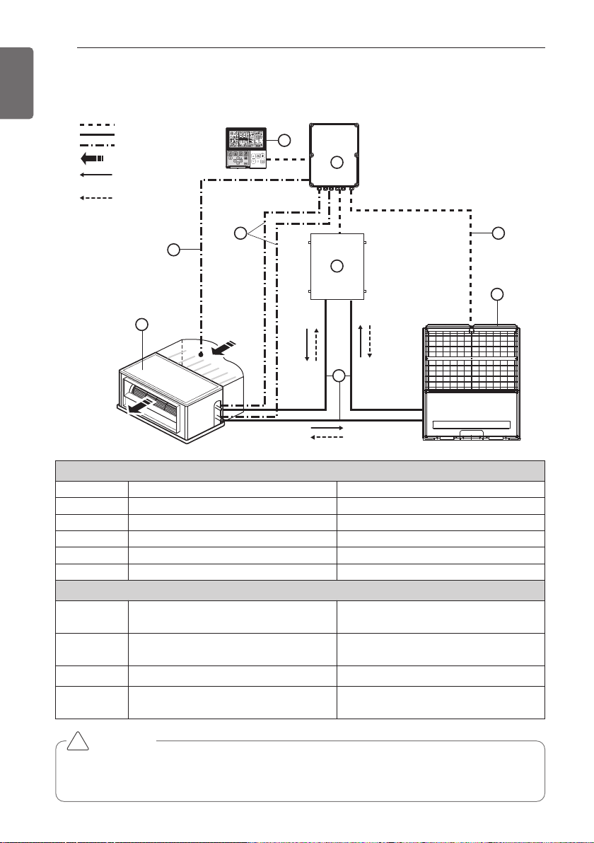
INSTALLATION SCENE
ENGLISH
Parts and components
No. Name Remarks
1 Air Handling Unit Field supply
2 Outdoor Unit Multi V
3 AHU Communication Kit(PRDCA0) 4 AHU EEV Kit(PRLK048A0/PRLK096A0) 5 Field piping Field supply
Wiring connections
6 Communication Kit Wiring
Power supply and communication
between comm. kit and outdoor unit
7
Pipe thermistors
(EBG61287703/EBG61287704)
Evaporator (In/Out) control of Air Han-
dling Unit
8 Room thermistor (EBG61106821) Return air control
9
Remote controller(PQRCVSL0
/ PQRCVSL0QW)
Optional accessory
CAUTION
For Installation of Room thermistor (No. 8), always place it at the inlet of Heat Exchanger.
Otherwise, it might not operate properly.
!
INSTALLATION SCENE
Signal
Pipe
Thermistor
Air flow
Refrigerant flow
(Cooling)
Refrigerant flow
(Heating)
8
1
9
3
7
4
5
6
2
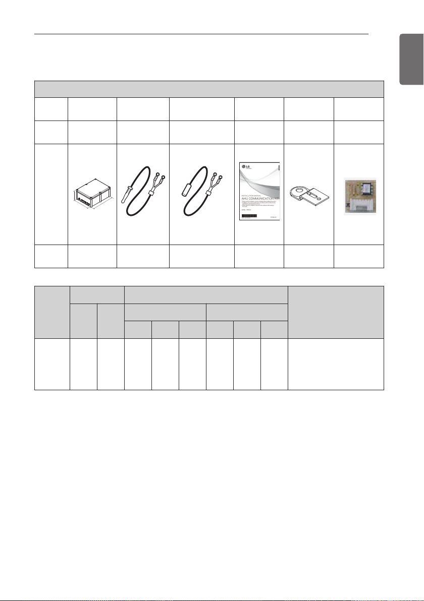
SUPPLIES
7
ENGLISH
PRDCA0
Compo-
nents
AHU Comm.
Kit
Room
thermistor
Pipe
thermistors
Installation
Manual
Bracket Option PCB
P/NO
AJT73857401 EBG61106821
EBG61287703(In)
EBG61287704(Out)
MFL50024804 MAZ49398901
EBR52358907
~17
Shape
Quanti-
ty(EA)
1 1 2(Each 1) 1 4 11(Each 1)
Model
Name
Weight (kg) Dimension (mm)
POWER
NET Gross
NET Gross
W H D W H D
PRDCA0 6.0 8.0 330 180 430 420 232 540
220-240 V~ 50 Hz
220 V~ 60 Hz
208/230 V~ 60 Hz
SUPPLIES
H
D
W
8
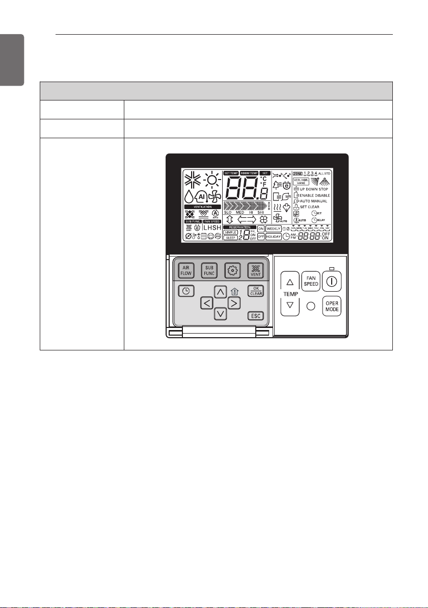
OPTIONAL ACCESSORIES
ENGLISH
* For further details of the accessories, refer to the manual provided at the time of purchasing
the accessories.
Accessories
Components Remote controller
Model name PQRCVSL0 / PQRCVSL0QW
Shape
OPTIONAL ACCESSORIES
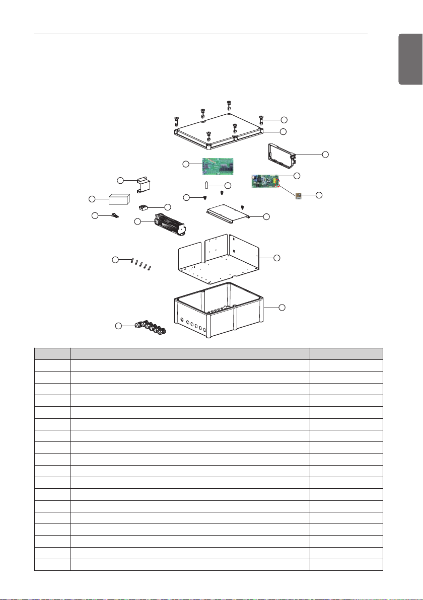
PART DESCRIPTION
9
ENGLISH
Communication Kit (PRDCA0)
No. m Part Name Quantity (EA)
1 Plastic (+) Bolt 6
2 Cover 1
3 Expansion I/O PCB 1
4 Supporter (Connect No. 3) 6
5 Main PCB case 1
6 Main PCB 1
7 Option PCB (192 kBtu/hr) 1
8 Bracket (For Adaptor) 1
9 AC/DC Convertor 1
10 Supporter (Fixing Wiring) 7
11 Terminal Block (Communication) 1
12 Terminal Block (POWER Supply) 1
13 Clamp Cord (For Power Wiring) 1
14 Clamp Cord 5
15 Panel 1
16 Control Box Case 1
17 Cable gland 6
18 Bracket (For Expansion I/O PCB) 1
PART DESCRIPTION
1
2
3
8
9
13
11
14
17
10
12
4
18
15
16
5
6
7
10
BEFORE INSTALLATION
ENGLISH
CAUTION
• Don't install or operate the unit in rooms mentioned below.
① Where mineral oil, like cutting oil is present.
② Where the air contains high levels of salt such as air near the ocean.
③ Where sulphurous gas is present such as that in areas of hot spring.
④ In vehicles or vessels.
⑤ Where voltage fluctuates a lot such as that in factories.
⑥ Where high concentration of vapor spray are present.
⑦ Where machines generating electromagnetic waves are present.
⑧ Where acidic or alkaline vapor is present.
⑨ The option boxes must be installed with entrances downward.
• Check the mentioned below, when you apply the AHU (Field supply).
① If the AHU (Field supply) provided in the field is exclusively for heating, you must not
change the operating mode to cooling on the remote controller. If not, it can cause
electric shock, injury or death. If you want to operate in cooling mode, AHU (Field supply) must comply with the following details.
(Following)
- The insulation level of AHU (Field supply) motor must be ‘F’ or above, and the protection level must satisfy ‘IP 54’.
- AHU (Field supply) must have the drain pan installed.
② Fan speed button on the wired remote controller (PQRCVSL0 /PQRCVSL0QW) is not
operated.
③ For refrigerant piping of outdoor unit, refer to the installation manual supplied with the
outdoor unit.
④ For installation of the wired remote controller (PQRCVSL0 /PQRCVSL0QW), refer to
the manual supplied with the wired remote controller.
⑤ For protecting the refrigerant cycle in heating, the inlet Air temperature to the Heat
Exchanger has to be over 5°C.
⑥ The EEV or TXV kit has to be installed on the AHU as close as possible to the Heat
Exchanger.
• AHU Communication Kit
① Thermistor cable and remote controller wire should be located at least 50mm away
from power supply wires and from wires to the controller. Not following this guideline
may result in malfunction due to electrical noise.
② Use only specified wires, and tightly connect wires to the terminals. Keep wiring in
neat order so that it does not obstruct other equipment. Incomplete connections could
result in overheating, and in worse case electric shock or fire.
!
BEFORE INSTALLATION
BEFORE INSTALLATION
11
ENGLISH
CAUTION
Selection of Evaporator(Air Handling Unit)
See table below for applicable units
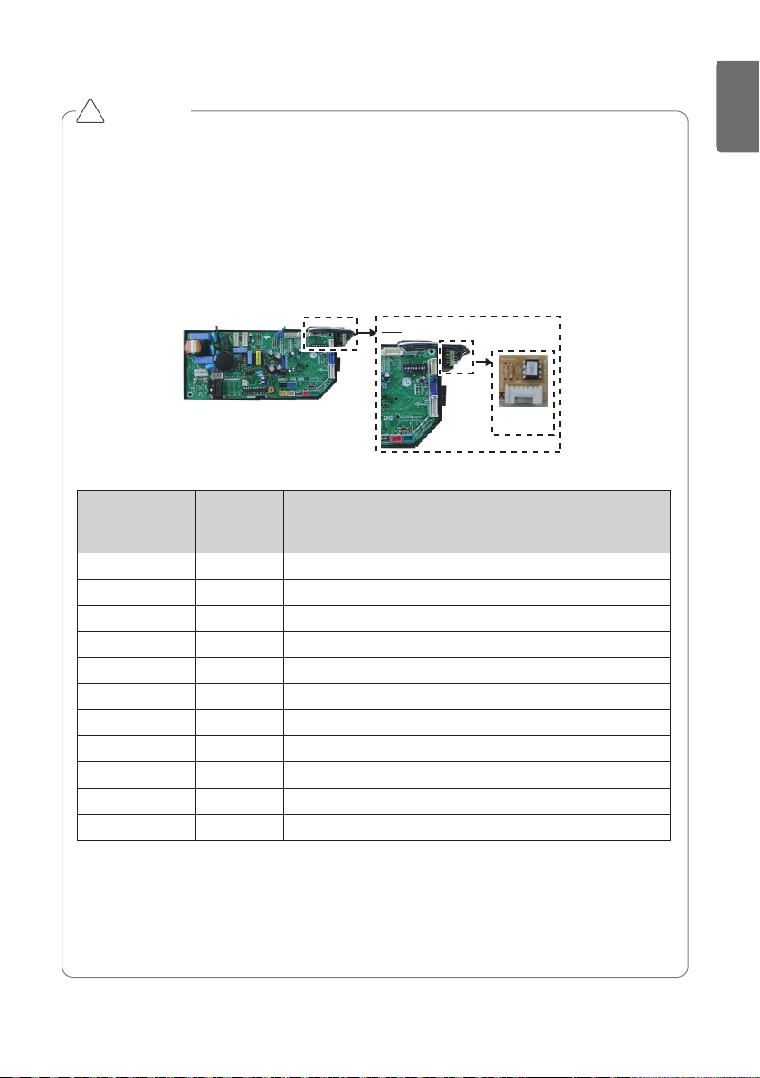
Selecting the capacity setting 'Option PCB'(Accessory) according to the capacity mentioned
below.
- The corresponding capacity setting 'Option PCB' needs to be selected depending on the
need capacity.
- After checking the need capacity, remove the 192 k Option PCB equipped in the main
PCB, and set up the Option PCB fitted the need capacity in the main PCB.
* Evaporator Saturated Temperature(SST) = 6 °C, SH (Superheat) 5K, Air Temperature =
27 °C DBT / 19 °C WBT
* Heat exchanger volume [m
3
] : Pipe cross-section × Tube length
-. Pipe cross-section [m
2
] = π × ID2/4
-. Tube length [m] = Tube length of 1 pipe × Tube step × Tube row
!
Option PCB
P/NO
Capacity
(Btu/h)
Standard heat
exchanger volume
(10-3× m3)
Maximum heat
exchanger capacity
(kW)
Air Flow rate
(CMM)
EBR52358907 28 k 2.7 8.6 22~26
EBR52358908 36 k 3.1 11 25~32
EBR52358909 42 k 3.4 13.8 31~35
EBR52358910 48 k 4.0 15.4 33~45
EBR52358911 76 k 5.4 22.2 50~64
EBR52358912 96 k 6.3 28.1 64~72
EBR52358914 115 k 7.3 33.7 72~88
EBR52358915 134 k 8.5 39.3 88~103
EBR52358916 153 k 9.5 45.4 103~116
EBR52358917 172 k 10.5 50.4 114~129
EBR52358913 192 k 11.2 56.2 121~137
Detail
Capacity setting
'Option PCB'

12
BEFORE INSTALLATION
ENGLISH
CAUTION
• AHU Operation range
- When installing Room thermistor, always place it to the inlet of Heat Exchanger. Otherwise, it may might not operate properly.
- Range of the inlet Air temperature to the Heat Exchanger is 18 ~ 40°C for cooling & 5 ~
30°C for heating. If the temperature is under 18°C for cooling & over 30°C for heating,
the system might operate ON and OFF because of protection logic system’s.
!
No Connection condition Combination
1
100% Fresh Air Intake
AHU only are connected
with outdoor units
1) The total capacity of 100% Fresh Air Intake AHU should be
50~100% of outdoor unit.

COMMUNICATION KIT INSTALLATION
13
ENGLISH
Mechanical installation
1 Remove the Comm. Kit box cover by unscrewing the plastic bolt (6EA)
2 Drill 4 holes on correct position and fix the Comm. Kit box securely with 4 screws
(Field supply) through the provided holes Ø4.5mm (Reference the length of the holes Ø4.5)
COMMUNICATION KIT INSTALLATION
Provided holes
Ø4.5 mm (4EA)
348 mm
332 mm

14
COMMUNICATION KIT INSTALLATION
ENGLISH
CAUTION
If you want to use Analogue Input signal for a variable capacity and a set temperature of
room, you have to connect the wiring of AI 10-2, AI 10-3, AI 10-4.
!
Circuit diagram
Electric Wiring Work

COMMUNICATION KIT INSTALLATION
15
ENGLISH
Terminal Block No. Connection Function Remark.
1(L) / 2(N) Power Supply
220-240 V~ 50 Hz
220 V~ 60 Hz
208/230 V~ 60 Hz
1-3 To AHU Fan Signal High/Mid/Low
4-9 To EEV Kit EEV Kit -
11-12 To AHU Communication Line Internet A, B
13-14
To Indoor Unit
Room Thermistor 15-16 Pipe In Thermistor 17-18 Pipe Out Thermistor 19-21 Remote Controller 23-24 To Outdoor Unit RS485 Communication -
25
Digital Input
DI 01-3 Operation ON/OFF
26 DI 01-1 Common Line
27 DI 23-3
Mode Change
28 DI 23-2
29 DI 23-1 Common Line
30 DI 45-3
Air Flow Rate
31 DI 45-2
33
Digital Output
DO 01-4 Running Status (ON/OFF)
34 DO 01-3 Common Line
35 DO 01-2 Comp. Status (ON/OFF)
36 DO 23-4
Running Mode
37 DO 23-2
38 DO 45-4
Air Flow Rate
39 DO 45-2
40 DO 67-4 Error Status
41 DO 67-1 Common Line
43
Analog Input
AI 10-2 Capacity Control
44 AI 10-3 Common Line
45 AI 10-4 Room Temperature Setting
CAUTION
If you want to use Analogue Input signal for a variable capacity and a set temperature of
room, you have to connect the wiring of AI 10-2, AI 10-3, AI 10-4.
!
Electric Wiring Work

16
COMMUNICATION KIT INSTALLATION
ENGLISH
1 For connection to outdoor unit and to controller (Field supply) :
Pull the wires inside through the cable gland and close the nut firmly in order to ensure a
good pull relieve and water protection.
2 The wires require an additional pull-relief. Strap the wire with the support tie wrap.
3 For the wired remote controller wire and outdoor unit communication wire, remove the
coating at the end of the wire to connect and use the ring type (Ø3) to connect to the terminal block.
t
Ring type (Ø3)
Connection of the wires
Electrical Work
Support
tie wrap
(Front View)
Detail
Nut of cable
gland
(Side view)
Cable Inser

COMMUNICATION KIT INSTALLATION
17
ENGLISH
CAUTION
• All field supplied parts and materials and electric works must be conform to local codes.
• Use copper wire only.
• All wiring must be performed by an authorized electrician.
• A main switch or other means for disconnection, having a contact separation in all poles,
must be incorporated in the fixed wiring in accordance to relevant local and national legislation.
• Refer to the installation manual attached to the outdoor unit for the size of power supply
electric wire connected to the outdoor unit, the capacity of the circuit breaker and switch,
wiring and wiring instructions.
!
Electric Wiring Work

18
COMMUNICATION KIT INSTALLATION
ENGLISH
CAUTION
- DI requires non-voltage contact
- DO provides relay output (max : 250Vac 1A)
- AI : 0Vdc ~ 10Vdc
- RS485 port : Connect to INTERNET A/B on ODU’s main PCB
!
ڸ
ڹ
ں
1 Analog Input : Actually only AHU controller controls or regulate SA temperature, we
only increase or decrease capacity of ODU and Comp. capacity of MULTI
_V.
2 Digital Input : Acquires the control value of AHU operation from DDC(Field supply).
3 Digital Output : Send the condition value of AHU operation to DDC (Field supply).
4 RS485 : Sends the On/Off signal taking from DDC to the indoor & outdoor unit and send the
condition value taking from indoor & outdoor unit to DDC with On/Off Output.
0
C
① Rotary S/W
Capacity controller
Controller Setting Method
Communication port
(1ch, RS485)
Reset
Button
Power(DC 12V)
Digital Input(5ch)
Analog Input(2ch)
Rotary S/W
(3EA)
Digital Output(7ch)
DIP S/W(SW03)
DIP S/W(SW01)
1
0
F
SW_GRP
3
2
E
D
SW_IO
4
C
SW_SPARE
This S/W is for setting up the address of
AHU Comm. Kit (00 ~ FF).
Example) AHU Comm. Kit address is ‘0C’ .
4
3
5
2
E
D
SW_GRP
6
7
8
9
A
B
C
1
0
F
SW_IO
5
6
7
8
9
A
B
SW_TYPE
This S/W is for setting up the
temperature from AHU Comm. Kit.
Detail information refer to the 20 page.

COMMUNICATION KIT INSTALLATION
19
ENGLISH
ྚ
② Dip S/W(SW03)
S/W
name
No
Item
On
Off
Note
SW03
_SW
1
RS485/IDU
RS485
Not available
-. RS485 : Connect to INTERNET A/B
on ODU unit
2 Master/Slave
Master
Slave
-. Master is default for single unit
installation
-. Master is only one among multiple
unit
3
Control enable /
disable
DI/DO
enable
DO only
enable
-. Enable : DI/DO are enable
-. Disable : DO only are enable
4
Room
Temperature
setting 1
AI
Rot.S/W
-. AI : Input as analog input
(Controlled through DDC)
-. Rot. S/W : manual setting
5
Air flow rate
High/Low
High/Mid/Low
-. On : Mid step is not available.
(Mid step is displayed as current
step)
6
Room
Temperature
setting 2
Default
AI / Rot. S/W
Room Temperature Default setting
-. On : Default(Cooling 18°C, Heating
30°C)
-. Off : Room air(or return air) temperature control using Al Signal and
Rotary S/W (Refer to the DIP S/W
No.4)
7
Not available
-
-
-
8
Flash Writing
Normal
On-boarding
-. Default : On
CAUTION
When the Dip S/W No. 6 is On, capacity control is possible and the value of Analogue input
signal for temperature control, Rotary S/W and Remote controller is ignored. In case of setting the temperature of room using Analogue input signal , Rotary S/W and Remote controller, Dip S/W No. 6 have to be Off certainly.
!
* Setting : Black
OFF
876 543 21
876 543 21
SW03_SW
[Default setting]
- . No 1/2/3/4/6/7/8 : On
- . No 5 : Off

20
COMMUNICATION KIT INSTALLATION
ENGLISH
ྛ
③ Dip S/W(SW01)
S/W name
No
Item
Setting Dip S/W
AI Function
1
2
3
SW01
_SW
1 ~3
ODU
Capacity
Option
Setting
Off Off Off Option #1
On Off Off Option #2
Off On Off Option #3
4~8 Not available - - - -
* Setting : Black
OFF
876 543 21
876 543 21
SW01_SW
[Default setting]
-. No 1/2/3/4/5/6/7/8 : Off

COMMUNICATION KIT INSTALLATION
21
ENGLISH
Rotary S/W
ڸ
ڹ
④ Room Temperature control from DDC or Rotary S/W
h
According to Dip S/W(SW03) Setting, you can set up the Function of Room Temperature control.
Dip S/W(② SW03)
Function
Setting
Dip S/W
No 1
ON RS485 Communication with MULTI V
OFF Not available
No 3
ON Possible to control Room Temperature Function (Default)
OFF Only Monitoring (DO Signal only is enable)
No 4
ON DDC Control (Wiring No. AI 10-4)
OFF Rotary S/W(SW_TYPE) Control
No 6
ON Room Temperature Default setting (Cooling 18°C, Heating 30°C)
OFF
Room Air(or return air) temperature control using Al signal and Rotary S/W
• Dip S/W(SW03) NO 4 : OFF
Rotary
S/W(①) Number
Room Temp.(°C) Cooling Room Temp.(°C) Heating
0 Not available Not available
1 18 16
2 18 17
3 18 18
4 19 19
5 20 20
6 21 21
7 22 22
8 23 23
9 24 24
A 25 25
B 26 26
C 27 27
D 28 28
E 29 29
F 30 30
ڹ
ڸ
Rotary S/W
Dip S/W(SW03)

22
COMMUNICATION KIT INSTALLATION
ENGLISH
• Dip S/W(SW03) NO 4 : ON
Example) 5.85~6.15 Voltage is recognized as 6.0V.
Analog Input 10-4 (VDC)
Room Temp.(°C)
Cooling
Room Temp.(°C)
Heating
Normal
Range
Min. Max.
0.5 0 1.15 Not available Not available
1.5 1.35 1.65 18 16
2 1.85 2.15 18 17
2.5 2.35 2.65 18 18
3 2.85 3.15 19 19
3.5 3.35 3.65 20 20
4 3.85 4.15 21 21
4.5 4.35 4.65 22 22
5 4.85 5.15 23 23
5.5 5.35 5.65 24 24
6 5.85 6.15 25 25
6.5 6.35 6.65 26 26
7 6.85 7.15 27 27
7.5 7.35 7.65 28 28
8 7.85 8.15 29 29
8.5 8.35 8.65 30 30
9.5 8.85 10 Not available Not available
CAUTION
If you want to control the Room Temperature using Remote controller, you have to be off
the Dip S/W 4 and Dip S/W 6, and setting the Rotary S/W to the ‘0’ .
!

AHU KIT WIRING CONFIGURATION WITH DDC
23
ENGLISH
AHU KIT WIRING CONFIGURATION WITH DDC
Configuration concept
1 Comm. Kit control capacity of the cooling/heating only according to the DDC’s control
signal (DC 0~10V)
2 Control signal from the DDC is decided by calculation logic with Td/Ti and setting tempera-
ture (Calculation logic depends on BMS program).
3 For Installation of Room thermistor, recommended to be installed to the inlet of Heat
Exchanger.
BMS
system
AHU
Comm. Kit
0~10V DC
(AI 10-2)
(Multi V)
0~10V DC
(AI 10-4)
DI/DO
Room
Temp. sensor
Target
pressure
Modulating
DDC
Discharge Temp. sensor
( DC 0~10V Output)
(AHU)
Ti : Inlet Temp.
Te : HEX. Temp.
Td : Discharge Temp.
TdTeTi
Field Su pp lyLG Supply

24
AHU KIT WIRING CONFIGURATION WITH DDC
ENGLISH
Wiring
No.
Input
Logic Conditions
Open Short
DI 01-3
Operation
Off
Operation
On
-. When short, the fan signal (FAN) is On
and ODU will start to run.
-. When open, ODU will off and FAN
changes to Off.
-. Operation mode
: DI 23-3/23-2
-. Fan mode
: DI 45-3/45-2
DI 23-3
FAN
Operation
Cooling or
Heating
-. When open, FAN is On but ODU will
not run.
-. When short, FAN is On and mode is
decided DI 23-2.
-. If no more cooling and heating is necessary, DI 23-3 is open and DI 01-3 is
On.
-. DI 01-3 : short
DI 23-2
Cooling
Operation
Heating
Operation
-. When open, mode is cooling
-. When short, mode is heating
-. DI 01-3 : short
-. DI 23-3 : short
DI 45-3
Low FAN
Mid FAN
-. When DI 45-3/45-2 are open : Low fan
mode and FAN is On.
-. When DI 45-3 is short : Mid fan and
FAN is On.
-. DI 01-3 : short
-. Operation mode
: DI 23-3/23-2
DI 45-2 High FAN
-. When DI 45-2 short : High fan and
FAN is On.
-. When DI 01-3 is open : FAN is Off, DI
45-3,/45-2 are neglected.
NOTE
!
Fan signal (FAN) can be delayed on heating mode start up despite of fan mode (DI 45-3/45-2)
because fan signal (FAN) will be On , if temperature of refrigerant pipe sensors (PIPE_IN,
PIPE_Out) are higher than 20°C to prevent cold air discharge.
DI Specification
: Non-Voltage Contact
DI Wring concept
Digital Input(5ch)

AHU KIT WIRING CONFIGURATION WITH DDC
25
ENGLISH
Digital Output(7ch)
NOTE
!
If AHU should have High/Mid/Low fan mode, Fan control in AHU should utilize DO 45-4 /45-2
(Non-Voltage Contact).
Wiring
No.
Output
Logic
Open Short
DO 01-4
OperationOnOperation
Off
-. When DI 01-3 is short, ODU and FAN are On.
-. When DI 01-3 is open, ODU and FAN are Off.
DO 01-2
Compressor
is Off
Compressor
is On
-. When ODU compressor is running, it is short.
-. When ODU compressor is off, it is open
DO 23-4
Cooling / Heating
Defrosting / FAN
-. When DO 23-4 / 23-2 are open, it is ventilation mode.
-. When DO 23-4 is open, DO 23-2 is short, it is defrosting
during heating. FAN can be OFF if PIPE_IN and
PIPE_OUT are less than 20°C.
-. When DO 23-4 is short, DO 23-2 is open, it is cooling.
-. When DO 23-4 is short, DO 23-2 is short, it is heating
-. Defrosting mode only works when it is connected with
ODU.
DO 23-2
DO 45-4
Low FAN
Mid FAN
-. When DO 45-4 / DO 45-2 are open, it is low fan mode.
-. When DO 45-4 is short and DO 45-2 is open , it is mid
fan mode.
DO 45-2 High FAN
-. When DO 45-2 is short, it is high fan mode (DO 45-4 is
neglected).
DO 67-4 No Error
Error
Occurred
-. When DO 67-4 is short, ODU has error and ODU stops
FAN is Off.
DO Specification
: AC 250V, DC 30V, 1A
DO Wring concept

26
AHU KIT WIRING CONFIGURATION WITH DDC
ENGLISH
Discharge Temperature Control through controlling of ODU capacity
AI Specification : DC 0~10V
AI
No.
Input
voltage
[Vdc]
Low
[Vdc]
High
[Vdc]
Capacity
of unit
[%]
Cooling
Heating
Control
Target
Low
Pressure
[kPa]
Tempera-
ture at
HEX [°C]
Target
High
Pressure
[kPa]
Tempera-
ture at
HEX [°C]
AI
10-2
0 0 0.4 No limit ----
DI should be
decided.
1 0.6 1.4 100 800 10.5 3,000 49.2
DI will determine
fan mode and
operation mode.
2 1.6 2.4 90 830 11.3 2,990 49.0
3 2.6 3.4 80 870 12.5 2,730 45.1
4 3.6 4.4 70 930 14 2,560 42.5
5 4.6 5.4 60 990 15.8 2,340 38.9
6 5.6 6.4 50 1,070 17.9 2,080 34.1
7 6.6 7.4 45 1,100 19 1,950 31.5
8 7.6 8.4 40 1,160 20.3 1,800 28.4
9 8.6 9.4
Comp.
off
----
If it is 9V, DO 01-4
is short, DO 01-2
is open.
10 9.6 10 All off ----
ODU and fan are
Off.
AI Wring concept
1. Option #1
Analog Input(2ch)
* Setting DIP S/W(SW01)
1.Option #1
OFF
876 543 21
876 543 21
2.Option #2
OFF
876 543 21
876 543 21
3.Option #3
OFF
876 543 21
876 543 21

AI
10-2
0 0 0.4
Comp.
off
---DO 01-4 is short,
DO 01-2 is open.
1 0.6 1.4
Comp.
off
----
2 1.6 2.4 40 1,160 20.3 1,800 28.4
DI will determine
fan mode and
opeation mode
3 2.6 3.4 45 1,100 19.0 1,950 31.5
4 3.6 4.4 50 1,070 17.9 2,080 34.1
5 4.6 5.4 60 990 15.8 2,340 38.9
6 5.6 6.4 70 930 14.0 2,560 42.5
7 6.6 7.4 80 870 12.5 2,730 45.1
8 7.6 8.4 90 830 11.3 2,990 49.0
9 8.6 9.4 100 800 10.5 3,000 49.2
10 9.6 10 100 800 10.5 3,000 49.2
AHU KIT WIRING CONFIGURATION WITH DDC
27
ENGLISH
AI
No.
Input
voltage
[Vdc]
Low
[Vdc]
High
[Vdc]
Capacity
of unit
[%]
Cooling
Heating
Control
Target
Low
Pressure
[kPa]
Tempera-
ture at
HEX [°C]
Target
High
Pressure
[kPa]
Tempera-
ture at
HEX [°C]
AI
No.
Input
voltage
[Vdc]
Low
[Vdc]
High
[Vdc]
Capacity
of unit
[%]
Cooling
Heating
Control
Target
Low
Pressure
[kPa]
Tempera-
ture at
HEX [°C]
Target
High
Pressure
[kPa]
Tempera-
ture at
HEX [°C]
2. Option #2
3. Option #3
AI
10-2
0 0 0.4
Comp.
off
----
DO 01-4 is short,
DO 01-2 is open.
1 0.6 1.4 40 1160 20.3 1800 28.4
DI will determine
fan mode and
opeation mode
2 1.6 2.4 45 1100 19.0 1950 31.5
3 2.6 3.4 50 1070 17.9 2080 34.1
4 3.6 4.4 60 990 15.8 2340 38.9
5 4.6 5.4 70 930 14.0 2560 42.5
6 5.6 6.4 80 870 12.5 2730 45.1
7 6.6 7.4 90 830 11.3 2990 49.0
8 7.6 8.4 100 800 10.5 3000 49.2
9 8.6 9.4 100 800 10.5 3000 49.2
10 9.6 10 100 800 10.5 3000 49.2

28
AHU KIT WIRING CONFIGURATION WITH DDC
ENGLISH
HEX
M
M
h If the motor is On/Off type, HI/MED/LOW wire have to connect as common.
For example, If you just connect HI wire to the motor(On/Off), motor is not operating according
to our control logic.
FAN Signal Wiring Concept
ſſ
1(L) 2(N)
ſſ
[AHU]
N
R-LOW
Motor
Relay
Field Wiring
Factory Wiring
[AHU Comm. Kit]
HI(L)
MED(L)
LOW(L)
LOW
MED
HI
R-HI R-MED
ƖƖ
12
ƖƖ
Ɩ
3
Ɩ
ƖƖ
1(L) 2(N)
ƖƖ
(MCC Panel )
Motor operating power
220-240 V~ 50 Hz
220 V~ 60 Hz
208/230 V~ 60 Hz
Control power
220-240 V~ 50 Hz
220 V~ 60 Hz
208/230 V~ 60 Hz
Cable : Over CV 1.5mm
2

THERMISTORS INSTALLATION
29
ENGLISH
Pipe thermistors Installation
Location of the pipe thermistors
A correct installation of the thermistors is required to ensure a good operation :
1 Pipe_In(EBG61287703)
: Install the thermistor behind the distributor on the coldest pass the heat exchanger
(contact your heat exchanger dealer).
2 Pipe_Out(EBG61287704)
: Install the thermistor at the outlet of the heat exchanger as close as possible to the heat
exchanger.
Evaluation must be done to check if the evaporator is protected against freeze-up.
Execute test operation and check for freeze-up.
1 Pipe_In(Suction pipe)
2 Pipe_Out(Discharge pipe)
(Air Handling Unit)
THERMISTORS INSTALLATION
1
2

30
THERMISTORS INSTALLATION
ENGLISH
Installation of the pipe thermistor cable
1 Put the thermistor cable in a separate protective tube.
2 Always add a pull-relief to the thermistor cable to avoid strain on the thermistor cable and
loosening of the thermistor. Strain on the thermistor cable or loosening of the thermistor may
result in bad contact and incorrect temperature measurement.
Fixation of the pipe thermistors (Field work)
1 Fix the thermistor with insulating aluminum tape (Field supply) in order to ensure a good heat
transfer.
2 Put the supplied piece of rubber around the thermistor (EBG61287703/04) in order to avoid
loosening of the thermistor after some years.
3 Fasten the thermistor with 2 tie wraps (Field Supply)
4 Insulate the thermistor with insulation sheet(Over 5t, Field Supply)
123 4
Tie wrap
1
45°
2
Thermistor

THERMISTORS INSTALLATION
31
ENGLISH
INSTRUCTION
!
• Put the thermistor wire slightly top to above water accumulation on down of the thermistor.
• For sensing the evaporator’s temp. in thermistor, Put the upper port the thermistors on the
evaporator, this is the most sensitive point of the thermistor.
1 Most sensitive point of the thermistor
2 Maximize the contact
Water
2
1
45 °

32
TROUBLESHOOTING
ENGLISH
[Error Code]
Display Number Error Item Cause of Error
CH 01 Room Temperature
Temperature sensor disconnection or
short circuit on Room or RA of AHU
CH 02
Pipe In Temperature sensor
error
Temperature sensor disconnection or
short circuit on pipe inlet of AHU
CH 03
Communication error between
wired remote controller and
Comm. Kit
No communication signal for more
than 3 minutes from wired remote
controller to the Comm. Kit
CH 05
Communication error between
Comm.
Kit and Outdoor Unit
No communication signal for 5 minutes
continuously from Comm. Kit to Outdoor Unit
CH 06
Pipe Out Temperature sensor
error
Temperature sensor disconnection or
short circuit on pipe outlet of AHU
CH 09 Option PCB EEPROM error
No reading signal for 5 times continuously from EEPROM to Comm. Kit
Problem Cause Remedy
AHU Communication Kit
does not work
No power supply
Check the electrical connection and voltage
of the power supply.
Wiring is wrong
Check the electrical connection of the
Communication Kit (Refer to the circuit diagram of the Communication Kit)
AHU Communication Kit
is broken
Check the electrical and mechanical part.
TROUBLESHOOTING

33
ENGLISH

34
ENGLISH

 Loading...