

Page 1

LG
AHU CONTROL KIT
Owner's Manual
LG
IMPORTANT
• Please read this installation manual completely
before installing the product.
• Installation work must be performed in
accordance with the national wiring standards
by authorized personnel only.
• Please retain this installation manual for future
reference after reading it thoroughly.
Visit us at : http://www.lgservice.com
Models: PRCKD20E
PRCKD40E
ENGLISH ITALIANO ESPAÑOL FRANÇAIS
PORTUGUESE
Page 2

2 AHU CONTROL KIT
AHU CONTROL KIT Owner's Manual
TABLE OF CONTENTS
■ Safety Precautions...............................................................3
■ Necessary sensor by operating mode ................................6
■ Part Description ...................................................................7
■ Basic operation of wired remote controller..........................8
■ Main function of wired remote controller.............................9
■ Supplementary function of wired remote controller..........11
■ Humidifier........................................................................................11
■ Desired humidity control .................................................................12
■ Auto ventilaton ................................................................................13
■ Desired CO
2 level control ................................................................14
■ Reservation function of wired remote controller ...............15
■ Changing Current Time .................................................................15
■ Programming : Setting Simple Reservation..................................17
■ Programming : Setting ON Reservation........................................18
■ Programming : Setting OFF Reservation......................................19
■ Programming : Weekly Reservation..............................................20
■ Programming : Holiday Reservation..............................................22
■ Setting function of wired remote controller installation .....23
■ How to start installation setting mode ...........................................23
■ Setting function by code ................................................................24
■ Central control address setting......................................................25
■ Damper opening setting ................................................................26
■ Remote control Master/Slave setting ............................................28
■ Manual operating mode.....................................................29
■ SA fan operation ............................................................................29
■ RA fan operation............................................................................29
■ Check before requesting for service .................................30
■ Test run ..............................................................................31
■ Self diagnosis function...................................................................31
Page 3
Safety Precautions
Owner's Manual 3
ENGLISH
■ Installation
Safety Precautions
To prevent injury to the user or other people and property damage, the following instructions must be followed.
■ Incorrect operation due to ignoring instruction will cause harm or damage. The seriousness is
classified by the following indications.
■ Meanings of symbols used in this manual are as shown below.
This symbol indicates the possibility of death or serious injury.
This symbol indicates the possibility of injury or damage.
Be sure not to do.
Be sure to follow the instruction.
WARNING
Always ground the product.
• If the product is not grounded
properly, it can cause an
electric shock.
When installing the product,
always install the electric
circuit breaker and the
exclusive switch.
• If they are not installed, it can
cause a fire or an electric
shock.
Do not use damaged circuit
breaker or exclusive switch.
• It can cause a fire or an
electric shock.
Do not store or use
flammable gas or volatile
substance near the air
conditioner.
• It can cause a fire or problem
to the product.
Do not bend or damage the
power cable.
• It can cause a fire or an
electric shock.
For the electric
construction, request for
service to the distributor or
the service center.
•
Arbitrary disassembly or repair
can cause a fire or an electric
shock.
System air conditioner can
only be installed by
specialized service provider
with air condition
installation certifications.
• Inappropriate installation can
cause leakage, fire and
electric shock.
When moving or reinstalling
the air conditioner, please
contact the
MULTI VTM AHU
installation service provider.
• Inappropriate installation can
cause leakage, fire and
electric shock.
Do not disassemble, repair
or reconfigure the product
arbitrarily.
• It can cause a fire and electric
shock.
WARNING
CAUTION
Page 4
Safety Precautions
4 AHU CONTROL KIT
The electric construction
must be performed by an
electrician for electric
installation based on the
installation manual and
designated circuit diagram.
• Use of inappropriate wire and
electric construction, can
result in an electric shock or
a fire. Technical standard for
electric equipment
Use designated installation
material at the designated
location for the product
installation.
Do not install the product
outdoors.
When opening the box or
installing the product, be
careful of any sharp objects.
• It can cause an injury.
Use the fuse of rated
capacity.
• It can cause a fire or an
electric shock.
For the product installation,
request for service to the
service center or the
installation service provider.
•
It can cause a fire , an electric
shock, an explosion or an injury.
■ Operation
Do not let water get inside
(Controller) the product.
Especially do not wash the
product with water.
• It can cause an electric shock
or a problem to the product.
Do not leave the product
near a heating device.
• It can cause a fire.
Do not change or expend
the power cord arbitrarily.
• It can cause a fire or an
electric shock.
Use exclusive cable for the
product.
• It can cause a fire or an
electric shock.
If you hear or smell a weird sound
or odor, or if you see smoke from
the product or if you experience a
power outage, pull down the main
power switch.
• If not, it can cause a fire or an
electric shock.
Do not put any heavy
objects on top of the power
cable.
• It can cause a fire or an
electric shock.
Do not let the work or the
user get on top of the
product.
• He or she can fall over to get
injured.
Do not use any heating devices
near the power cable.
• It can cause a fire or an
electric shock.
Do not turn off the power
with the main power switch
while the product is
operating.
• It can cause a fire or an
electric shock.
Do not operate the switch
with wet hands.
• It can cause a fire or an
electric shock.
If you are not planning to use the
product for a long period of time,
pull down the main power switch.
• It can cause a fire or an
electric shock.
If the gas leaks, open the
window to ventilate the
room before operating the
product.
• It can cause an explosion or
a fire.
Page 5
Safety Precautions
Owner's Manual 5
ENGLISH
When installing the product,
make sure to level the
product.
• It can cause vibration or
leakage.
Do not install the product at
a location where flammable
gas is leaking.
• It can cause a fire or a
problem to the product.
Do not carry the product by
yourself.
• You can get injured by doing
so.
■ Operation
CAUTION
Do not put containers with water on top of the product.
• If the water spills over, it can cause a fire or an electric shock.
Page 6
6 AHU CONTROL KIT
Necessary sensor by operating mode
Operating mode Necessary sensor Function
SA temperature sensor
RA temperature sensor
- This runs indoor air conditioning.
-
Initial external air inlet setting is 30% of the air
supply during the air conditioning and this can be
changed by the user. But, when the damper actuator
is installed on AHU, the setting can be changed.
- This runs the indoor heating.
-
Initial external air inlet setting is 30% of the air
supply during the heating and this can be changed
by the user. But, when the damper actuator is
installed on AHU, the setting can be changed.
-
This is the operating function to run indoor air
conditioning by controlling multiple outdoor units by
comparing the enthalpy of the indoor/outdoor air.
-
During the power save operation, the operation switches
between partial air conditioning operation (Controlling
multiple outdoor units) and external air conditioning
operation (Outdoor unit OFF, 100% external air flow).
-
This is operating function is mainly used in between
seasons. But if there is no OA temperature/humidity
sensor and RA temperature/humidity sensor on the
AHU, the power save operation cannot be selected.
-
This is the operating function to remove the indoor
humidity when the humidity level indoor is excessive.
-
During the dehumidifier operation, the set value is
50%RH and the user cannot change this setting. But
if there is no OA temperature/humidity sensor and
RA temperature/humidity sensor on the AHU, the
dehumidifier operation cannot be selected.
-
This is the operating function to control the humidity to
the set value by detecting the indoor humidity level.
- This can be selected during heating operation.
But if there is no humidifier/humidifying valve and
RA temperature/humidity sensor on the AHU, the
humidifier operation cannot be selected.
- When the mixing temperature during the heating
operation is below the set value (5°C),
preheating device automatically operates. The
preheating device and mixing temperature
sensor must be installed on AHU for this to
operate automatically.
-
This is the operating function to control the amount of
external air flow so that the CO2 level is controlled
within the set level by detecting the indoor CO2 level.
- The initial CO2 level is set to 1000ppm, and can
be changed by the user.
-
This function operates when auto ventilator
(Additional operation) is selected during air
conditioning or heating operation. But if there is no
CO2 sensor and damper actuator on the AHU, the
auto ventilator operation cannot be selected.
SA temperature sensor
RA temperature sensor
SA temperature sensor
RA temperature sensor
SA temperature sensor
RA temperature sensor
Mixing temperature/
humidity sensor
SA temperature sensor
RA temperature sensor
CO
2 sensor
Damper actuator
SA temperature sensor
RA temperature sensor
OA temperature/
humidity sensor
SA temperature sensor
RA temperature sensor
OA temperature/
humidity sensor
Damper actuator
Air conditioning
Heating
Power save
Dehumidify
Humidification
Auto ventilation
Preheating
Necessary sensor by operating mode
Page 7
Owner's Manual 7
ENGLISH
Part Description
Part Description
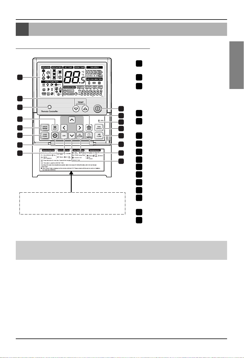
Name and Function of Remote Contr
oller
OPERATION INDICATION
SCREEN
SET TEMPERATURE Button
WIRELESS REMOTE
CONTROLLER RECEIVER
• Some products don't receive the
wireless signals.
VENTILATION Button
OPERATION MODE SELECTION
Button
SUBFUNCTION Button
FUNCTION SETTING Button
EXIT Button
ON/ OFF Button
ROOM TEMPERATURE Button
RESET Button
FAN SPEED Button
AIR FLOW Button
RESERVATION/ TIME SETTING
Button
SETTING/ CANCEL Button
UP, DOWN, LEFT, RIGHT Button
1
9
12
11
13
3
5
6
2
4
10
14
15
7
8
16
Please attach the inform label inside of the door.
Please choose proper language defend on your
country.
1
2
3
4
5
6
7
8
9
10
11
12
13
14
15
16
• 3/4/12/13 does not work.
• 6 Additional operation button depends on the application of the sensor.
Page 8
8 AHU CONTROL KIT
Basic operation of wired remote controller
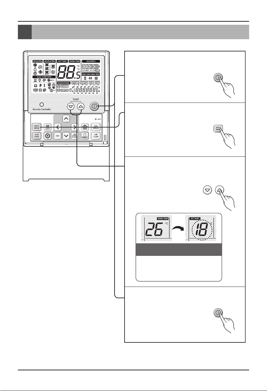
Press the Run/Stop button on the control
part of the remote controller to start the
operation.
1
Press the Operation Selection button to
set the operating mode (Heating/Cooling
etc.).
2
Press the Temperature Control button to
set the desired temperature below the
indoor temperature. (Based on air
conditioning operation)
3
When you press the Run/Stop button
during use, the operation will stop.
4
(Example) Remote controller
display window
▲ Indoor
temperature
▲ Desired
temperature
During the initial operation, the
desired temperature is
automatically set below the indoor
temperature.
Basic operation of wired remote controller
Page 9
Main function of wired remote controller
Owner's Manual 9
ENGLISH
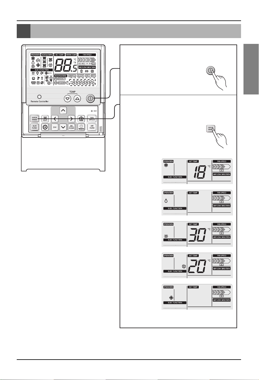
Every time you press the Run/Stop
button, the ON and OFF will be
repeated.
1
Every time you press the Operation Selection
button, it will change in the order of Air
Conditioner →Dehumidifier →Heater →
Power Save →Fan.
There are operating modes
that cannot be set depending
on the applied sensor.
2
<Air Conditioner>
<Dehumidifier>
<Heater>
<Power Save>
<Fan>
Main function of wired remote controller
Page 10
Main function of wired remote controller
10 AHU CONTROL KIT
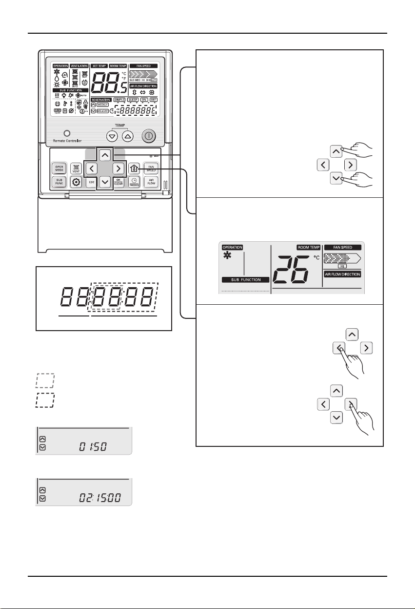
Every time you press the Temperature
Control button and the Up/Down button,
the desired temperature will change.
Air Conditioner/Power Save:
18~30°C / Heater: 16~30°C
Dehumidifier/Fan:
Desired temperature cannot be changed
3
When you press the Indoor Temperature
button, the Return Temperature of AHU will
be displayed for about 5 seconds.
4
To check the current humidity, press the ‘Left’
button when the indoor
temperature is displayed and
the indoor humidity will be
displayed at Display ‘C’.
To check the current CO2 level,
press the ‘Right’ button when
the indoor temperature is
displayed and the current
CO2 level will be
displayed at Display ‘C’.
5
Current humidity / CO2 level
(Function set by code)
* Code 01: Current humidity
* Code 02: Current CO
2 level
: Current humidity
: Current CO
2 level
Function
Code
Setting
(Example)
<Current humidity: 50%>
<Current CO2 level: 1500ppm>
Page 11
Owner's Manual 11
ENGLISH
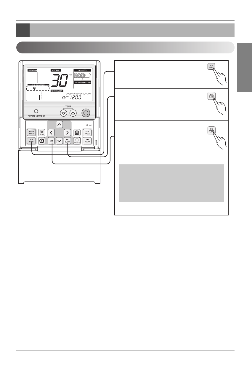
Supplementary function of wired remote controller
* Humidifier can only be set during heating
operation.
* Humidifier operation can only be used when the
humidifier is installed.
* The humidifier operation is controlled by the
desired temperature set.
Supplementary function of wired remote controller
Humidifier
B
Press the Additional Operation
1
button.
When the Humidifier icon
2
flashes in Display ‘B’, press the
Set/Cancel button to start the
humidifier.
When you press the OK/CLEAR
3
button one more time, the
humidifier will stop.
Page 12

12 AHU CONTROL KIT
Supplementary function of wired remote controller
Desired humidity control
* Desired humidity can be controlled in the range
of 40~60% by 5% increment.
* Default humidity is set to 50%.
Press the Function Setting
1
button.
Set the Function Code of
2
Display ‘C’ to 01.
C
Press the Up/Down button to set
3
the target humidity.
Press the OK/CLEAR button to
4
decide the desired humidity.
Display C: Desired humidity
Function
Code
(Function set by code)
* Code 01: Current humidity
: Desired humidity
(Example)
<Current humidity: 50%>
Setting
Page 13

Owner's Manual 13
ENGLISH
Supplementary function of wired remote controller
Auto ventilaton
* Auto Ventilator function can only be set during
the Air Conditioning/Heating operation.
Press the Additional Operation
1
button.
A
When the Auto icon flashes in
2
Display ‘A’, press the OK/CLEAR
button to start the Auto Ventilator.
When you press the OK/CLEAR
3
button one more time, the Auto
Ventilator will be canceled and
return to the previous operating
condition.
Page 14

14 AHU CONTROL KIT
Supplementary function of wired remote controller
Desired CO2level control
* Desired CO2 level can be controlled in the range
of 500~1500ppm by 100ppm increment.
* Default humidity is set to 1000ppm.
Press the Additional Operation
1
button.
Set the Function Code of
2
C
Display ‘C’ to 02.
Press the Up/Down button to set
3
the target CO
Press the OK/CLEAR button to
4
set the target CO
2 level.
2 level.
Display C: CO2 level
Function
Code
(Function set by code)
* Code 02: Desired CO
: Desired CO
(Example)
<Desired CO2 level: 500ppm>
Setting
2 level
2 level
Page 15

Owner's Manual 15
ENGLISH
Reservation function of wired remote controller
Reservation function of wired remote controller
Changing Current Time
Keep pressing button for 4
1
secs to enter Setting current
time mode.
Ex) Changing Current Time as
'Monday / AM 10:20'.
Press key to adjust the current
2
day.
Press key to move to AM/ PM setting
3
mode (the 'AM/ PM segment will flash).
Setting AM/ PM value by
4
pressing button.
Press button to move to 'Hour'
5
setting mode. (the 'Hour' segment will
flash)
Setting Hour value by pressing
6
button.
Page 16

16 AHU CONTROL KIT
Reservation function of wired remote controller
7
8
9
10
Press button to move to 'Minute'
setting mode. (the 'Minute' segment will
flash)
Setting Minute value by pressing
button.
Press button to finish.
In the process, press
button to release and exit
from setting mode.
(In case of exit with
incomplete information, it will
return to the previous setting )
Page 17

Owner's Manual 17
ENGLISH
Reservation function of wired remote controller
Programming : Setting Simple Reservation
In case of there is not any reservation setup on system, it is possible to make a SIMPLE reservation
on indoor unit.
❊ If the indoor is ON, we can make the reservation for turning OFF. In reserve, if the indoor is OFF,
we can set the timer for turning ON. The reservation time is from 1 to 7 hours.
Press button to enter the
1
Programming mode.
(the segment flashing)
Ex) Setting Simple Reservation
time as '3'.
Press button to adjust
2
reservation time.
Press button to finish setting.
3
Adjusting the reservation time after finish
4
reservation setting will release the
previous one.
Page 18

18 AHU CONTROL KIT
Reservation function of wired remote controller
Programming : Setting ON Reservation
This function is able to turn air conditioner ON after a setting time.
Press button.
1
Ex) Setting ON Reservation
Time as 'AM 10:20'.
Repeat pressing button to
2
enter the ON reservation
setting mode.
( segment flashing)
Press button to adjust AM/ PM
3
setting.
Press button to Hour setting
4
mode. When the Hour icon flash, please
setting time.
The setting range is within 1~12.
Press button to shift to Minute
5
setting mode. When the Minute icon
flash, please setting minute the setting
range is within 00~59.
Press button to finish setting.
6
Page 19

Owner's Manual 19
ENGLISH
Reservation function of wired remote controller
Programming : Setting OFF Reservation
This function is able to turn air conditioner OFF after a setting time.
Press button.
1
Ex) Setting OFF Reservation
Time as 'AM 10:20'.
Repeat pressing button to
2
enter the OFF reservation
setting mode.
( segment flashing)
Press button to adjust AM/ PM
3
setting.
Press button to shift to Hour
4
setting mode. When the Hour icon flash,
please setting time.
The setting range is within 1~12.
Press button to shift to Minute
5
setting mode. When the Minute icon
flash, please setting minute the setting
range is within 00~59.
Press button to finish setting.
6
Page 20

20 AHU CONTROL KIT
Reservation function of wired remote controller
Programming : Weekly Reservation
The weekly reservation is active after setting current time
Press programming button to enter
1
the Programming mode. Repeat
pressing button to select [Weekly
reservation].
(The segment will be flashed)
Ex) Setting one action as below.
- Day : TUE
- ON Time : 11:30 AM
- OFF Time : 12:30 PM
Press left, right button to adjust the
2
current day.
Press up, down button to adjust the
3
action number.
Press right button to move to 'Hour'
4
Part on ON Time section.
(The 'Hour' segment will be flashed)
Press up, down button to adjust the
5
Hour on Start Time section.
Press right button to move to
6
'Minute' Part on Start time section.
(The 'Minute' segment will be
flashed)
Start Time Section
Page 21

Owner's Manual 21
ENGLISH
Reservation function of wired remote controller
Press up, down button to adjust the
Minute on Start Time section.
7
Press right button to move to 'Hour'
Part on OFF Time section.
(The 'Hour' segment will be flashed)
8
Please refer the process from No.5
to No.7 for setting OFF Time. It is
same method.
9
If you finish the setting, press
setting/cancel button to complete
programming.
The under bar segment will be
created, when it finished.
10
Please refer the process from
No.2 to No.10 for setting other
day weekly program. It is same
method.
11
Press exit button to exit or system will
automatically release without any input after
25 seconds.
12
Off Time Section
Description of weekly reservation
<Start Time Section> <Off Time Section>
<Note>
Action
Start Time
Front
❋ Two actions per weekday can be programmed, in total 14 actions
To
Off Time
Page 22

22 AHU CONTROL KIT
Reservation function of wired remote controller
Programming : Holiday Reservation
This function is to automatically stop the machine working on some days.
Press button to enter the
1
reservation setting mode.
Repeat pressing button to
2
enter the holiday reservation
setting mode.
( segment flashing)
Press button to move to
3
holiday position.
Press button to set or
4
release a selected day as
holiday or not.
(❊ the holiday is indicated
with a underline)
If there is any holiday from
5
Monday to Sunday,
segment on LCD will be
displayed.
Press the button to exit or if
6
there is not any input, system
will release any setting after 10
seconds.
It is possible to set the air conditioner
7
OFF in every "holiday"
( ex. 9:00, 10:00, 13:00 )
Page 23

Owner's Manual 23
ENGLISH
Setting function of wired remote controller installation
How to start installation setting mode
Setting function of wired remote controller installation
Press the Function Setting button for
1
more than 3 seconds and the Code will
be displayed on Display ‘C’ to enter the
installation mode.
C
When you now press the Function
2
Setting button, the function code will
change.
Press the Up/Down button to change the
3
setting.
Press the Left/Right button to navigate
4
through the items.
Press the Set/Cancel button to complete
5
the setting.
Page 24

24 AHU CONTROL KIT
Setting function of wired remote controller installation
Setting function by code
Code 10: Test run (AHU has no function)
Code 11: Central control address setting
Code 12: Damper opening setting
Code 13: Remote controller
Master/Slave setting
Display C: Installation setting display
Function
Code
Setting1 Setting2
Page 25

Setting function of wired remote controller installation
Owner's Manual 25
ENGLISH
Central control address setting
* This is the function to set the central control
address of AHU.
Enter the Installation Setting mode.
1
Press the Function Setting button
2
repeatedly to reach function
code of ‘11’.
Press the Right button to
3
move to ‘Setting of 1’.
Press the Up/Down button
4
to set the central control
address.
Flashes
Flashes
Central
control
address
Press the Set/Cancel button
5
to complete the central
control address setting.
Display C: Installation setting display
Function
Code
Setting1 Setting2
Page 26

26 AHU CONTROL KIT
Setting function of wired remote controller installation
Damper opening setting
Enter the Installation Setting mode.
1
C
Repeatedly press the Function Setting
2
button to reach function code of ‘12’.
Press the Right button
3
to move to ‘Setting of 1’.
Press the Up/Down button to set the value.
4
‘Setting of 1’ for each mode is as follows.
* Cooling mode [ ‘01’ (OA) /‘02’ (EA) / ‘03’
(Mixing)]
* Heating mode [ ‘04’ (OA) /
‘05’ (EA) / ‘06’ (Mixing)]
* Fan mode [ ‘07’ (OA) /
‘08’ (EA) / ‘09’ (Mixing)]
Cooling
OA damper
Heating OA
damper
Flashes
Flashes
Fan OA damper
Display C: Installation setting display
Function
Code
Setting1
Setting2
Page 27

Owner's Manual 27
ENGLISH
Setting function of wired remote controller installation
* This is the function to set the damper opening
of AHU.
* This applies only to the site where the damper
actuator is installed.
Press the Right button to move to
5
‘Setting of 2’ by each mode.
Flashes
C
Press the Up/Down button to select the
6
damper opening.
The damper opening that can be set is
in the range of 1~91
degrees.
Air conditioning
external damper
opening of 40°
Heating external
damper opening
of 40°
Fan external
damper opening
of 40°
Press the OK/CLEAR button to complete
7
the setting.
Display C: Installation setting display
Function
Code
Setting1
Setting2
Page 28

28 AHU CONTROL KIT
Setting function of wired remote controller installation
Remote control Master/Slave setting
* This is the function to set the mainly
used remote controller.
* You can set one remote controller as
the Master and the rest as Slave.
Enter the Installation Setting mode.
1
C
Press the Function Setting button
2
repeatedly to reach function code of ‘13’.
Flashes
Press the Right button to move to
3
‘Setting of 1’.
Flashes
Press the Up/Down button to set the value.
4
Setting value of ‘01’ is
the Master and ‘00’
is the Slave.
Master
Slave
Press the OK/CLEAR button to
5
complete the setting.
Display C: Installation setting display
Function
Code
Setting1 Setting2
Page 29

Owner's Manual 29
ENGLISH
Manual operating mode
* The SA switch of the control kit during AHU
operation with the wired remote controller
must be maintained at OFF condition.
* The RA switch of the control kit during AHU
operation with the wired remote controller
must be maintained at OFF condition.
Manual operating mode
SA fan operation
RA fan operation
(Operating LED)
(Selector switch)
When you set the SA Fan Switch to ON,
1
4
5
3
2
1
the SA fan will operate manually.
SA fan operating LED will be turned on.
2
When you set the SA Fan Switch to OFF,
3
the SA fan will stop operating and can
be operated automatically with the wired
remote controller.
When you set the RA Fan Switch to ON,
1
the RA fan will operate manually.
RA fan operating LED
1
SA fan operating LED
2
Wired remote controller
3
SA fan switch
4
RA fan switch
5
RA fan operating LED will be turned on.
2
When you set the RA Fan Switch to
3
OFF, the RA fan will stop operating and
can be operated automatically with the
wired remote controller.
Page 30

Check before requesting for service
30 AHU CONTROL KIT
Check before requesting for service
When there is a problem with the product, check the following detail before requesting for service to
the service center.
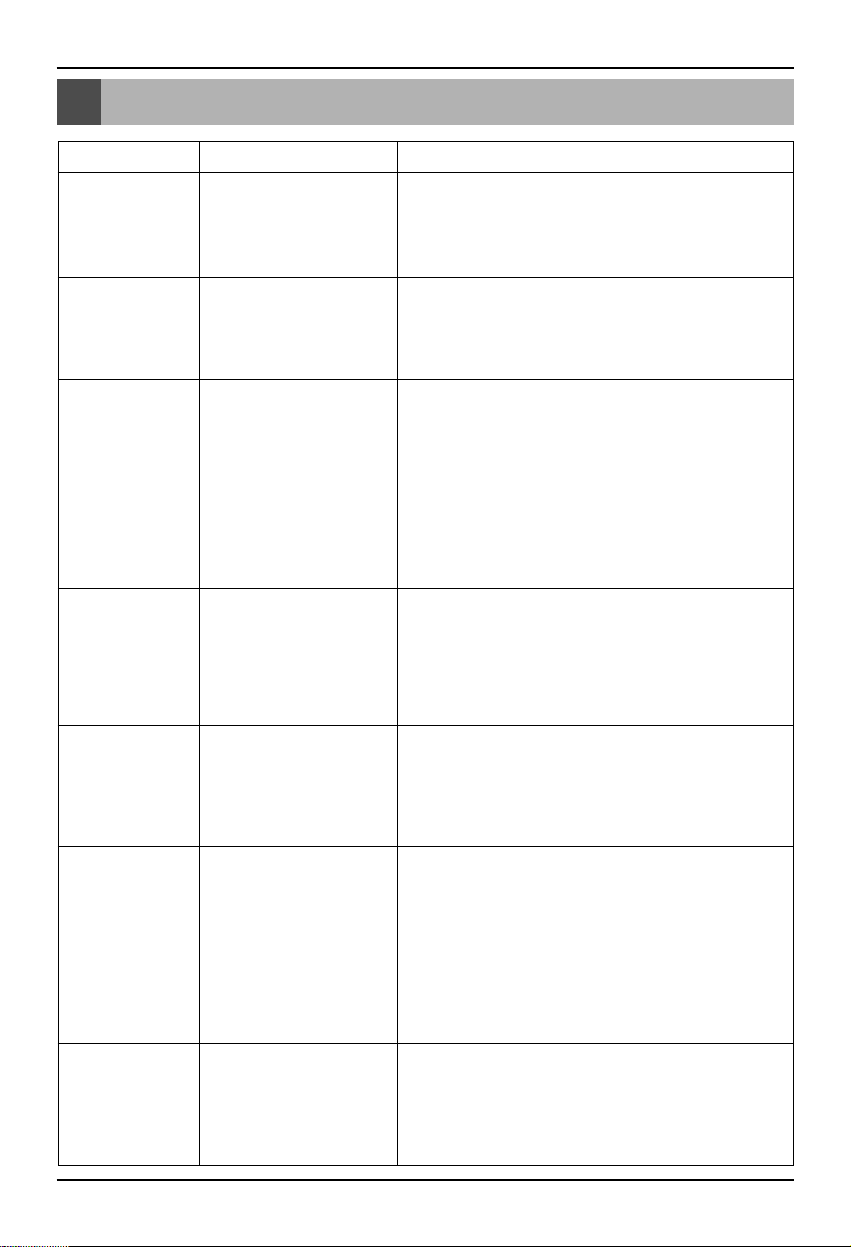
Symptom Check Action
The product does
not work at all.
The cool air does not
flow continuously.
I cannot set the
scheduled operation.
AHU automatically
goes off.
* Is the main switch turned off?
* Is there a power outage?
* The fuse inside the product
can be disconnected.
* Is the desired temperature set
higher than the indoor
temperature?
* Is the product running in
Dehumidifier/Power save
mode?
* Is the schedule properly set?
* Did you check the current
time?
* Is the OFF schedule set?
* Turn on the main power switch.
* Check the other electric appliances.
(If the power works, try operating the product again.)
* Request for service to the installation service provider or
the service center.
* Set the desired temperature to be lower than the indoor
temperature.
* Change the operating mode to air conditioning.
* Refer to the manual and try setting up the schedule again.
* If the current time is incorrect, try setting again.
* Check the remote controller and cancel the OFF schedule.
Page 31

Owner's Manual 31
ENGLISH
Test run
Test run
Self diagnosis function
Error display
Error display method
■ This function displays the self diagnosis and the type of error if identified.
■ For the error display, the applicable code is displayed on the 7 segment LED on the wired remote
controller and AHU controller.
■ If there are 2 or more errors simultaneously, the codes are displayed in the order of occurrence.
■ Once you resolve the error, the error code will disappear.
■ The first display on the 7 segment display refers to the error code and the second part refers to the
location information of the communication PCB address or sensor location. Refer to the following for
details.
* The address the communication PCB refers to the rotary switch number on the communication PCB.
* The above table shows the information of the attached location by sensor.
Error type Display condition Example of output Detail description
Basic error CH [Error code] 0 CH30 Error #3
Communication PCB error CH [Error code] [Address] CH204 Error #2 in communication PCB with
address of ‘#4’
Sensor error CH [Error code] [Location] CH1302 Air supply temperature sensor error
Outdoor unit error CH [Error code] [Address] CH17304
Error #173 on the outdoor unit connected
to communication PCB with address of
‘#4’
Location number Location name Applicable sensor type
01 RA Temperature sensor, humidity sensor
02 SA Temperature sensor, humidity sensor
03 OA Temperature sensor, humidity sensor
04 Mixing Temperature sensor
05 Differential pressure Differential pressure sensor
06 Static pressure Static pressure sensor
Page 32

32 AHU CONTROL KIT
Test run
Error display (AHU)
■ ‘##’ refers to the address information of the communication PCB.
Display
number
Error item Cause of error Cause or error
CH 2 ##
CH 3 00
CH 4 ##
CH 5 ##
CH 6 ##
CH 8 00
CH 13 01
02
04
CH 14 01
02
03
CH 15 00
CH 16 05
06
CH 17 01
02
Temperature sensor
error at pipe inlet of
indoor unit
Communication error
between wired remote
controller and AHU
controller
Communication error
between AHU
controller and
communication PCB
Communication error
between
communication PCB
and outdoor unit
Temperature sensor
error on pipe outlet of
indoor unit
Emergency operation
Temperature sensor
error
Humidity sensor error
CO2 sensor error
Pressure sensor error
Air flow sensor error
Communication PCB
rotary switch number
##
-
Communication PCB
rotary switch number
##
Communication PCB
rotary switch number
##
Communication PCB
rotary switch number
##
-
RA
SA
Mixing
RA
SA
OA
-
Differential pressure
Static pressure
RA
SA
Temperature sensor disconnection or short circuit at pipe inlet
of indoor unit
No communication signal for more than 3 minutes from wired
remote controller to the AHU controller
No communication signal for more than 3 minutes from
communication PCB to AHU controller
No communication signal for 5 minutes continuously from
communication PCB to outdoor unit
Temperature sensor disconnection or short circuit on pipe
outlet of indoor unit
The operating status of the smoke control mode through smoke detector is displayed
Temperature sensor (RA/SA/Mixing) disconnection/short
circuit/misconnection or when the sensor value is in the error
range
Humidity sensor (RA/SA/OA) disconnection/short
circuit/misconnection or when the sensor value is in the error
range
CO2 sensor disconnection/short circuit/misconnection or when
the sensor value is in the error range
Pressure sensor (Differential pressure, static pressure) disconnection/short
circuit/misconnection or when the sensor value is in the error range
Air flow sensor (RA, SA) disconnection/short circuit/misconnection
or when the sensor value is in the error range
Page 33

Owner's Manual 33
ENGLISH
Test run
Example of error
Sequence of error
Situation Error
Pipe inlet temperature sensor error (Communication PCB rotary switch number: 01) CH
2 01
Communication error between communication PCB and outdoor unit CH
5 05
(Communication PCB rotary switch number: 05)
SA duct temperature error CH
13 02
RA duct humidity error CH
14 01
* The occurrence of error is displays in the order of 1 2 3 on 7 segment.
* Refer to page 43 for details of 2 and 3 .
Refer to the MULTI V technical material for details on error code and checkpoints of the outdoor unit.
Page 34

34 AHU CONTROL KIT
Page 35

P/No.: MFL62171702
After reading this manual, keep it in a place easily accessible to the user for future reference.
Printed in Korea
 Loading...