

Page 1

www.lg.com
Auxiliary Heater Relay Kit (for Multi V Product)
PRARH1
Please read this installation manual completely before installing the product.
Installation work must be performed in accordance with the national wiring
standards by authorized personnel only.
Please retain this installation manual for future reference after reading it thoroughly.
INSTALLATION MANUAL
AIR
CONDITIONER
P/NO : MFL65920007
ENGLISH
Page 2
2 Auxiliary Heater Relay Kit
IMPORTANT!
Please read this instruction sheet completely before installing the product.
This air conditioning system meets strict safety and operating standards. As the installer or service person,
it is an important part of your job to install or service the system so it operates safely and efficiently.
WARNING
• Installation must adapt with local building codes or with the Nation al Electrical code NFPA 70/ANSI C1-1993
(or current edition ) along with Canadian Electrical Code Part1 CSA C.22.1
• The information contained in the manual is intended for use by a qualified service technician familiar with safety
procedures and equipped with the proper tools and test instruments.
• Failure to carefully read and follow all instructions in this manual can result in equipment malfunction, property
damage, personal injury and/or death.
CAUTION
Safety Precautions
NOTE TO INSTALLING DEALER: The Owners Instructions and Warranty are to be given to the owner
: Improper installation, adjustment, alteration, service or maintenance can void the warranty.
The weight of the condensing unit requires caution and proper handling procedures when lifting
or moving to avoid personal injury. Use care to avoid contact with sharp or pointed edges.
• Always wear safety eye wear and work gloves when installing equipment.
• Never assume electrical power is disconnected. Check with meter and equipment.
or prominently displayed near the indoor Furnace/Air Handler Unit.
WARNING
When wiring:
Electrical shock can cause severe personal injury or death. Only a qualified,
experienced electrician should attempt to wire this system.
• Do not supply power to the unit until all wiring and tubing are completed or reconnected and checked.
• Highly dangerous electrical voltages are used in this system. Carefully refer to the wiring diagram and these
instructions when wiring. Improper connections and inadequate grounding can cause accidental injury or death.
• Ground the unit following local electrical codes.
• Connect all wiring tightly. Loose wiring may cause overheating at connection points and a possible fire hazard.
When installing...
... in a wall: Make sure the wall is strong enough to hold the unit's weight.
... in a room: Properly insulate any tubing run inside a room to prevent "sweating" that can cause
When servicing
• Turn the power OFF at the main power box(mains) before opening the unit to check or repair
electrical parts and wiring.
• Clean up the site after you finish, remembering to check that no metal scraps or bits of wiring have
been left inside the unit being serviced.
It may be necessary to construct a strong wood or metal frame to provide added support.
dripping and water damage to wall and floors.
Page 3

Installation Manual 3
Auxiliary Heater Relay Kit INSTALLATION MANUAL
TABLE OF CONTENTS
1. Safety Precautions ............................................................................................................4
2. Included Items....................................................................................................................5
3. Assembly Diagram ............................................................................................................6
4. Electrical Wiring...............................................................................................................12
5. Installer Setting................................................................................................................14
6. Troubleshooting Guide ...................................................................................................17
Page 4
4 Auxiliary Heater Relay Kit
To prevent injury to the user or other people and property damage, the following instructions
must be followed.
n Incorrect operation due to ignoring instruction will cause harm or damage. The seriousness
is classified by the following indications.
1. Electric works should be carried out according to ‘The technology requirement on the electric installation’, The wiring standard and this manual by a qualified personnel.
2.
If the installation is not complete, electric shock or fire may occur, or death or injury can be caused.
3. If the capacity of the power circuit is insufficient or its installation was not done completely,
this may cause electric shock, fire or etc..
4. If the installation was done by a user, there may be incompleteness, which may cause electric shock, fire, injury and death.
5. When operating the machine (applying power to the machine), do not carry out any electric
work and do not put hand or finger into it. This may cause electric shock, injury and death.
6. Use only UL1996 approved heater.
n Meanings of symbols used in this manual are as shown below.
WARNING
CAUTION
This symbol indicates the possibility of death or serious injury.
This symbol indicates the possibility of injury or damage.
Be sure not to do.
Be sure to follow the instruction.
WARNING
1. Before installation, read this manual and carry out the works according to it.
2. Before installation, be sure to check all the included items. (However, be sure to use all
kinds of certified products when purchasing the items other than those provided by LG at
your local store.)
3. Be sure to carry out the earth work. (However, do not connect the unit to gas pipe, water
pipe, a lightning rod and a phone earth line. In addition, if the earth was not completely
done, this may cause electric shock and fire.)
CAUTION
1. Safety Precautions
Safety Precautions
Page 5
Installation Manual 5
ENGLISH
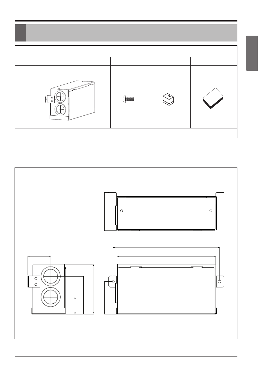
Item Auxliary Heater Relay Kit Screw Insulation Installation Manual
Q’ty 1 2 2 1
Model
2. Included Items
• PRARH1 applies to High Static Duct, Low Static Duct, 1Way CST, 2Way CST, 4Way CST and Ceiling
Suspended types.
(Unit : inch)
Figure
PRARH1
Included Items
1-13/32
1-7/16
2-19/32
2-19/32
7-9/32
6-23/32
3-13/32
2-7/32
Page 6
Aux heater
communication lines
6 Auxiliary Heater Relay Kit
Assembly Diagram
Check the distance between PRARH1 and a control box
when connecting anchor bolts.
9/16
Auxiliary Heater communication lines
(under AC24V,over AWG24)
These wires should not make
contact with high voltage lines.
To indoor unit PCB
(CN-PTC)
AB AB
Fig. A
Control box cover
screw
Insulation
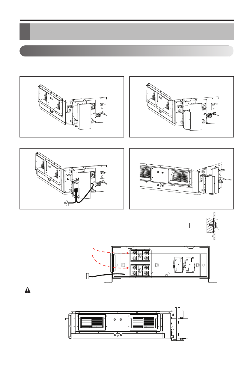
3. Assembly Diagram
n High Static Duct
※
Wiring
Note: While connecting the PRARH1, attach insulation at the rear of the control box cover
where it receives screws as shown in Fig. A.
Please clean up the remaining wires after installation.
Step1. Open control box cover. Step2. Assemble PRARH1 with control box cover.
Step3. Open the cover of PRARH1 and connect wires. Step4. Assemble control box cover.
Assembly Diagram - PRARH1
(Unit : inch)
CAUTION
Page 7

Assembly Diagram
Installation Manual 7
ENGLISH
n Low Static Duct
Check the distance between PRARH1 and the top of model
when connecting anchor bolts.
4 13/32
Auxiliary Heater communication lines
(under AC24V,over AWG24)
These wires should not make
contact with high voltage lines.
To indoor unit PCB
(CN-PTC)
AB AB
※
Wiring
Fig. A
Control box cover
screw
Insulation
Note: While connecting the PRARH1, attach insulation at the rear of the control box cover
where it receives screws as shown in Fig. A.
Please clean up the remaining wires after installation.
Aux heater communication lines
Step1. Open control box cover. Step2. Assemble PRARH1 with control box cover.
Step3. Open the cover of PRARH1 and connect wires. Step4. Assemble control box cover.
(Unit : inch)
CAUTION
Page 8

8 Auxiliary Heater Relay Kit
n 1 Way CST
Auxiliary Heater communication lines
(under AC24V,over AWG24)
These wires should not make
contact with high voltage lines.
To indoor unit PCB
(CN-PTC)
AB AB
※
Wiring
Assembly Diagram
Aux heater
communication
lines
Step1. Open front panel. Step2. Assemble PRARH1 with cabinet.
Step3. Open the cover of PRARH1 and connect wires. Step4. Assemble control box cover and front panel.
Fig. A
Control box cover
screw
Insulation
Note: While connecting the PRARH1, attach insulation at the rear of the control box cover
where it receives screws as shown in Fig. A.
Please clean up the remaining wires after installation.
Page 9

Installation Manual 9
ENGLISH
n 2 Way CST
Auxiliary Heater communication lines
(under AC24V,over AWG24)
These wires should not make
contact with high voltage lines.
To indoor unit PCB
(CN-PTC)
AB AB
※
Wiring
Assembly Diagram
Aux heater
communication
lines
Step1. Open front panel. Step2. Assemble PRARH1 with cabinet.
Step3. Open the cover of PRARH1 and connect wires. Step4. Assemble control box cover and front panel.
Fig. A
Control box cover
screw
Insulation
Note: While connecting the PRARH1, attach insulation at the rear of the control box cover
where it receives screws as shown in Fig. A.
Please clean up the remaining wires after installation.
Page 10

10 Auxiliary Heater Relay Kit
n 4 Way CST
Auxiliary Heater communication lines
(under AC24V,over AWG24)
These wires should not make
contact with high voltage lines.
To indoor unit PCB
(CN-PTC)
Aux heater
communication lines
AB AB
Check the attached direction to the indoor unit.
Aux heater
communication lines
※
Wiring
Assembly Diagram
Aux heater
communication lines
Aux heater
communication lines
Aux heaterAux heater
communication linescommunication lines
Aux heater
communication lines
Aux heater
communication lines
Step1. Open front panel. Step2. Assemble PRARH1 with cabinet.
Step3. Open the cover of PRARH1 and connect wires. Step4. Assemble control box cover and front panel.
CAUTION
Fig. A
Control box cover
screw
Insulation
Note: While connecting the PRARH1, attach insulation at the rear of the control box cover
where it receives screws as shown in Fig. A.
Please clean up the remaining wires after installation.
Page 11

Installation Manual 11
ENGLISH
Assembly Diagram
n Ceiling Suspended
D < 3.3ft
Auxiliary heater relay kit should be installed with in 3.3ft from the product.
Otherwise heater may cause malfunction.
Auxiliary Heater communication lines
(under AC24V,over AWG24)
These wires should not make
contact with high voltage lines.
To indoor unit PCB
(CN-PTC)
AB AB
※
Wiring
Aux heater
communication
lines
Step1. Mount relay kit on the wall. Step2. Connect wires and assemble cover.
Do not install PRARS0 at,
- Places which exposed to rain or any water.
Other wise it may leads to electric shock, fire, injury or sometimes even fatality.
CAUTION
CAUTION
Note: Please clean up the remaining wires after installation.
Page 12

12 Auxiliary Heater Relay Kit
4. Electrical Wiring
Electrical Wiring
rd
3
Party Scope
Hot Water
External Power supply
- Supply voltage : AC 24V
RADIATOR
LG Scope
Auxiliary Relay Kit
RADIATOR
Hot Water
Indoor Unit
CN_PTC
DC12V
AB AB
CN_PTC1
Page 13

Installation Manual 13
ENGLISH
Electrical Wiring
rd
3
Party Scope
Hot Water
External Power supply
- Supply voltage : AC 24V
RADIATOR
LG Scope
Indoor Unit
DC12V
Auxiliary Relay Kit
CN_PTC
AB AB
CN_PTC1
Page 14

14 Auxiliary Heater Relay Kit
Installer Setting
5. Installer Setting
• In the menu screen, press [<,>(left/right)] button to select the setting category, and press [∧(up)] button for
3 seconds to enter the password input screen for the installer setting.
• Input the password and press [OK] button to move to the installer setting list.
※Installer setting password
Main screen → menu → setting → service → RMC version information → SW Version
Example) SW version : 1.00.1 a
In the above case, the password is 1001.
Note: Some categories of the installer setting menu may not be available depending on the product function or the menu
name may be different.
The installer setting mode is the mode to set the remote controller’s detail function. If the installer
setting mode is incorrectly set, it may cause product failure, user’s injury, or property damage. It
must be set by the installation specialist with the installation license, and if it is installed or
changed without installation license, all problems caused will be the responsibility of the installer,
and may void the LG warrenty.
CAUTION
If you want to operate Auxiliary Heater Relay Kit, you should have Wired or Wireless Remote Controller
below.
Model : PREMBTB100
OK OK
Page 15

Installer Setting
Installation Manual 15
ENGLISH
At the Code field, select when air cleaner/heater/humidifier/elevation grill/ventilation KIT/Aux Heater/refrigerant leakage detection sensor are newly installed to the indoor unit or when an installed KIT is removed.
• You can set the following setting values using [<,>(left/right)] button.
Function Value
Plasma purification
Not install / Install
Heater
Humidifier
Elevation grill
Ventilation Kit
Aux Heater
Refrigerant leakage detection sensor
External devices of indoor unit setting (air conditioner)
Page 16

16 Auxiliary Heater Relay Kit
Installer Setting
It is a function that sets outdoor temperature values for two stage heating.
if user set outdoor temperature T1 and T2, Indoor unit will select heating stage between Indoor unit operation
and heater operation.
T<= T1 : Auxiliary heater operation only
T1<T<T2 : Simultaneous operation of auxiliary heater and heat pump
T>=T2 : Heat pump operation only
T1 Value T2 Value
-23 ~ 16 °C (-10 ~ 60 °F) -23 ~ 51 °C (-10 ~ 130 °F)
Outdoor temp. for heating stages (air conditioner)
OK
Page 17

Troubleshooting Guide
Installation Manual 17
ENGLISH
6. Troubleshooting Guide
Symptom Check Action
AUX HEATER
does not work.
Is air conditioner power turned on?
- Check the circuit breaker.
- Check the AUX HEATER RELAY KIT installation status.
Is the cable correctly connected beteween the air conditioner andAUX
HEATER RELAY KIT?
- Connect the cable between the air conditioner
and AUX HEATER RELAY KIT.
Is the cable correctly connected
between AUX HEATER and
AUX HEAER REWLAY KIT?
- Refer to the installation method in the installation manual and check again.
Is there any problem with wireless
remote controller?
(If wireless remote controller is used)
- Replace the battery or insert again according
to the polarity(+,-).
- If there is a leakage of the battery fluid in the
remote controller, replace the battery.
Page 18

Page 19

Page 20

 Loading...