

Page 1

OWNER’S &
INSTALLATION MANUAL
SIMPLE WIRED REMOTE
CONTROLLER
Please read this manual carefully before operating
your set and retain it for future reference.
P/NO : MFL62862002
www.lg.com
Models : PQRCVCL0Q
PQRCVCL0QW
ENGLISH
ITALIANO ESPAÑOL
FRANCAIS
DEUTSCH
PORTUGUESE
кмллдав ьбхд
Page 2

2 Wired Remote Controller
Simple Wired Remote Controller Ownerʼs & Installation Manual
TABLE OF CONTENTS
n Safety Precautions..................................................................3
n Part Description ......................................................................4
Simple Wired Remote Controller...............................................................4
n Installation Instruction........................................................5~6
Group control..............................................................................................7
Installer setting – How to enter installer setting mode ...........................8
Installer setting – Test Run Mode .............................................................9
Installer setting – Setting Address of Central Control ..........................10
Installer setting – E.S.P ............................................................................11
Installer setting – Thermistor .................................................................12
Installer setting – Ceiling Height Selection ............................................13
Installer setting – Static Pressure Setting .............................................14
Installer setting – Remote Controller Master/Slave Setup....................15
Installer setting – Celsius/Fahrenheit .....................................................16
n Owners instruction ...............................................................17
Standard Operation – Cooling Mode ......................................................17
Standard Operation – Heating Mode.......................................................18
Standard Operation – Auto Operation Mode..........................................19
Standard Operation – Dehumidification Mode.......................................20
Standard Operation – Fan Mode .............................................................21
Function Setting – Fan Speed Selection ................................................22
Function Setting – Room temperature check ........................................23
Function Setting – Child Lock .................................................................24
Function Setting – Auto Swing................................................................25
Function Setting – Vane Angle Control ..................................................26
Different mode drive.................................................................................27
Checkups before reporting breakdown..................................................28
Page 3
Safety Precaution
Ownerʼs & Installation Manual 3
ENGLISH
Be sure to request to the
service center or installation
specialty store when
installing products.
• It will cause fire or electric shock
or explosion or injury.
Request to the service center
or installation specialty store
when reinstalling the
installed product.
• It will cause fire or electric shock
or explosion or injury.
Do not disassemble, fix, and
modify products randomly.
• It will cause fire or electric shock.
Do not place flammable
stuffs close to the product.
• It will cause fire.
Do not allow water to run
into the product.
• It will cause electric shock or
breakdown.
Do not give the shock to the
product.
• It will cause breakdown when
giving the shock to the product.
n Installation
Safety Precaution
• The installation requires expert skills, and it should be installed by the service center or other shops specialized
in the installation and recognized by our company.
• For all the problems arising after installation by someone who has no relevant qualifications, our company will
not provide free service.
• The following safety cautions are provided to prevent unexpected dangers or losses.
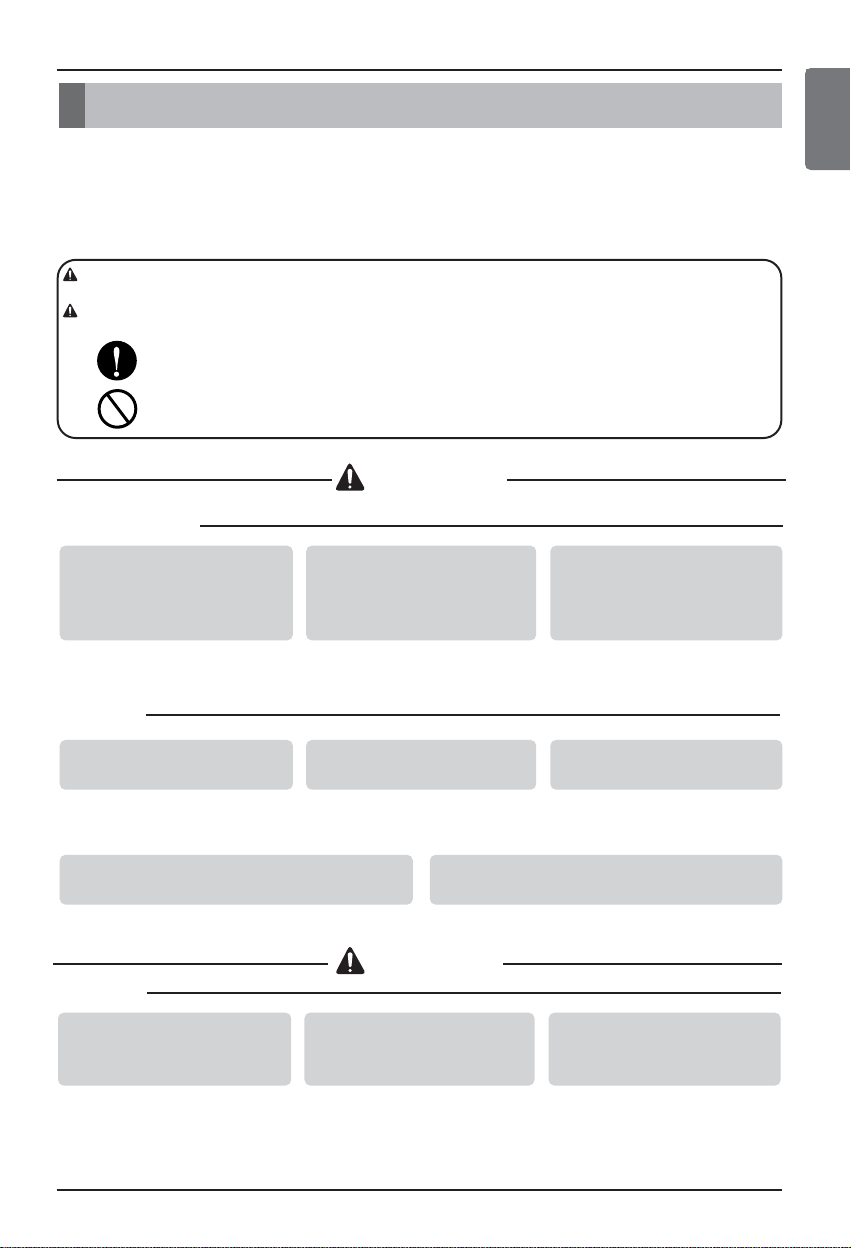
: If the user does not follow the mandatory items, it may result in serious injury or death.
: If the user does not follow the mandatory items, it may cause personal injury or property
damage.
: Warning and Caution are to call the userʼs attention to the possible danger. Read and follow
them carefully in order to prevent a safety accident.
: Warning and Caution are indicated in this guide and the product itself to help protect the users
from danger.
WARNING
n In-use
Request to the service center or installation
specialty store when the product becomes wet.
• It will cause fire or electric shock.
Do not give the shock using sharp and
pointed objects.
• It will cause breakdown by damaging parts.
n In-use
CAUTION
Do not clean using the
powerful detergent like
solvent but use soft cloths.
• It will cause fire or product
deformation.
Do not press the screen
using powerful pressure or
select two buttons.
• It will cause product breakdown or
malfunction.
Do not touch or pull the lead
wire with wet hands.
• It will cause product breakdown or
electric shock.
WARNING
CAUTION
Page 4
4 Wired Remote Controller
Part Description
Part Description
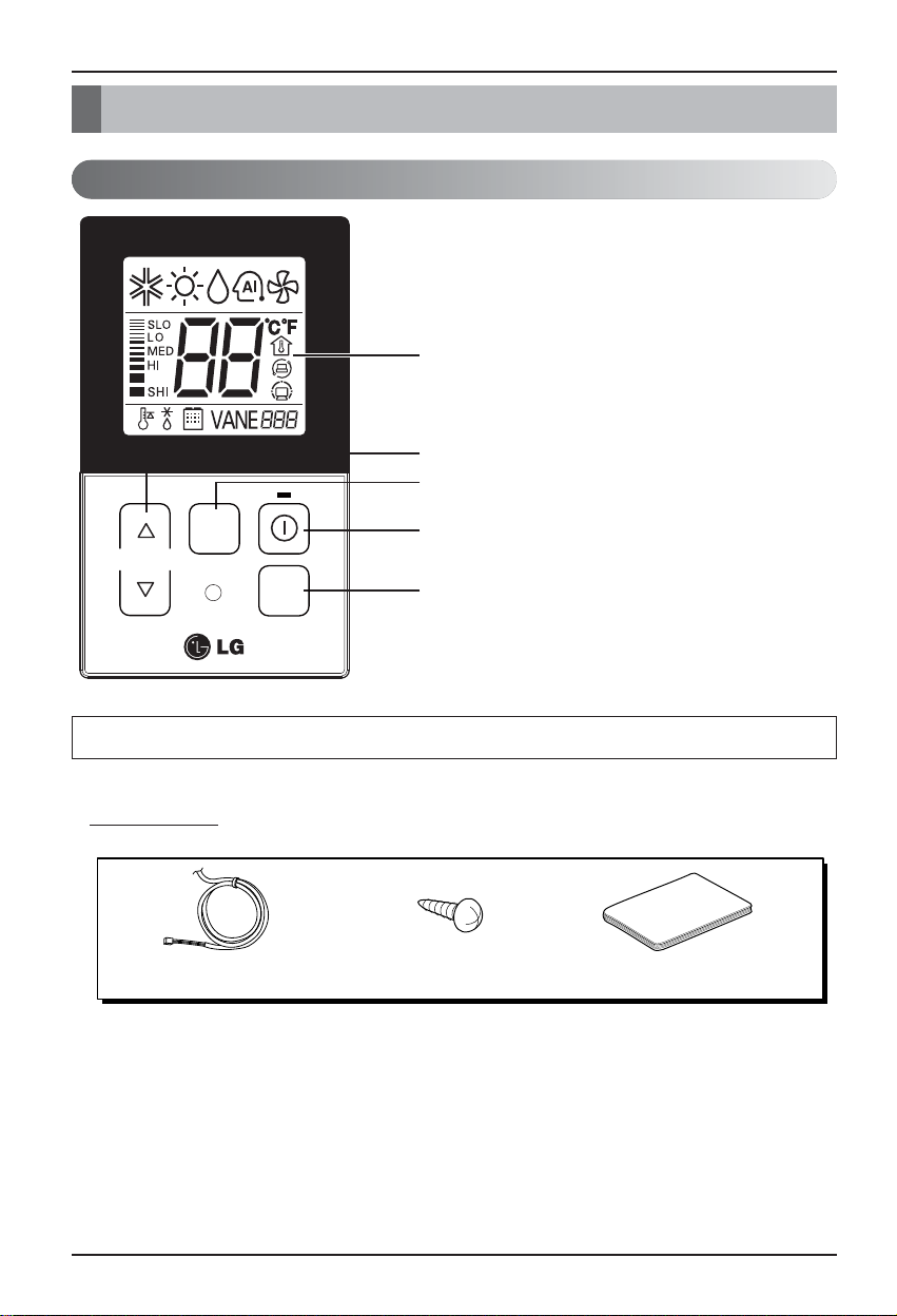
Accessory
Connecting Cable (1EA) Fixing Screw (2EA) Owner / Installation Manual
Simple Wired Remote Controller
Each function will be shown on the display panel for three seconds or so when the power is applied at first.
1. Operation Display Panel
2. Temperature Control Button
3. Fan Speed Button
4. On/Off Button
5. Operation Mode select Button
1
2
3
FAN
SPEED
TEMP
OPER
MODE
4
5
Page 5
Ownerʼs & Installation Manual 5
ENGLISH
Installation instruction
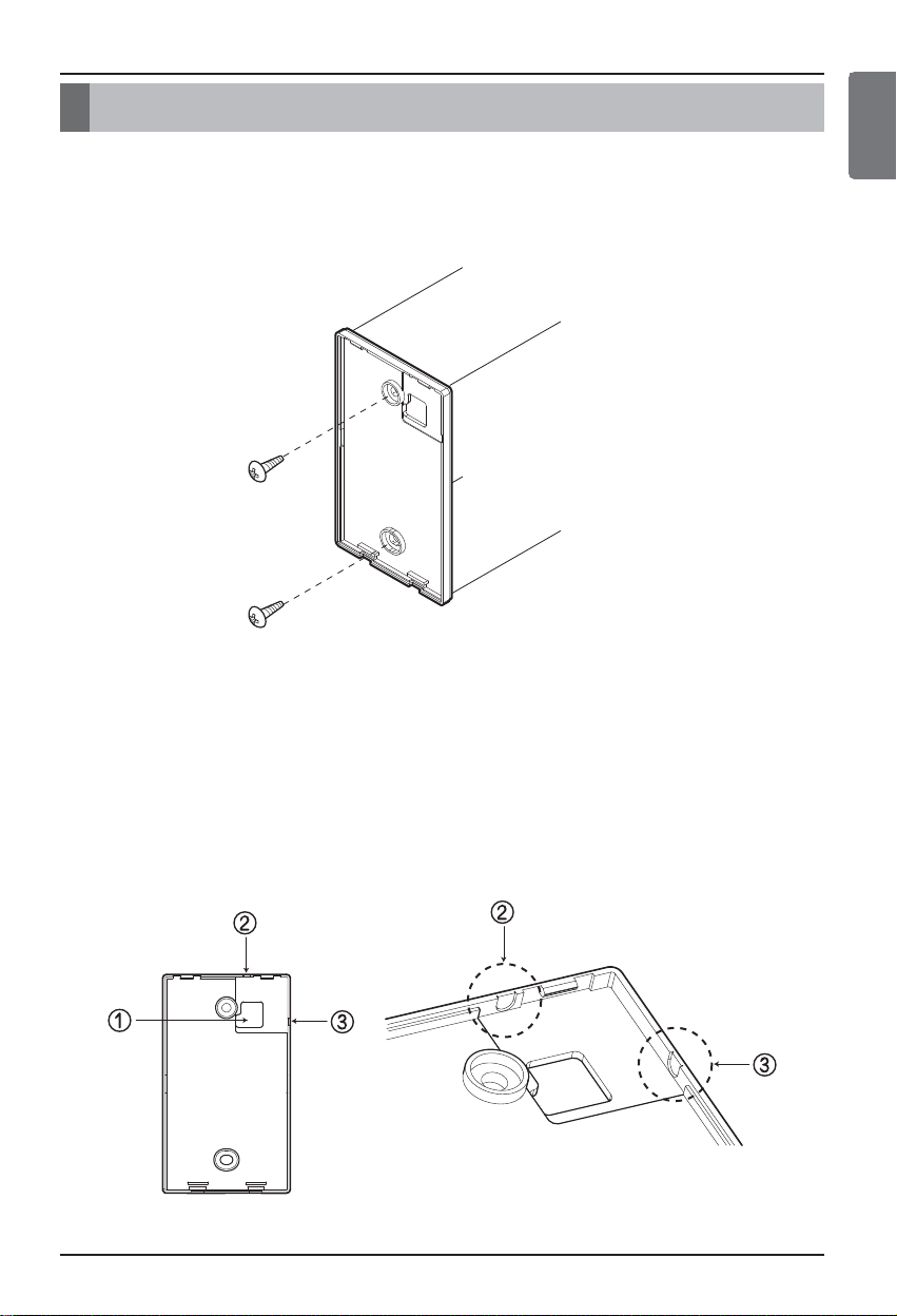
1. Please fix tightly using provided screw after placing remote controller setup board
on the place where you like to setup.
- Please set it up not to bend because poor setup could take place if setup board bends.
Please set up remote controller board fit to the reclamation box if there is a reclamation box.
2. Can set up Wired remote controller cable into three directions.
- Setup direction: the surface of wall reclamation, upper, right
- If setting up remote controller cable into upper and right side, please set up after removing remote controller
cable guide groove.
h
Remove guide groove with long nose.
①
Reclamation to the surface of the wall
②
Upper part guide groove
③
Right part guide groove
Installation instruction
<Wire guide grooves>
Page 6
Installation instruction
6 Wired Remote Controller
Wall
Side
Wall
Side
Wall
Side
Wall
Side
<Connecting order>
<Separating order>
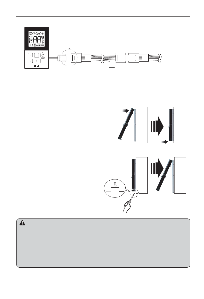
5. Please fix remote controller upper part into
the setup board attached to the surface of the
wall, as the picture below, and then, connect
with setup board by pressing lower part.
- Please connect not to make a gap at the remote controller
and setup boardʼs upper and lower, right and left part.
When separating remote controller from
setup board, as the picture below, after
inserting into the lower separating hole using
screw driver and then, spinning clockwise,
remote controller is separated.
- There are two separating holes. Please individually
separate one at a time.
- Please be careful not to damage the inside
components when separating.
3. Please connect indoor unit and remote controller using connection cable.
4. Please use extension cable if the distance between wired remote controller and
indoor unit is more than 10m.
Please check if connector is normally connected.
Connecting cable
Indoor
Unit side
TEMP
FAN
SPEED
OPER
MODE
When installing the wired remote controller, do not bury it in the wall.
(It can cause damage in the temperature sensor.)
Do not install the cable to be 50m or above.
(It can cause communication error.)
• When installing the extension cable, check the connecting direction of the connector of the remote controller
side and the product side for correct installation.
• If you install the extension cable in the opposite direction, the connector will not be connected.
• Specification of extension cable: 2547 1007 22# 2 core 3 shield 5 or above.
CAUTION
Page 7
Ownerʼs & Installation Manual 7
ENGLISH
Installation instruction
GND
GND
12V
Signal wire
Signal wire
TEMP
FAN
SPEED
OPER
MODE
GND
12V
B Y R B Y R
MASTER SLAVE
Signal wire
GND
12V
Signal wire
TEMP
FAN
SPEED
OPER
MODE
TEMP
FAN
SPEED
OPER
MODE
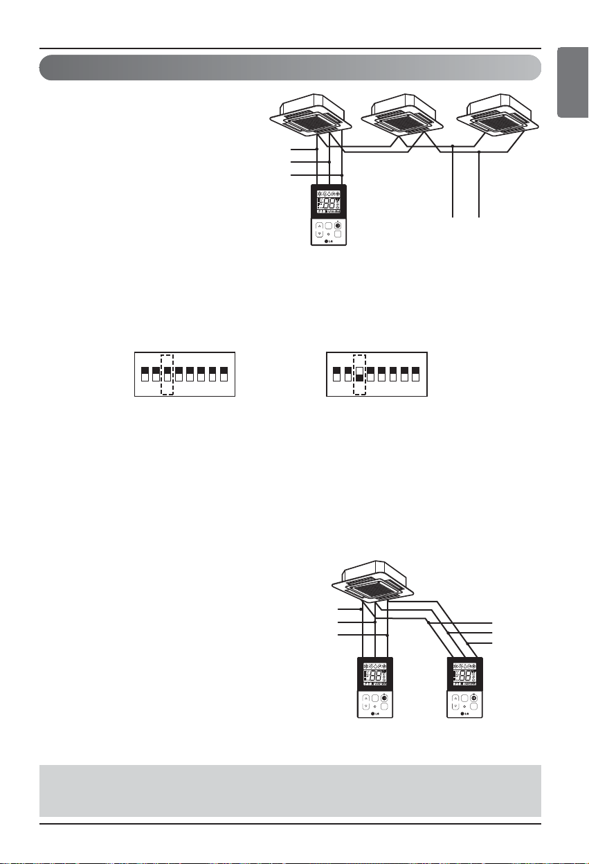
Group control
1. When installing more than 2
units of air conditioner to one
wired remote controller, please
connect as the right figure.
• If it is not event communication
indoor unit, set the unit as slave.
• Check for event communication
through the product manual.
2. When installing more than 2 wired
remote controllers to one air
conditioner, please connect as the
right picture.
• When installing more than 2 units of wired
remote controller to one air conditioner, set
one wired remote controller as master and
the others all as slaves, as shown in the
right picture.
• You cannot control the group as shown in
the right for some products.
•
Refer to the product manual for more detail.
When controlling multiple indoor units with event communication function with one remote
controller, you must change the master/slave setting from the indoor unit.
Indoor units, the master/slave configuration of the product after completion of indoor unit power
ʻOFFʼ and then ʻONʼ the power after 1 minutes elapsed sign up.
- For ceiling type cassette and duct product group, change the switch setting of the indoor PCB.
- For wall-mount type and stand type product, change the master/slave setting with the wireless
remote controller. (Refer to wireless remote controller manual for detail)
h When installing 2 remote controllers to one indoor unit with event communication function, set
the master/slave of the remote controller. (Refer to remote controller master/slave selection)
When controlling the group, some functions excluding basic operation setting, fan level
Min/Mid/Max, remote controller lock setting and time setting may be limited.
<When simultaneously connecting
2 sets of wired remote controller>
• When controlling in groups, set the master/slaver of the remote controller. Refer to
Installer setting section on how to set master/slave for more detail.
1ON2345 678 1ON2345 678
#3 switch OFF: Master
(Factory default setting)
#3 switch ON: Slave
Page 8
8 Wired Remote Controller
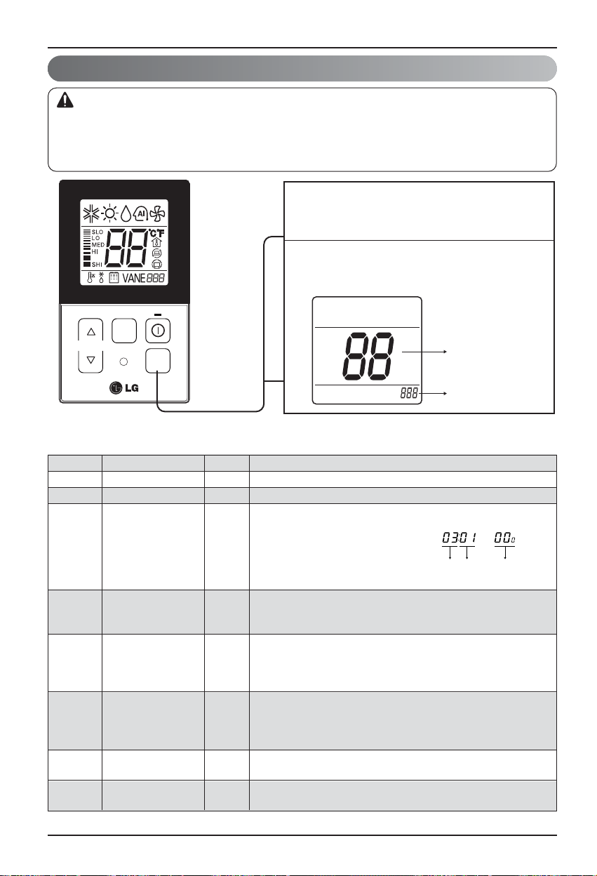
<Installer Setting Code Table>
1) General air-conditioner product
j Some contents may not be displayed depending on the product function
Installation instruction
Installer setting mode is to set the detail function of the remote controller.
If the installer setting mode is not set correctly, it can cause problems to the product, user injury or property
damage. This must be set by an certificated installer, and any installation or change that is carried out by a
non-certificated person should be responsible for the results. In this case, free service cannot be provided.
CAUTION
Installer Setting -How to enter installer setting mode
No. Function Code Value
1 Test Run 01 01:Set
2 Address Setting 02 00~FF : Address
<ESP Step> <ESP Value> <Example>
01:VeryLow 0 ~ 255
02:Low
3 E.S.P. Value 03
03:Med
04:High
05:Very High
01:Remo
4 Thermistor 04 02:Indoor
03:2TH
01:Med
02:Low
5 Ceiling Height 05
03:High
04:Very High
01:V-H
02:F-H
6 Static Pressure 06
03:V-L
04:F-L
7 Master Setting 07
00:Slave
01:Master
8
Celsius
12
00:Celsius
(Optimized only for U.S.A)
Fahrenheit Switching 01:Fahrenheit
If you want to set installer setting mode, Press
1
the Temperature up button and the oper mode
button same time for five seconds.
When you enter the setting mode
2
Initially. Function code is displayed
on the LCD screen.
FAN
SPEED
TEMP
OPER
MODE
Function Code
Value
Function Code ESP valueESP step
Page 9
Ownerʼs & Installation Manual 9
Installation instruction
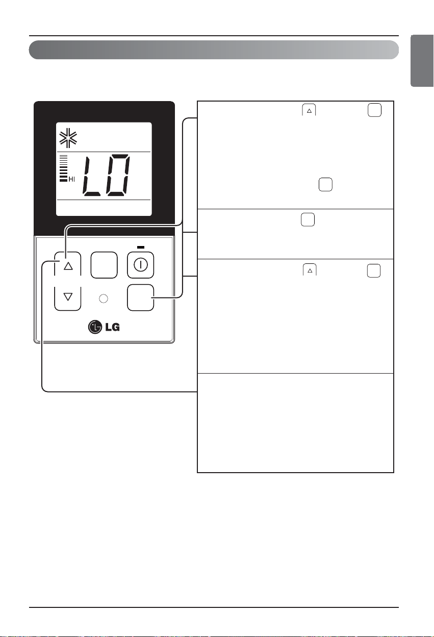
Installer Setting -Test Run Mode
After installing the product, you must run a Test Run mode.
For details related to this operation, refer to the product manual.
• What is the test run mode??
- This means the operation of the product under the cooling, strong wind, and Comp on state
without performing room temperature control in order to confirm the installed state during the
product installation.
ENGLISH
When pressing the button and
1
button simultaneously for more than 3
seconds, the system will be entered
into the installer setting mode.
- After entering into the installer setting
mode, select the test run mode code
value by pressing the button.
* Test run mode code value : 01
OPER
MODE
OPER
MODE
When pressing the button, the test
2
operation mode will be performed, and it
OPER
MODE
is displayed as shown in the left figure.
TEMP
FAN
SPEED
OPER
MODE
When pressing the button and
3
button simultaneously for more than 3
seconds after the setting has been
completed, the setting mode will be
OPER
MODE
released.
- If there isn’t any button input for more
than 25 seconds, the installer setting
mode will also be released.
When approx. 18 minutes are elapsed
4
after starting of the test oper-mode, the
system will be stopped automatically
and converted to the standby state.
- If any button is inputted during the test
run mode, the test run mode will be
forced to be relreased.
Page 10

10 Wired Remote Controller
Installation instruction
* In the case when the lock is set up at the central controller, ʻHLʼ will be indicated on the display
window of the wired remote controller and the indoor unit will not be controlled by the remote
controller.
It's the function to use for connecting central control.
Please refer to central controller manual for the details
Installer Setting - Setting Address of Central Control
• If you connect the indoor unit to the central controller, you should set the network address
of the indoor unit so that the central controller could recognize it.
• The center-control address is composed of the group number and the indoor-unit number.
Note : The remote controller displays 'HL' if central controller has locked the remote controller .
OPER
OPER
MODE
MODE
TEMP
FAN
SPEED
OPER
MODE
When pressing the button and
1
button simultaneously for more than 3
seconds, the system will be entered into the
installer setting mode.
-
After entering into the installer setting mode,
select the central control address setting
code value by pressing the button.
* Setting address of central control code
value : 02
Set up the group nember and indoor unit with
2
the temperature adjustment(▲,▼) buttons.
TEMP
Group number
Indoor unit number
For example, when setting as
[ Group number=2 Indoor number=3 ]
it will be displayed as shown in the left figure.
When pressing the button, the system
3
will be set up with the address value which
has been established at present.
When pressing the button and
4
button simultaneously for more than 3
OPER
MODE
seconds after the setting has been
completed, the setting mode will be released.
- If there isn’t any button input for more than
25 seconds, the installer setting mode will
also be released.
Page 11

Ownerʼs & Installation Manual 11
ENGLISH
Installer Setting -E.S.P.
• If you set ESP incorrectly, the air conditioner may malfunction.
• This setting must be carried out by a certificated-technician.
This is the function that decides the strength of the wind for each wind level and because this
function is to make the installation easier.
Installation instruction
•
Precaution shall be taken not to alter the E.S.P value corresponded to each air flow section.
•
E.S.P value can be varied according to the products.
•
In the case of going to the next air flow rate stage by pressing the fan-speed button during the
setup of the E.S.P value, the E.S.P value of previous air flow rate will be maintained by
remembering the E.S.P value prior to the shift.
OPER
MODE
TEMP
FAN
SPEED
OPER
MODE
When pressing the button and
1
button simultaneously for more than 3
seconds, the system will be entered into
the installer setting mode.
- After entering into the installer setting
mode, select the E.S.P code value by
pressing the button.
* E.S.P code value : 03
Select the desired air flow rate with
2
3
FAN
SPEED
the button. Whenever pressing
FAN
the button, [SLo
SPEED
will be indicated.
Select the desired air flow rate value
with the temperature up(▲), down(▼)
button.
* E.S.P value range : 0~255
-
E.S.P value will be indicated at the upper
right section of the display window.
OPER
MODE
→Lo→
Med→Hi→Po]
When pressing the button, currently
4
established E.S.P value will be set up.
When pressing the button and
5
button simultaneously for more than 3
seconds after the setting has been
completed, the setting mode will be released.
- If there isn’t any button input for more
than 25 seconds, the installer setting
mode will also be released.
OPER
MODE
Page 12

12 Wired Remote Controller
Installation instruction
• As the characteristic of the ʻ2THʼ function can be different in accordance with the
products, refer to the product instruction manual for its detail.
Installer Setting -Thermistor
This is the function to select the temperature sensor to judge the room temperature.
When pressing the button and
1
button simultaneously for more than 3
seconds, the system will be entered into
the installer setting mode.
- After entering into the installer setting
mode, select the thermistor sensor
setting code value by pressing the
button.
* Thermistor sensor selection code
value : 04
Select the desired setting value with the
2
FAN
SPEED
TEMP
OPER
MODE
temperature up(▲), down(▼) button.
*Setting value
01: Remote
controller
Code value
Val ue
02: Indoor unit
03: 2TH
OPER
MODE
OPER
MODE
When pressing the button, currently
3
established thermistor sensor location
will be set up.
OPER
When pressing the button and
4
button simultaneously for more than 3
MODE
seconds after the setting has been
completed, the setting mode will be
released.
- If there isn’t any button input for more
than 25 seconds, the installer setting
mode will also be released.
Page 13

Ownerʼs & Installation Manual 13
ENGLISH
Installation instruction
Installer Setting -Ceiling Height Selection
This function is to adjust FAN Airflow rate according to ceiling height (For ceiling type product)
• Ceiling height setting is available only for some products.
• Ceiling height of ʻVery highʼ function may not exist depending on the indoor unit.
• Refer to the product manual for more details.
Ceiling Height Level Description
01 Low Decrease the indoor airflow rate 1 step from standard level
02 Standard Set the indoor airflow rate as standard level
03 High Increase indoor airflow rate 1 step from standard level
04 Very high Increase indoor airflow rate 2 steps from standard level
<Ceiling Height Selection Table>
• As the ceiling height setting standard can
be different in accordance with the
products, refer to the product instruction
manual for its detail.
OPER
OPER
MODE
MODE
When pressing the button and
1
button simultaneously for more than 3
seconds, the system will be entered into
the installer setting mode.
- After entering into the installer setting
mode, select the ceiling height setting
code value by pressing the button.
* Ceiling height setting code value : 05
Select the desired setting value with the
2
temperature up(▲), down(▼) button.
*Setting value
01: Low
02: Standard
03: High
04: Very high
TEMP
FAN
SPEED
OPER
MODE
Code value
Val ue
When pressing the button, currently
3
established ceiling height value will be
set up.
OPER
When pressing the button and
4
button simultaneously for more than 3
MODE
seconds after the setting has been
completed, the setting mode will be released.
- If there isn’t any button input for more
than 25 seconds, the installer setting
mode will also be released.
Page 14

14 Wired Remote Controller
Installation instruction
Installer Setting -Static Pressure Setting
This function is applied to only duct type. Setting this in other cases will cause malfunction.
Pressure selection
Function
Zone state ESP standard value
01 V-H Variable High
02 F-H Fixed High
03 V-L Variable Low
04 F-L Fixed Low
<Static Pressure Setting Table>
OPER
When pressing the button and
1
button simultaneously for more than 3
seconds, the system will be entered into
the installer setting mode.
-
After entering into the installer setting
mode, select the ceiling height setting code
value by pressing the oper-mode button.
* Static pressure setting code value : 06
Select the desired setting value with the
2
temperature up(▲), down(▼) button.
MODE
FAN
SPEED
TEMP
OPER
MODE
When pressing button, currently
3
established static pressure value will be
set up.
When pressing the button and
4
button simultaneously for more than 3
seconds after the setting has been
completed, the setting mode will be released.
- If there isn’t any button input for more than
25 seconds, the installer setting mode will
also be released.
Code value
Val ue
*Setting value
01:V-H
02:F-H
03:V-L
04:F-L
OPER
MODE
Page 15

Ownerʼs & Installation Manual 15
ENGLISH
Installation instruction
Installer Setting-Remote Controller Master/Slave Setup
When pressing the button and
button simultaneously for more than 3
seconds, the system will be entered into the
installer setting mode.
- After entering into the installer setting
mode, select the ceiling height setting code
value by pressing the oper-mode button.
* Remote controller master/slave setting
code value : 07
1
Select the desired setting value with the
temperature up(▲), down(▼) button.
2
When pressing the button, currently
established static pressure value will be
set up.
3
When pressing the button and
button simultaneously for more than 3
seconds after the setting has been
completed, the setting mode will be released.
- If there isn’t any button input for more than
25 seconds, the installer setting mode will
also be released.
4
OPER
MODE
Code value
*Setting value
00:Slave
01:Master
OPER
MODE
Val ue
TEMP
FAN
SPEED
OPER
MODE
It is a function for settings in group control, or 2-remote controller control.
Remote controller Function
Master
Indoor unit operates based on master remote controller at group control.
(Master is set when delivering from the warehouse.)
Slave
Setup all remote controllers except one master remote controller to slave at
group control
• When controlling in groups, basic operation settings, airflow strength weak/medium/strong,
lock setting of the remote controller, time settings, and other functions may be restricted.
h Refer to the 'group control' part for details
Page 16

16 Wired Remote Controller
Installation instruction
• Whenever press temp up(s), down(t) button in Fahrenheit mode, the temperature will
increase/drop 2 degrees.
Installer Setting-Celsius / Fahrenheit Switching
This function is used for switching the display between Celsius and Fahrenheit.
(Optimized only for U.S.A)
When pressing the button and
1
button simultaneously for more than 3
seconds, the system will be entered into the
installer setting mode.
- After entering into the installer setting
mode, select the ceiling height setting code
value by pressing the oper-mode button.
* Celsius/Fahrenheit setting code value : 07
Select the desired setting value with the
2
temperature up(▲), down(▼) button.
OPER
MODE
FAN
SPEED
TEMP
OPER
MODE
When pressing button, currently
3
established celsius/Fahrenheit setting
value will be set up.
When pressing the button and
4
button simultaneously for more than 3
seconds after the setting has been
completed, the setting mode will be released.
- If there isn’t any button input for more than
25 seconds, the installer setting mode will
also be released.
Code value
Val ue
*Setting value
00:Celsius
01:Fahrenheit
OPER
MODE
Page 17

Ownerʼs & Installation Manual 17
ENGLISH
Standard Operation - Cooling Mode
Owner's instruction
Owner's instruction
It cools the room by comfortable and clean wind.
Cooling operation will begin if you press
1
the button.
Press the temperature button and set the
2
desired room temperature lower than the
current room temperature.
TEMP
-
Setting temp range : 18°C~30°C (64°F~86°F)
FAN
SPEED
TEMP
OPER
MODE
- If the desired temperature is set higher than
the current room temperature, the cooling
function will not begin and just the blowing
operation will continue.
If you prees the mode button during the
3
operation, the operation mode will be
changed in the order of cooling,
dry(dehumidification),heating,auto-operation
and fan operation.If the product is a
cooling-only model, the operation mode will
be changed in the order of cooling,
dry(dehumidification), auto-operation and fan
operation.
A click of the button will increase the
desired temperature by 1°C or 2°F.
A click of the button will decrease the
desired temperature by 1°C or 2°F.
If you press the button, the cooling
4
operation will stop.
Page 18

18 Wired Remote Controller
Owner's instruction
It supplies warm wind to the indoor
Standard Operation - Heating Mode
What is the three-minute delay function?
It will take time for the product to blow warm air. The delay is to protect the compressor.
The room will be heated with warm air after three minutes when the compressor begins
operation.
n The cooling-only model will not do heating function.
If you want to set the heating operation,
1
press the button. And press the
button.
Set the desired room temperature higher
2
than the current room temperature.
TEMP
-
Setting temp range : 16°C~30°C (60°F~86°F)
FAN
SPEED
TEMP
OPER
MODE
- If the desired temperature is set lower than
the current room temperature, the heating
function will not begin.
If you prees the mode button during the
3
operation, the operation mode will be
changed in the order of cooling,
dry(dehumidification),heating,auto-operation
and fan operation.
OPER
MODE
A click of the button will increase the
desired temperature by 1°C or 2°F.
A click of the button will decrease the
desired temperature by 1°C or 2°F.
If you press the button, the cooling
4
operation will stop.
Page 19

Ownerʼs & Installation Manual 19
ENGLISH
Standard Operation - Auto Operation Mode
Owner's instruction
After operating the product by pressing
1
TEMP
FAN
SPEED
OPER
MODE
the button, set up the auto operation
by pressing the button.
“Auto Change Over Mode” – Heat pump model only
2
When desired the set temperature is higher than the
room temperature during the auto operation
=> Heating operation
[For Heat pump models only]
When desired the set temperature is lower than the
room temperature during the auto operation
=> Cooling operation
- Setting temp range : 18°C~30°C (64°F~86°F)
“Auto Operation Mode”
3
For the products with the exclusive purpose
of cooling only, “AI” is indicated at the
temperature display section.
OPER
MODE
When cold
When cool
When appropriate
When warm
When hot
Page 20

20 Wired Remote Controller
Owner's instruction
Standard Operation - Dehumidification Mode
It removes humidity while air-cooling weakly.
• In rainy season or high humidity climate, it is possible to operate simultaneously dehumidifier and
cooling mode to remove humidity effectively.
• The menu item of wind powerfulness might not be partially selected according to the product.
After operating the product by pressing
1
the button, set up the dry
(Dehumidification) by pressing the
button.
When the dry operation is selected, “dh” will
2
be shown on the display window as shown
on the left side.
- The temperature setting can not be
adjusted during operation this mode.
FAN
SPEED
TEMP
FAN
SPEED
OPER
MODE
Press the button to select airflow rate
3
[SLo→Lo→Med→Hi→Po].
- The initial wind powerfulness of humidity
removal drive is ‘weak’.
OPER
MODE
Page 21

Ownerʼs & Installation Manual 21
ENGLISH
Owner's instruction
Standard Operation - Fan Mode
It blows the air as it is in the indoor, not the cold wind.
• Ventilation drive does not release cool wind but general fan
• Because it releases the wind that has no temperature difference from the room, it functions to
circulate the inside air.
• The menu item of wind powerfulness might not be partially selected according to the product.
After operating the product by pressing
1
the button, set up the fan operation by
pressing the button.
When the dry operation is selected, “Fn” will
2
be shown on the display window as shown
on the left side.
- The temperature setting can not be
adjusted during operation this mode.
Press the button to select airflow rate
3
FAN
SPEED
TEMP
OPER
MODE
[SLo→Lo→Med→Hi→Po].
When running ventilation, compressor of
AHU doesn’t work.
FAN
SPEED
OPER
MODE
Page 22

22 Wired Remote Controller
Owner's instruction
Function Setting - Fan Speed Selection
It blows the air as it is in the indoor, not the cold wind.
Select the proper fan speed which you want
1
by pressing the button on the remote
controller.
- If you press the button, the fan speed
will change in the order of [SLo→Lo→Med→
Hi→Po].
- The initial fan speed is “Hi”.
- If the product is not compatible with the fan
speed Control, it will not function as per
your selection.
Fan Speed Selection in Cooling Operation
FAN
SPEED
TEMP
OPER
MODE
Lo
FAN
SPEED
Med
Hi
Po
Fan Speed Selection in Heating, Dry, Fan,
Auto-Operation
Lo
Med
Hi
Page 23

Ownerʼs & Installation Manual 23
ENGLISH
Owner's instruction
Function Setting - Room Temperature Check
* As the temperature distribution of the remote controller Installation space is not uniform,
slight difference can be Generated between the actually felt temperature and the room
temperature indication of the remote controller.
FAN
SPEED
TEMP
FAN
SPEED
OPER
MODE
When prssing the button of the remote
1
controller Adjustment section for approx. 3
seconds, the room Temperature will be
indicated for about 5 seconds
Before resuming to the previous display
panel.
In the case of the room temperature display,
the room Temperature can be different in
accordance with the Setting of the remote
controller’s room temperature
Detection selection.
Page 24

24 Wired Remote Controller
Owner's instruction
It is the function to use preventing children or others from careless using.
Function setting - Child Lock
TEMP
FAN
SPEED
OPER
MODE
During the operation, when pressing the
button and button for approx. 3 seconds,
the ‘Child Lock’ Function can be used.
-
At the time of initial setting of the ‘Child Lock’,
the ‘CL’ Will be indicated approx. 3 seconds
at the temperature Display section before
resuming to the previous mode.
After the setting of the ‘CL’, if another button
is setup, the button can not be recognized as
the ‘CL’ is indicated at the temperature
display section for approx. 3 seconds.
1
If the ‘CL’ function is wanted to be used
under the operation standby state, press the
button and Button for approx.
3 seconds under the standby mode state and
the system will be the ‘CL’ state.
2
As for the releasing method, when pressing
the Button and button for approx. 3
seconds, the ‘CL’ function can be released.
3
FAN
SPEED
FAN
SPEED
FAN
SPEED
Page 25

Ownerʼs & Installation Manual 25
ENGLISH
Function setting - Auto Swing
This function is to adjust angle at which airflow is blow out.
TEMP
FAN
SPEED
OPER
MODE
During the operation, when pressing the
button and button for approx. 3
seconds, the ‘Auto Swing’ function can be
1
During the operation of the ‘Auto Swing’
function, when pressing the button and
button simultaneously for approx. 3
seconds, the ‘Auto Swing’ function can be
released.
- This function is not indicated on the wired
remote controller even if the product is
actually operated.
- This function may not be performed in
accordance with the products.
2
OPER
MODE
OPER
MODE
Owner's instruction
Page 26

26 Wired Remote Controller
Owner's instruction
This function is to adjust angle at which airflow is blow out.
Function setting - Vane Angle Control
TEMP
FAN
SPEED
OPER
MODE
When pressing the button for approx. 3
seconds during the operation, the vane angle
control setting function can be used.
1
Initial ‘vane1’ is indicated at the window
panel upper section and the system
becomes the setting mode as ‘P0’ is
indicated at the temperature display section.
2
Select the vane angle number from ‘vane1’
to ‘vane4’ by pressing the button.
- When selecting the vane number, the vane
which is corresponded to the number will be
opened and closed.
3
Select the vane angle from ‘P0’ to ‘P6’ with
the temp up/down button.
- In the case of the wind flowing out angle,
(Minimum angle)…………….(Max angle)
‘ P0 < P1 < P2 < P3 < P4 < P5 < P6 ’
4
When pressing the button for 3 seconds,
the setting is finished and the vane angle
control setting is completed.
- If there isn’t any button input for approx. 60
seconds after the setting, the system will
be coming out of the vane angle control
setting mode automatically.
5
OPER
MODE
OPER
MODE
OPER
MODE
* Vane number and the angle of wind can be selected differently in accordance with the
products.
Page 27

Ownerʼs & Installation Manual 27
ENGLISH
Different mode drive
Different mode drive is a phenomenon taking place when indoor units' drive mode is different in the
case that a few indoor units are set up at one AHU.
(Different mode drive doesn't show up at cooling exclusive model.)
Owner's instruction
• If the product is not compatible with the different mode operation, LCD will be displayed
ʻCH07ʼ.
• If ʻCH07ʼ is displayed, please change the mode.
• Different mode operation is not error.
If one indoor unit operate heating mode while
1
several indoor units are operating cooling
mode, outdoor segment and cooling segment
are blinking like display on the left.
=> It means operation of cooling mode in
outdoor unit.
If one indoor unit operate cooling or
2
dehumidification mode while several indoor
units are operating heating mode, outdoor
segment and cooling segment are blinking.
=> It means operation of heating mode in
outdoor unit.
If pressing button, indoor unit
automatically runs at the mode that different
indoor units are running after about 5
seconds and operates.
TEMP
FAN
SPEED
OPER
MODE
3
Page 28

28 Wired Remote Controller
Checkups before reporting breakdown
Please first check the items below for product's defects before consulting to service center.
Symptoms
• Is air-conditioner's power on?
• Are air-conditioner and remote
controller properly connected
with cable?
• Is cable connection correct?
• Did you correctly setup time?
• Did you correctly make a
reservation?
• Is desired temperature setup
lower than current temperature?
• Isn't reservation drive setup?
• Does remote controller indication
window indicate 'CH03'?
It has no power
on.
It doesn't operate
reservation drive.
It doesn't release
cool wind.
Air-conditioner
automatically runs
or stops.
Error is indicated
on remote
controller
indication window.
• Please check up circuit breaker.
• Please check up wire remote controller's
setup condition.
• Please connect air-conditioner and remote
controller cable.
• Please check again referring to setup
method at the manual.
• Please set up current time correctly.
• Please set up again referring to the
manual.
• Please set up desired temperature lower
than current temperature.
• Please cancel reservation drive.
• Please check again wire remote
controller's setup condition.
• Please check again connection condition
of air-conditioner and remote controller
cable.
ManagementCheck-up
Owner's instruction
Page 29

 Loading...