

Page 1

ENGLISH
www.lg.com
Please read this manual carefully before operating your set and retain it for future
reference.
SIMPLE WIRED REMOTE CONTROLLER
Original instruction
PQRCVCL0Q
PQRCVCL0QW
OWNER’S &
INSTALLATION MANUAL
AIR
CONDITIONER
[
Representative] LG Electronics Inc. EU Representative : LG Electronics European Shared Service Center B.V.
Krijgsman 1, 1186 DM Amstelveen, The Netherlands
[
Manufacturer] LG Electronics Inc. Changwon 2nd factory 84, Wanam-ro, Seongsan-gu, Changwon-si,
Gyeongsangnam-do, KOREA
Copyright © 2017 - 2020 LG Electronics Inc. All Rights Reserved.
MFL70261401
Rev.02_070720
ITALIANO ESPAÑOL
FRANCAIS DEUTSCH
PORTUGUÊS
кмллдав ьбхд
Page 2

Simple Wired Remote Controller Owner’s & Installation Manual
TABLE OF CONTENTS
n Safety Precautions..................................................................3
n Part Description ......................................................................4
Simple Wired Remote Controller...............................................................4
n Installation Instruction............................................................5
Remote controller installation ...................................................................8
Group control..............................................................................................9
Installer setting - How to enter installer setting mode ..........................10
Installer setting - Test Run Mode ............................................................12
Installer setting - Setting Address of Central Control...........................13
Installer setting - E.S.P.............................................................................14
Installer setting - Thermistor ..................................................................15
Installer setting - Ceiling Height Selection.............................................16
Installer setting - Static Pressure Setting ..............................................17
Installer setting - Remote Controller Master/Slave Setup.....................18
Installer Setting - Celsius / Fahrenheit Switching .................................19
Installer Setting - Celsius Control Setting..............................................20
Installer Setting - Setting for Refrigerant Leak Detector.......................21
Installer Setting - Static Pressure Step Setting .....................................22
Installer Setting - CN_EXT setting...........................................................23
Installer Setting - Auto ESP .....................................................................24
n Owners instruction ...............................................................26
Standard Operation - Cooling Mode .......................................................26
Standard Operation - Heating Mode .......................................................27
Standard Operation - Auto Operation Mode ..........................................28
Standard Operation - Dehumidification Mode .......................................29
Standard Operation - Fan Mode ..............................................................30
Function Setting - Fan Speed Selection .................................................31
Function Setting - Room temperature check .........................................32
Function Setting - Child Lock..................................................................33
Function Setting - Auto Swing ................................................................34
Function Setting - Vane Angle Control...................................................35
Different mode drive.................................................................................36
WLAN(Wireless LAN) Module Access Point Mode................................37
Self-diagnosis for Trouble Mode.............................................................38
Outage Compensation Function .............................................................38
Checkups before reporting breakdown..................................................39
2 Wired Remote Controller
Page 3
Safety Precaution
WARNING
CAUTION
WARNING
CAUTION
ENGLISH
Safety Precaution
• The installation requires expert skills, and it should be installed by the service center or other shops specialized
in the installation and recognized by our company.
• For all the problems arising after installation by someone who has no relevant qualifications, our company will
not provide free service.
• The following safety cautions are provided to prevent unexpected dangers or losses.
: If the user does not follow the mandatory items, it may result in serious injury or death.
: If the user does not follow the mandatory items, it may cause personal injury or property damage.
: Warning and Caution are to call the user’s attention to the possible danger. Read and follow them
carefully in order to prevent a safety accident.
: Warning and Caution are indicated in this guide and the product itself to help protect the users
from danger.
n Installation
Be sure to request to the
service center or installation
specialty store when
installing products.
• It will cause fire or electric shock
or explosion or injury.
Request to the service center
or installation specialty store
when reinstalling the
installed product.
• It will cause fire or electric shock
or explosion or injury.
n In-use
Do not place flammable
stuffs close to the product.
• It will cause fire.
Request to the service center or installation
specialty store when the product becomes wet.
• It will cause fire or electric shock.
Do not allow water to run
into the product.
• It will cause electric shock or
breakdown.
Do not give the shock using sharp and
pointed objects.
• It will cause breakdown by damaging parts.
n Installation
If anyone other than a licensed professional
installs, repairs, or alters LGElectronics air
conditioning products, the warranty is voided.
• All costs associated with repair are then the full
responsibility of the owner.
Do not install the unit in potentially
explosive atmospheres.
n In-use
Do not disassemble, fix, and
modify products randomly.
• It will cause fire or electric shock.
Do not give the shock to the
product.
• It will cause breakdown when
giving the shock to the product.
Do not clean using the
powerful detergent like
solvent but use soft cloths.
• It will cause fire or product
deformation.
Do not press the screen
using powerful pressure or
select two buttons.
• It will cause product breakdown or
malfunction.
Owner’s & Installation Manual 3
Do not touch or pull the lead
wire with wet hands.
• It will cause product breakdown or
electric shock.
Page 4
Part Description
TEMP
FAN
SPEED
OPER
MODE
2
3
4
5
1
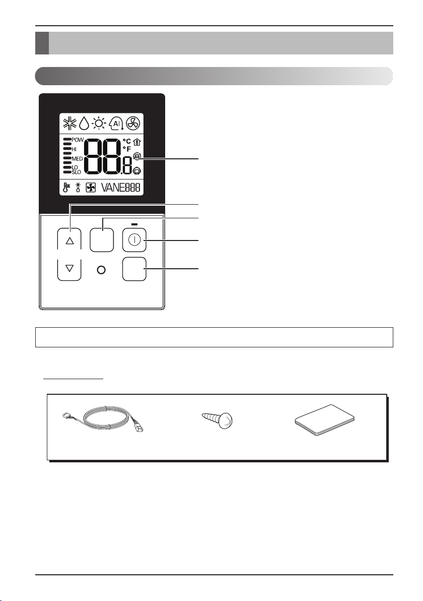
Part Description
Simple Wired Remote Controller
1. Operation Display Panel
2. Temperature Control Button
3. Fan Speed Button
4. On/Off Button
5. Operation Mode select Button
Each function will be shown on the display panel for three seconds or so when the power is applied at first.
Accessory
Connecting Cable (1EA) Fixing Screw (2EA) Quick Guide
4 Wired Remote Controller
Page 5
Installation instruction
ENGLISH
Installation instruction
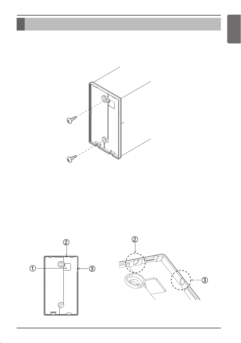
1. Please fix tightly using provided screw after placing remote controller setup board
on the place where you like to setup.
- Please set it up not to bend because poor setup could take place if setup board bends.
Please set up remote controller board fit to the reclamation box if there is a reclamation box.
2. Can set up Wired remote controller cable into three directions.
- Setup direction: the surface of wall reclamation, upper, right
- If setting up remote controller cable into upper and right side, please set up after removing remote controller
cable guide groove.
h
Remove guide groove with long nose.
①
Reclamation to the surface of the wall
②
Upper part guide groove
③
Right part guide groove
<Wire guide grooves>
Owner’s & Installation Manual 5
Page 6
Installation instruction
Wall
Side
Wall
Side
Wall
Side
Wall
Side
<Connecting order>
<Separating order>
Please check if the connectors are connected properly.
C/BOX Cable (Plug type)
Extension cable(housing type)
Indoor
Unit side
TEMP
FAN
SPEED
OPER
MODE
CAUTION
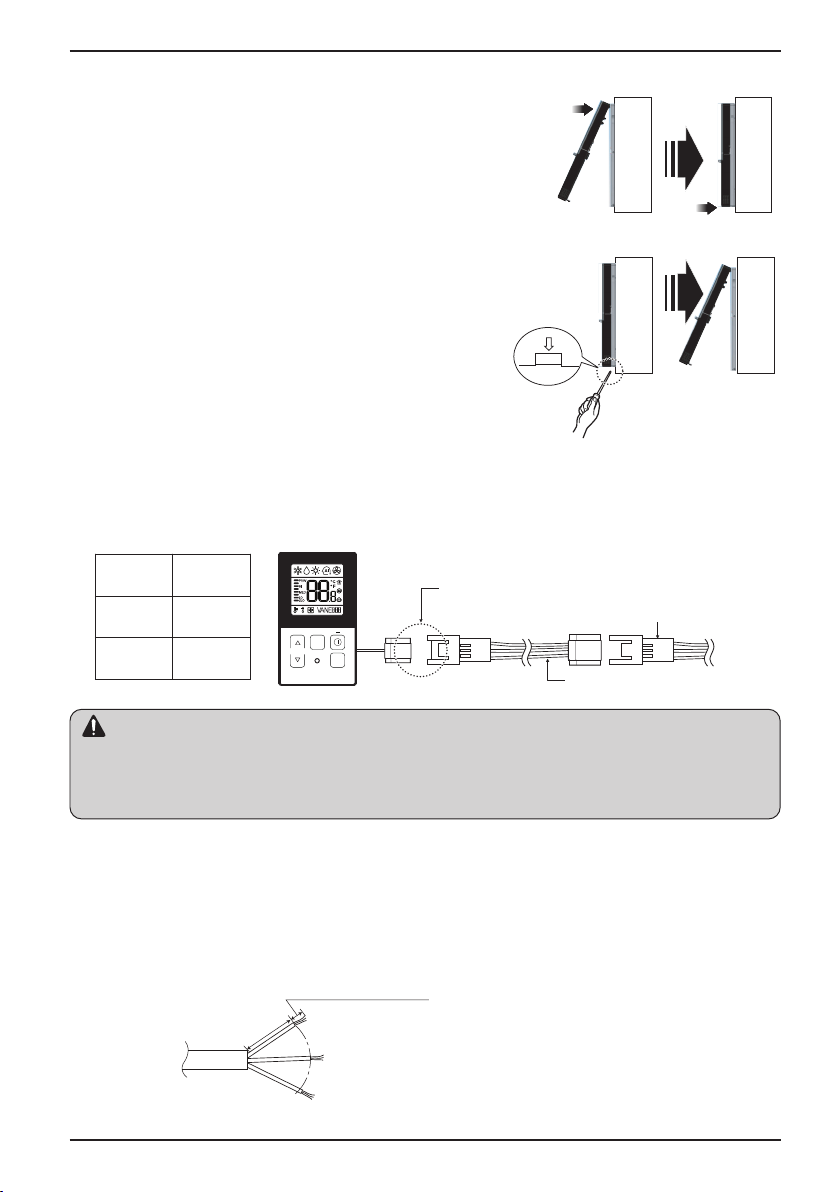
3. Please fix remote controller upper part into the
backplate attached to the surface of the wall, as
the picture below, and then, connect with
backplate by pressing lower part.
- Please make sure to leave no gaps on the top, bottom, left or right
sides between the remote controller and backplate.
- Before assembly with the backplate, arrange the Cable not to
interfere with circuit parts.
Remove remote controller by inserting a
screwdriver into the lower separating holes and
twisting to release the controller from backplate.
- There are two separating holes. Please individually separate one
at a time.
- Please be careful not to damage the inside
components when separating.
4. Please refer to the following directions when connecting the indoor unit and the
wired remote controller together.
1) Please connect the cables as shown in the figure below when connecting the plug type cable from the
indoor unit’s C/BOX and the housing type of the extension cable.
Signal Yellow
12V Red
GND Black
• Specification of LG supplied extension cable: AWG#22, 3 core shielded. (Model : PZCWRC1)
h Apply enclosed noncombustible conduit(metal raceway) totally or use FT-6 rated cable or above level in
case of local electric & building code that requires plenum (CMP) cable usage.
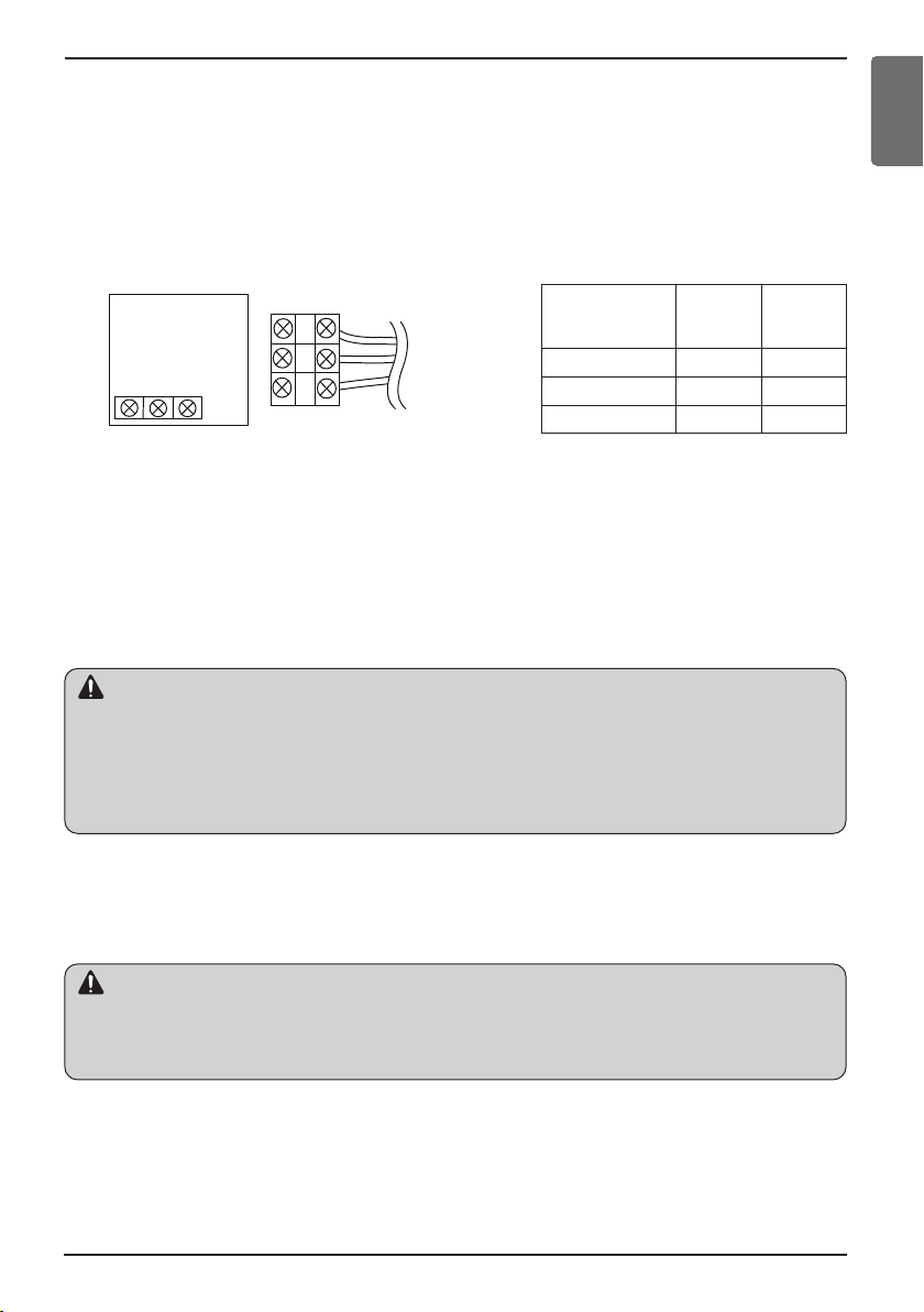
2) When connecting Terminal Blocks of the indoor C/BOX and the wired remote controller with the extension
cable, refer to the steps below.
①
Remove the screw on the cable which is fastened to the wired remote controller’s Terminal Block by
loosening with a screw driver.
②
Remove the housing of the provided 32ft extension cable with a cutting nipper and peel it as shown in the
figure below. (when purchasing the extension cable at the site directly, please peel it as shown in the figure
below.)
6 Wired Remote Controller
0.394 inch(10mm) ± 0.118 inch(3mm)
1.378 inch(35mm)
±0.197 inch(5mm)
Page 7
Installation instruction
CAUTION
CAUTION
YELLOW RED BLACK
Signal 12V GND
Remote
controller PCB
Indoor unit
side
③
Make sure each wire is securely fastened under each screw terminal and the wires are not in contact with
each other.
④
Please connect the Terminal blocks of indoor unit’s C/BOX and wired remote controller by referring to the
images and contents shown below.
Connect the yellow(signal) part of the wired remote controller’s terminal block and the ‘YL’ part of the indoor
unit’s terminal block.
Connect the red(12V) part of the wired remote controller’s terminal block and the ‘RD’ part of the indoor
unit’s terminal block.
Connect the black(GND) part of the wired remote controller’s terminal block and the ‘BK’ part of the indoor
unit’s terminal block.
Remote controller
PCB Terminal
block Remark
YELLOW YL Signal
RED RD 12V
BLACK BK GND
<Remote controller> <Indoor Terminal Block>
h In case of loosened screws or insufficient contact between the terminal and the wire, remote controller
may not function properly.
h When the power is off on the remote controller, check the connection between the remote controller and
Terminal Block.
h Use an appropriate screwdriver for tightening the terminal screws. A screwdriver with a small head will
strip the head and make proper tightening impossible.
h Over-tightening the terminal screws may break wires and terminal block structure.
Indoor
Terminal
block
Function
ENGLISH
• Installation work must be performed in accordance with the national wiring standards and local by
authorized personnel only.
• Installations must comply with the applicable local/national or international standards.
• AWG#22, 3 core shielded is recommended when using the large hole in the center of the back plate.
• AWG#24, 3 core shielded is recommended when using the side or top knock-out of the back plate.
5. Please use an extension cable if the distance between the wired remote controller
and the indoor unit is longer than 32ft(10m).
When installing the wired remote controller, do not bury it in the wall.
(It can cause damage in the temperature sensor.)
Do not install the cable to be 164ft(50m) or longer. (It can cause communication error.)
Owner’s & Installation Manual 7
Page 8
Installation instruction
Remote controller installation
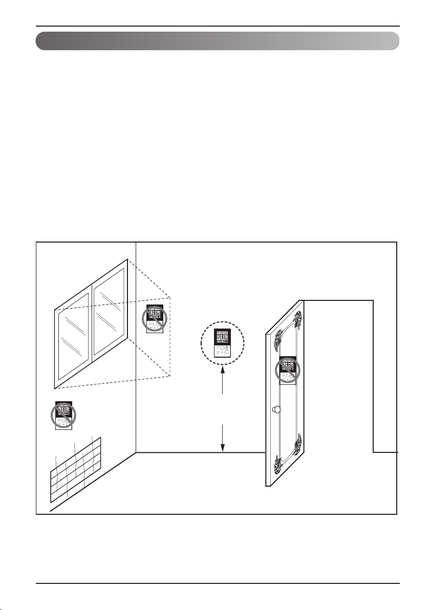
Since the room temperature sensor is in the remote controller, the remote controller box
should be installed in a place away from direct sunlight, high humidity and direct supply of
cold air to maintain proper space temperature. Install the remote controller about 5ft(1.5m)
above the floor in an area with good air circulation at an average temperature.
Do not install the remote controller where it can be affected by:
- Drafts, or dead spots behind doors and in corners.
- Hot or cold air from ducts.
- Radiant heat from sun or appliances.
- Concealed pipes and chimneys.
- Uncontrolled areas such as an outside wall behind the remote controller.
- This remote controller is equipped with LCD display. For proper display of the remote
controller LCD's, the remote controller should be installed properly as shown in Fig.1.
(The standard height is 4~5 ft (1.2~1.5 m) from floor level.)
Direct
Sun ray contact area
TEMP
no
FAN
SPEED
TEMP
OPER
MODE
no
8 Wired Remote Controller
FAN
SPEED
OPER
MODE
yes
SPEED
TEMP
FAN
OPER
MODE
FAN
SPEED
TEMP
OPER
MODE
no
5feet
(1.5meters)
(Fig. 1)
Page 9
Installation instruction
GND
GND
12V
Signal wire
Signal wire
TEMP
FAN
SPEED
OPER
MODE
GND
12V
B Y R B Y R
MASTER SLAVE
Signal wire
GND
12V
Signal wire
TEMP
FAN
SPEED
OPER
MODE
TEMP
FAN
SPEED
OPER
MODE
ENGLISH
Group control
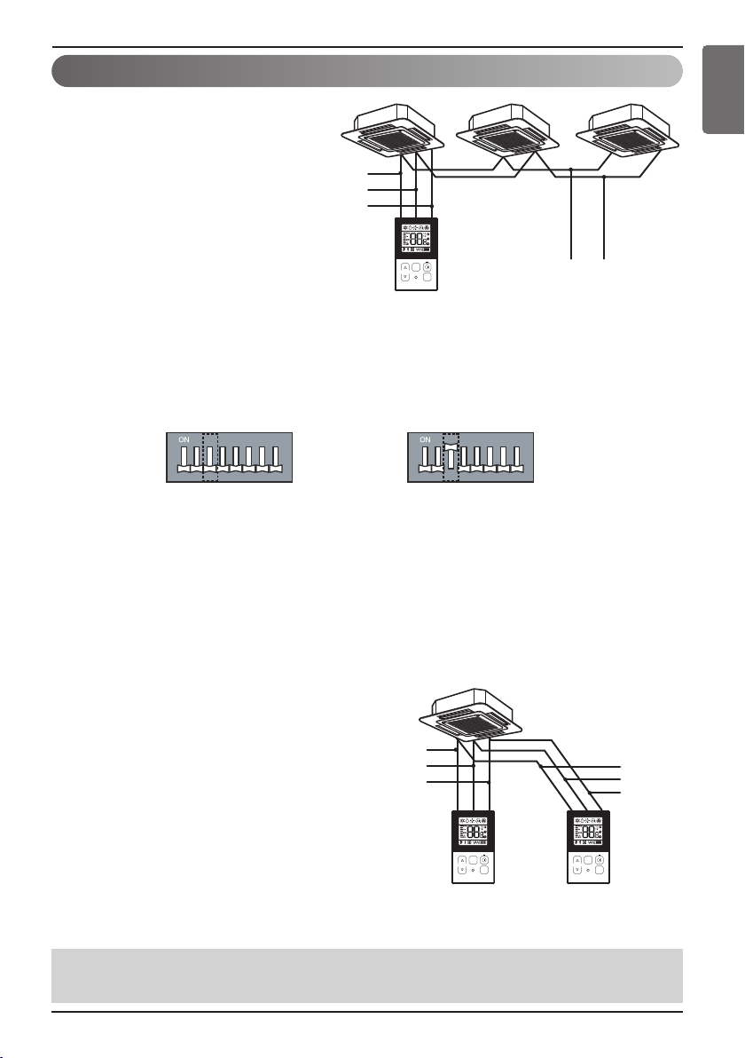
1. When installing more than 2
units of air conditioner to one
wired remote controller, please
connect as the right figure.
• If it is not event communication
indoor unit, set the unit as slave.
• Check for event communication
through the product manual.
When controlling multiple indoor units with event communication function with one remote
controller, you must change the master/slave setting from the indoor unit.
Indoor units, the master/slave configuration of the product after completion of indoor unit power
‘OFF’ and then ‘ON’ the power after 1 minutes elapsed sign up.
- For ceiling type cassette and duct product group, change the switch setting of the indoor PCB.
123456 78 12345678
#3 switch OFF: Master
#3 switch ON: Slave
(Factory default setting)
- For wall-mount type and stand type product, change the master/slave setting with the wireless
remote controller. (Refer to wireless remote controller manual for detail)
h When installing 2 remote controllers to one indoor unit with event communication function, set
the master/slave of the remote controller. (Refer to remote controller master/slave selection)
When controlling the group, some functions excluding basic operation setting, fan level
Min/Mid/Max, remote controller lock setting and time setting may be limited.
2. When installing more than 2 wired
remote controllers to one air
conditioner, please connect as the
right picture.
• When installing more than 2 units of wired
remote controller to one air conditioner, set
one wired remote controller as master and
the others all as slaves, as shown in the
right picture.
• You cannot control the group as shown in
the right for some products.
•
Refer to the product manual for more detail.
• When controlling in groups, set the master/slave of the remote controller. Refer to Installer
<When simultaneously connecting
2 sets of wired remote controller>
setting section on how to set master/slave for more detail.
Owner’s & Installation Manual 9
Page 10
Installation instruction
CAUTION
Installer Setting - How to enter installer setting mode
Installer setting mode is to set the detail function of the remote controller.
If the installer setting mode is not set correctly, it can cause problems to the product, user injury or property
damage. This must be set by an certificated installer, and any installation or change that is carried out by a
non-certificated person should be responsible for the results. In this case, free service cannot be provided.
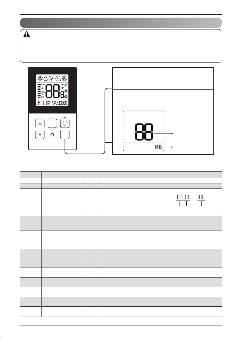
If you want to set installer setting mode, press
1
the temperature up button and the oper mode
button same time for five seconds.
When you enter the setting mode initially.
2
Function code is displayed on the LCD screen.
FAN
SPEED
TEMP
<Installer Setting Code Table>
1) General air-conditioner product
No. Function Code Value
1 Test Run 01 01:Set
2 Address Setting 02 00~FF : Address
3 E.S.P. Value 03
4 Thermistor 04 02:Indoor
5 Ceiling Height 05
6 Static Pressure 06
7 Master Setting 07
8
Fahrenheit Switching 01:Fahrenheit
9 Celsius Control 17
10
11
j Some contents may not be displayed depending on the product function
10 Wired Remote Controller
OPER
MODE
<ESP Step> <ESP Value> <Example>
01:VeryLow 0 ~ 255
02:Low
03:Med
04:High
05:Very High
01:Remo
03:2TH
01:Med
02:Low
03:High
04:Very High
01:V-H
02:F-H
03:V-L
04:F-L
00:Slave
Celsius
Refrigerant
Leak Detector 01 : Installed
Static Pressure
Step 01~ 11: static pressure step (code 32) set value
12
29
32
01:Master
00:Celsius
00 : 1 °C Control
01 : 0.5 °C Control
00 : Not installed
00: use static pressure (code 06) set value
(Optimized only for U.S.A)
Function Code ESP valueESP step
Function Code
Value
Page 11
<Installer Setting Code Table>
1) General air-conditioner product
No. Function Code Value
00: Not use
01: Simple operation On/Off
02: Simple dry contact (It takes HL when operation is off.)
03: Indoor unit single emergency stop
04: Occupied / unoccupied
12 CN_EXT setting 52
13 Auto ESP 68
05: Indoor unit all emergency stop
※It can be set only when there is indoor unit emergency stop
function.
06: Window contact
※It can be set only when there is window contact function.
07: Window contact lock
※It can be set only when there is window contact lock function.
0: Not use
1: Auto
200: Manual (190 V)
201: Manual (200 V)
202: Manual (210 V)
203: Manual (220 V)
204: Manual (230 V)
205: Manual (240 V)
206: Manual (250 V)
207: Manual (260 V)
208: Manual (270 V)
3: Pass
4: Fail
Installation instruction
ENGLISH
Owner’s & Installation Manual 11
Page 12
Installation instruction
Installer Setting - Test Run Mode
After installing the product, you must run a Test Run mode.
For details related to this operation, refer to the product manual.
When pressing the button and
1
button simultaneously for more than 3
seconds, the system will be entered
into the installer setting mode.
- After entering into the installer setting
mode, select the test run mode code
value by pressing the button.
* Test run mode code value : 01
OPER
MODE
OPER
MODE
When pressing the button, the test
2
operation mode will be performed, and it
OPER
MODE
is displayed as shown in the left figure.
TEMP
FAN
SPEED
OPER
MODE
When pressing the button and
3
button simultaneously for more than 3
seconds after the setting has been
completed, the setting mode will be
OPER
MODE
released.
- If there isn’t any button input for more
than 25 seconds, the installer setting
mode will also be released.
When approx. 18 minutes are elapsed
4
after starting of the test oper-mode, the
system will be stopped automatically
and converted to the standby state.
- If any button is inputted during the test
run mode, the test run mode will be
forced to be relreased.
• What is the test run mode??
- This means the operation of the product under the cooling, strong wind, and Comp on state
without performing room temperature control in order to confirm the installed state during the
product installation.
12 Wired Remote Controller
Page 13

Installation instruction
Installer Setting - Setting Address of Central Control
It's the function to use for connecting central control.
Please refer to central controller manual for the details
OPER
OPER
MODE
MODE
TEMP
FAN
SPEED
OPER
MODE
When pressing the button and
1
button simultaneously for more than 3
seconds, the system will be entered into the
installer setting mode.
-
After entering into the installer setting mode,
select the central control address setting
code value by pressing the button.
* Setting address of central control code
value : 02
Set up the group number and indoor unit with
2
the temperature adjustment(▲,▼) buttons.
TEMP
Group number
Indoor unit number
For example, when setting as
[ Group number=2 Indoor number=3 ]
it will be displayed as shown in the left figure.
ENGLISH
Press button to save the setting.
3
When pressing the button and
4
button simultaneously for more than 3
seconds after the setting has been
completed, the setting mode will be released.
- If there isn’t any button input for more than
25 seconds, the installer setting mode will
also be released.
• If you connect the indoor unit to the central controller, you should set the network address
of the indoor unit so that the central controller could recognize it.
• The center-control address is composed of the group number and the indoor-unit number.
Note : The remote controller displays 'HL' if central controller has locked the remote controller .
* In the case when the lock is set up at the central controller, ‘HL’ will be indicated on the display
window of the wired remote controller and the indoor unit will not be controlled by the remote
controller.
Owner’s & Installation Manual 13
OPER
MODE
Page 14

Installation instruction
Installer Setting - E.S.P.
This is the function that decides the strength of the wind for each wind level and because this
function is to make the installation easier.
• If you set ESP incorrectly, the air conditioner may malfunction.
• This setting must be carried out by a certificated-technician.
OPER
MODE
→
TEMP
FAN
SPEED
OPER
MODE
When pressing the button and
1
button simultaneously for more than 3
seconds, the system will be entered into
the installer setting mode.
- After entering into the installer setting
mode, select the E.S.P code value by
pressing the button.
* E.S.P code value : 03
Select the desired air flow rate with
2
3
FAN
SPEED
the button. Whenever pressing
FAN
the button, [SLO
SPEED
POW] will be indicated.
Select the desired air flow rate value
with the temperature up(▲), down(▼)
button.
* E.S.P value range : 0~255
E.S.P value will be indicated at the upper
right section of the display window.
OPER
MODE
→LO→
MED→HI
Press button to save the setting.
4
When pressing the button and
5
button simultaneously for more than 3
seconds after the setting has been
completed, the setting mode will be released.
- If there isn’t any button input for more
than 25 seconds, the installer setting
mode will also be released.
•
Precaution shall be taken not to alter the E.S.P value corresponded to each air flow section.
•
E.S.P value can be varied according to the products.
•
In the case of going to the next air flow rate stage by pressing the fan-speed button during the
setup of the E.S.P value, the E.S.P value of previous air flow rate will be maintained by
remembering the E.S.P value prior to the shift.
14 Wired Remote Controller
OPER
MODE
Page 15

Installation instruction
Installer Setting - Thermistor
This is the function to select the temperature sensor to judge the room temperature.
When pressing the button and
1
button simultaneously for more than 3
seconds, the system will be entered into
the installer setting mode.
- After entering into the installer setting
mode, select the thermistor sensor
setting code value by pressing the
button.
* Thermistor sensor selection code
value : 04
Select the desired setting value with the
2
FAN
SPEED
TEMP
OPER
MODE
temperature up(▲), down(▼) button.
*Setting value
01: Remote
controller
Code value
Val ue
02: Indoor unit
03: 2TH
OPER
MODE
OPER
MODE
ENGLISH
Press button to save the setting.
3
OPER
When pressing the button and
4
button simultaneously for more than 3
seconds after the setting has been
completed, the setting mode will be
released.
- If there isn’t any button input for more
than 25 seconds, the installer setting
mode will also be released.
• As the characteristic of the ‘2TH’ function can be different in accordance with the
products, refer to the product instruction manual for its detail.
Owner’s & Installation Manual 15
MODE
Page 16

Installation instruction
Installer Setting - Ceiling Height Selection
This function is to adjust FAN Airflow rate according to ceiling height (For ceiling type product)
OPER
OPER
MODE
MODE
When pressing the button and
1
button simultaneously for more than 3
seconds, the system will be entered into
the installer setting mode.
- After entering into the installer setting
mode, select the ceiling height setting
code value by pressing the button.
* Ceiling height setting code value : 05
Select the desired setting value with the
2
temperature up(▲), down(▼) button.
*Setting value
01: Low
02: Standard
03: High
04: Very high
TEMP
FAN
SPEED
OPER
MODE
Code value
Val ue
Press button to save the setting.
3
OPER
When pressing the button and
4
button simultaneously for more than 3
seconds after the setting has been
• As the ceiling height setting standard can
be different in accordance with the
products, refer to the product instruction
manual for its detail.
completed, the setting mode will be released.
- If there isn’t any button input for more
than 25 seconds, the installer setting
mode will also be released.
<Ceiling Height Selection Table>
Ceiling Height Level Description
01 Low Decrease the indoor airflow rate 1 step from standard level
02 Standard Set the indoor airflow rate as standard level
03 High Increase indoor airflow rate 1 step from standard level
04 Very high Increase indoor airflow rate 2 steps from standard level
MODE
• Ceiling height setting is available only for some products.
• Ceiling height of ‘Very high’ function may not exist depending on the indoor unit.
• Refer to the product manual for more details.
16 Wired Remote Controller
Page 17

Installation instruction
TEMP
FAN
SPEED
OPER
MODE
When pressing the button and
button simultaneously for more than 3
seconds, the system will be entered into
the installer setting mode.
-
After entering into the installer setting mode,
select the static pressure setting code value
by pressing the button.
* Static pressure setting code value : 06
1
Select the desired setting value with the
temperature up(▲), down(▼) button.
2
When pressing the button and
button simultaneously for more than 3
seconds after the setting has been
completed, the setting mode will be released.
- If there isn’t any button input for more than
25 seconds, the installer setting mode will
also be released.
4
OPER
MODE
OPER
MODE
Code value
*Setting value
01:V-H
02:F-H
03:V-L
04:F-L
Press button to save the setting.
3
OPER
MODE
Val ue
Installer Setting - Static Pressure Setting
This function is applied to only duct type. Setting this in other cases will cause malfunction.
ENGLISH
<Static Pressure Setting Table>
Pressure selection
01 V-H Variable High
02 F-H Fixed High
03 V-L Variable Low
04 F-L Fixed Low
Zone state ESP standard value
Function
Owner’s & Installation Manual 17
Page 18

Installation instruction
TEMP
FAN
SPEED
OPER
MODE
When pressing the button and
button simultaneously for more than 3
seconds, the system will be entered into the
installer setting mode.
-
After entering into the installer setting mode,
select the remote controller master / slave
setting code value by pressing the button.
* Remote controller master/slave setting
code value : 07
1
Select the desired setting value with the
temperature up(▲), down(▼) button.
2
When pressing the button and
button simultaneously for more than 3
seconds after the setting has been
completed, the setting mode will be released.
- If there isn’t any button input for more than
25 seconds, the installer setting mode will
also be released.
4
OPER
MODE
OPER
MODE
Code value
*Setting value
00:Slave
01:Master
OPER
MODE
Val ue
Press button to save the setting.
3
Installer Setting - Remote Controller Master/Slave Setup
It is a function for settings in group control, or 2-remote controller control.
Remote controller Function
Master
Slave
h Refer to the 'group control' part for details
Indoor unit operates based on master remote controller at group control.
(Master is set when delivering from the warehouse.)
Setup all remote controllers except one master remote controller to slave at
group control
• When controlling in groups, basic operation settings, airflow strength weak/medium/strong,
lock setting of the remote controller, time settings, and other functions may be restricted.
18 Wired Remote Controller
Page 19

Installation instruction
Installer Setting - Celsius / Fahrenheit Switching
This function is used for switching the display between Celsius and Fahrenheit.
(Optimized only for U.S.A)
When pressing the button and
1
button simultaneously for more than 3
seconds, the system will be entered into the
installer setting mode.
-
After entering into the installer setting mode,
select the Celsius / Fahrenheit setting code
value by pressing the button.
* Celsius/Fahrenheit setting code value : 12
Select the desired setting value with the
2
temperature up(▲), down(▼) button.
OPER
MODE
OPER
MODE
ENGLISH
*Setting value
00:Celsius
01:Fahrenheit
TEMP
FAN
SPEED
OPER
MODE
Code value
Val ue
Press button to save the setting.
3
OPER
When pressing the button and
4
button simultaneously for more than 3
seconds after the setting has been
completed, the setting mode will be released.
- If there isn’t any button input for more than
25 seconds, the installer setting mode will
also be released.
• Whenever press temp up(s), down(t) button in Fahrenheit mode, the temperature will
increase/drop 2 or 1 degrees.
MODE
Owner’s & Installation Manual 19
Page 20

Installation instruction
Installer Setting - Celsius Control Setting
This function is to set the unit for temperature control by 1°C or 0.5°C.
When pressing the button and
1
button simultaneously for more than 3
seconds, the system will be entered into the
installer setting mode.
-
After entering into the installer setting mode,
select the celsius control setting code value by
pressing the button.
OPER
MODE
* Celsius control setting code value : 17
Select the desired setting value with the
2
temperature up(▲), down(▼) button.
FAN
SPEED
TEMP
OPER
MODE
Code value
Val ue
Press button to save the setting.
3
OPER
MODE
* Setting value
00 : 1 °C Control
01 : 0.5 °C Control
20 Wired Remote Controller
OPER
When pressing the button and
4
button simultaneously for more than 3
MODE
seconds after the setting has been
completed, the setting mode will be released.
- If there isn’t any button input for more than
25 seconds, the installer setting mode will
also be released.
Page 21

Installation instruction
ENGLISH
Installer Setting - Setting for Refrigerant Leak Detector
This function is used when a refrigerant leak detector is additionally installed in the indoor unit or the
installed detector is removed.
OPER
OPER
MODE
MODE
When pressing the button and
1
button simultaneously for more than 3
seconds, the system will be entered into the
installer setting mode.
-
After entering into the installer setting mode,
select the Refrigerant Leak Detector setting
code value by pressing the button.
*
Refrigerant Leak Detector setting code value : 29
Select the desired setting value with the
2
temperature up(▲), down(▼) button.
TEMP
FAN
SPEED
OPER
MODE
*Setting value
00 : Not installed
Code value
Val ue
01 : Installed
Press button to save the setting.
3
OPER
When pressing the button and
4
button simultaneously for more than 3
seconds after the setting has been
completed, the setting mode will be released.
- If there isn’t any button input for more than
25 seconds, the installer setting mode will
also be released.
MODE
Owner’s & Installation Manual 21
Page 22

Installation instruction
Installer Setting - Static Pressure Step Setting
This function is applied to only duct type. Setting this in other cases will cause malfunction.
This function is only available on some models.
This is the function that static pressure of the product is divided in 11 steps for setting.
OPER
MODE
TEMP
FAN
SPEED
OPER
MODE
When pressing the button and
1
button simultaneously for more than 3
seconds, the system will be entered into
the installer setting mode.
-
After entering into the installer setting
mode, select the static pressure step
setting code value by pressing the
OPER
MODE
button.
* Static pressure step setting code value : 32
Select the desired setting value with the
2
temperature up(▲), down(▼) button.
Code value
Val ue
00: use static pressure (code 06) set value
01~ 11: static pressure step (code 32) set
value
Press button to save the setting.
3
OPER
When pressing the button and
4
button simultaneously for more than 3
seconds after the setting has been
completed, the setting mode will be released.
- If there isn’t any button input for more than
25 seconds, the installer setting mode will
also be released.
• Static Pressure (Code 06) setting will not be used if Static Pressure Step (Code 32) setting is being used.
• For the static pressure value for each step, refer to the indoor unit in the product manual.
22 Wired Remote Controller
MODE
Page 23

Installation instruction
Installer Setting – CN_EXT setting
It is the function to set to control the external input and output according to DI/DO set by the
customer using the indoor unit’s Dry Contact Port. (It is the function to decide the usage of the
contact point port (CN_EXT) mounted in the indoor unit PCB.)
OPER
When pressing the button and
1
button simultaneously for more than 3
MODE
seconds, the system will be entered into
the installer setting mode.
OPER
-
If button is pressed repeatedly, it is
MODE
moved to CN_EXT setting menu as the
picture below.
*
Code value : 52
Select the desired setting value with the
2
temperature up(▲), down(▼) button.
FAN
SPEED
TEMP
OPER
MODE
Code value
Val ue
Press button to save the setting.
3
ENGLISH
Value
00
01
02
03
04
05
06
07
When pressing the button and
4
button simultaneously for more than 3
seconds after the setting has been
completed, the setting mode will be released.
- If there isn’t any button input for more than
25 seconds, the installer setting mode will
also be released.
Description
Not use
Simple operation On/Off
Simple dry contact (It takes HL when operation is off.)
Indoor unit single emergency stop
Occupied / unoccupied
Indoor unit all emergency stop
※It can be set only when there is indoor unit emergency stop function.
Window contact
※It can be set only when there is window contact function.
Window contact lock
※It can be set only when there is window contact lock function.
Owner’s & Installation Manual 23
OPER
MODE
Page 24

Installation instruction
Installer Setting - Auto ESP
This function automatically sets the rotation speed of the fans corresponding to each step of rated
airflow for easy installation.
OPER
MODE
TEMP
FAN
SPEED
OPER
MODE
When pressing the button and
1
button simultaneously for more than 3
seconds, the system will be entered into
the installer setting mode.
OPER
-
If button is pressed repeatedly, it is
MODE
moved to Auto ESP setting menu as the
picture below.
*
Code value : 68
Set the auto ESP mode using the
2
Temperature button and set the manual
step using the Fan speed button.
Function code
Value 1 : Auto ESP mode
Value 2 : Manual step
Press button to save the setting.
3
24 Wired Remote Controller
OPER
When pressing the button and
4
button simultaneously for more than 3
seconds after the setting has been
completed, the setting mode will be released.
- If there isn’t any button input for more than
25 seconds, the installer setting mode will
also be released.
MODE
Page 25

Installation instruction
※ The voltage can be set by setting the Auto ESP Mode to 'Manual (2)', then pressing the
`Fanspeed` button.
※ While 'Auto ESP' is being set, the display on the wired remote control changes as shown below,
and the wired remote control cannot be operated.
※ Once the set-up is complete, you can enter installer setup (68) to check whether the set-up has
succeeded or failed. (3: Success, 4: Failure)
ENGLISH
Value 1
(Auto ESP mode)
0
(Not use)
1
(Auto)
2
(Manual)
3-
4-
Value 2
(Manual Step)
--
--
00 190 V
01 200 V
02 210 V
03 220 V
04 230 V
05 240 V
06 250 V
07 260 V
08 270 V
Description
(Voltage setting)
Cannot be set, only monitoring is possible.
If the value1 is 3, setting is successful.
Cannot be set, only monitoring is possible.
If the value1 is 4, setting has failed.
Owner’s & Installation Manual 25
Page 26

Owner's instruction
Owner's instruction
Standard Operation - Cooling Mode
It cools the room by comfortable and clean wind.
Cooling operation will begin if you press
1
the button.
Press the temperature button and set the
2
desired room temperature lower than the
current room temperature.
TEMP
-
Setting temp range : 18°C~30°C (64°F~86°F)
FAN
SPEED
TEMP
OPER
MODE
- If the desired temperature is set higher than
the current room temperature, the cooling
function will not begin and just the blowing
operation will continue.
If you prees the mode button during the
3
operation, the operation mode will be
changed in the order of cooling,
dry(dehumidification),heating,auto-operation
and fan operation. If the product is a
cooling-only model, the operation mode will
be changed in the order of cooling,
dry(dehumidification), auto-operation and fan
operation.
A click of the button will increase the
desired temperature by 1°C.
A click of the button will decrease the
desired temperature by 1°C.
26 Wired Remote Controller
If you press the button, the cooling
4
operation will stop.
Page 27

Standard Operation - Heating Mode
It supplies warm wind to the indoor
If you want to set the heating operation,
1
press the button. And press the
button.
Set the desired room temperature higher
2
than the current room temperature.
TEMP
-
Setting temp range : 16°C~30°C (60°F~86°F)
FAN
SPEED
TEMP
OPER
MODE
- If the desired temperature is set lower than
the current room temperature, the heating
function will not begin.
If you prees the mode button during the
3
operation, the operation mode will be
changed in the order of cooling,
dry(dehumidification),heating,auto-operation
and fan operation.
Owner's instruction
OPER
MODE
A click of the button will increase the
desired temperature by 1°C.
A click of the button will decrease the
desired temperature by 1°C.
ENGLISH
If you press the button, the cooling
4
operation will stop.
What is the three-minute delay function?
It will take time for the product to blow warm air. The delay is to protect the compressor.
The room will be heated with warm air after three minutes when the compressor begins
operation.
n The cooling-only model will not do heating function.
Owner’s & Installation Manual 27
Page 28

Owner's instruction
Standard Operation - Auto Operation Mode
After operating the product by pressing
1
TEMP
FAN
SPEED
OPER
MODE
the button, set up the auto operation
by pressing the button.
“Auto Change Over Mode” – Heat pump model only
2
When desired the set temperature is higher than the
room temperature during the auto operation
=> Heating operation
[For Heat pump models only]
When desired the set temperature is lower than the
room temperature during the auto operation
=> Cooling operation
- Setting temp range : 18°C~30°C (64°F~86°F)
“Auto Operation Mode”
3
For the products with the exclusive purpose
of cooling only, “AI” is indicated at the
temperature display section.
OPER
MODE
28 Wired Remote Controller
When cold
When cool
When appropriate
When warm
When hot
Page 29

Standard Operation - Dehumidification Mode
It removes humidity while air-cooling weakly.
After operating the product by pressing
1
the button, set up the dry
(Dehumidification) by pressing the
button.
When the dry operation is selected, “dH” will
2
be shown on the display window as shown
on the left side.
- The temperature setting can not be
adjusted during operation this mode.
FAN
SPEED
TEMP
FAN
SPEED
OPER
MODE
Press the button to select airflow rate
3
[SLO→LO→MED→HI].
- The initial wind powerfulness of humidity
removal drive is ‘weak’.
Owner's instruction
OPER
MODE
ENGLISH
• In rainy season or high humidity climate, it is possible to operate simultaneously dehumidifier and
cooling mode to remove humidity effectively.
• The menu item of wind powerfulness might not be partially selected according to the product.
Owner’s & Installation Manual 29
Page 30

Owner's instruction
Standard Operation - Fan Mode
It blows the air as it is in the indoor, not the cold wind.
After operating the product by pressing
1
the button, set up the fan operation by
pressing the button.
When the dry operation is selected, “Fn” will
2
be shown on the display window as shown
on the left side.
- The temperature setting can not be
adjusted during operation this mode.
Press the button to select airflow rate
3
FAN
SPEED
TEMP
OPER
MODE
[SLO→LO→MED→HI].
When running ventilation, compressor of
AHU doesn’t work.
FAN
SPEED
OPER
MODE
• Ventilation drive does not release cool wind but general fan.
• Because it releases the wind that has no temperature difference from the room, it functions to
circulate the inside air.
• The menu item of wind powerfulness might not be partially selected according to the product.
30 Wired Remote Controller
Page 31

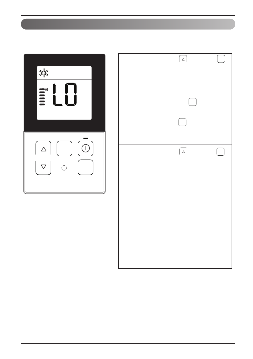
Function Setting - Fan Speed Selection
It blows the air as it is in the indoor, not the cold wind.
Select the proper fan speed which you want
1
by pressing the button on the remote
controller.
- If you press the button, the fan speed
will change in the order of [SLO→LO→MED
→HI→POW].
- The initial fan speed is “HI”.
- If the product is not compatible with the fan
speed control, it will not function as per
your selection.
Fan Speed Selection in Cooling Operation
FAN
SPEED
TEMP
OPER
MODE
FAN
SPEED
Owner's instruction
ENGLISH
Fan Speed Selection in Heating, Dry, Fan,
Auto-Operation
Owner’s & Installation Manual 31
Page 32

Owner's instruction
Function Setting - Room Temperature Check
FAN
SPEED
TEMP
FAN
SPEED
OPER
MODE
When pressing the button of the remote
1
controller adjustment section for approx. 3
seconds, the room temperature will be
indicated for about 5 seconds before
resuming to the previous display panel.
In the case of the room temperature display,
the room temperature can be different in
accordance with the setting of the remote
controller’s room temperature detection
selection.
* As the temperature distribution of the remote controller Installation space is not uniform,
slight difference can be generated between the actually felt temperature and the room
temperature indication of the remote controller.
32 Wired Remote Controller
Page 33

Function setting - Child Lock
TEMP
FAN
SPEED
OPER
MODE
During the operation, when pressing the
button and button for approx. 3 seconds,
the ‘Child Lock’ function can be used.
-
At the time of initial setting of the ‘Child Lock’,
the ‘CL’ will be indicated approx. 3 seconds
at the temperature display section before
resuming to the previous mode.
After the setting of the ‘CL’, if another button
is setup, the button can not be recognized as
the ‘CL’ is indicated at the temperature
display section for approx. 3 seconds.
1
If the ‘CL’ function is wanted to be used
under the operation standby state, press the
button and button for approx.
3 seconds under the standby mode state and
the system will be the ‘CL’ state.
2
As for the releasing method, when pressing
the button and button for approx. 3
seconds, the ‘CL’ function can be released.
3
FAN
SPEED
FAN
SPEED
FAN
SPEED
It is the function to use preventing children or others from careless using.
Owner's instruction
ENGLISH
Owner’s & Installation Manual 33
Page 34

Owner's instruction
TEMP
FAN
SPEED
OPER
MODE
During the operation, when pressing the
button and button for approx. 3 seconds,
the ‘Auto Swing’ function can be used.
1
During the operation of the ‘Auto Swing’
function, when pressing the button and
button simultaneously for approx. 3
seconds, the ‘Auto Swing’ function can be
released.
- This function is not indicated on the wired
remote controller even if the product is
actually operated.
- This function may not be performed in
accordance with the products.
2
OPER
MODE
OPER
MODE
Function setting - Auto Swing
This function is to adjust angle at which airflow is blow out.
34 Wired Remote Controller
Page 35

Function setting - Vane Angle Control
TEMP
FAN
SPEED
OPER
MODE
When pressing the button for approx. 3
seconds during the operation, the vane angle
control setting function can be used.
1
Initial ‘vane1’ is indicated at the window
panel upper section and the system
becomes the setting mode as ‘P0’ is
indicated at the temperature display section.
2
Select the vane angle number from ‘vane1’
to ‘vane4’ by pressing the button.
- When selecting the vane number, the vane
which is corresponded to the number will be
opened and closed.
3
Select the vane angle from ‘P0’ to ‘P6’ with
the temp up/down button.
- In the case of the wind flowing out angle,
(Minimum angle)…………….(Max angle)
‘ P0 < P1 < P2 < P3 < P4 < P5 < P6 ’
4
When pressing the button for 3 seconds,
the setting is finished and the vane angle
control setting is completed.
- If there isn’t any button input for approx. 60
seconds after the setting, the system will
be coming out of the vane angle control
setting mode automatically.
5
OPER
MODE
OPER
MODE
OPER
MODE
This function is to adjust angle at which airflow is blow out.
Owner's instruction
ENGLISH
* Vane number and the angle of wind can be selected differently in accordance with the
products.
Owner’s & Installation Manual 35
Page 36

Owner's instruction
Different mode drive
Different mode drive is a phenomenon taking place when indoor units' drive mode is different in the
case that a few indoor units are set up at one AHU.
(Different mode drive doesn't show up at cooling exclusive model.)
If one indoor unit operate heating mode while
1
several indoor units are operating cooling
mode, outdoor segment and cooling segment
are blinking like display on the left.
=> It means operation of cooling mode in
outdoor unit.
If one indoor unit operate cooling or
2
dehumidification mode while several indoor
units are operating heating mode, outdoor
segment and cooling segment are blinking.
=> It means operation of heating mode in
outdoor unit.
If pressing button, indoor unit
automatically runs at the mode that different
indoor units are running after about 5
seconds and operates.
TEMP
FAN
SPEED
OPER
MODE
3
• If the product is not compatible with the different mode operation, LCD will be displayed ‘CH07’.
• If ‘CH07’ is displayed, please change the mode.
• Different mode operation is not error.
36 Wired Remote Controller
Page 37

Owner's instruction
ENGLISH
WLAN(Wireless LAN) Module Access Point Mode
It is the function to operate WLAN (Wireless LAN) module connected to the product in access point
mode. This function is available for particular models to apply WLAN Module.
Refer to the installation manual of product whether available or not.
FAN
SPEED
TEMP
FAN
SPEED
OPER
MODE
During the operation, when pressing the
1
button and button for approx.
OPER
MODE
3 seconds, the ‘WLAN(Wireless LAN)
Module Access Point Mode’ function can be
used.
While WLAN module is operating in access
2
point mode, the term of 'AP' blinks on the
screen of wired remote controller.
- It will take approx. five seconds before
WLAN module operates in access point
mode.
- In the case WLAN module is not installed,
the access point mode does not work.
Owner’s & Installation Manual 37
Page 38

Owner's instruction
TEMP
FAN
SPEED
OPER
MODE
Self-diagnosis for Trouble Mode
It automatically runs a self-diagnosis when there is a
trouble detected in the system.
It displays the troble mode number with maintenance
CODE.
<Individual control>
<Group control>
h When detecting an error during group control, the system will
display as below.
<In case of CH05 error, these two characters CH and 05 are
alternatively displayed.>
In order to expedite a service, please remember the error
number and provide it when consulting an installer.
Outage Compensation Function
If power supply fails due to outage or other reasons, the outage compensation function automatically
retrieves the operating conditions previously programmed before the power failure. Thus, you don’t
need to press any buttons.
(Additional functions will not be retrieved automatically.)
38 Wired Remote Controller
Page 39

Owner's instruction
Checkups before reporting breakdown
Please first check the items below for product's defects before consulting to service center.
ENGLISH
Symptoms
• Is air-conditioner's power on?
It has no power
on.
It doesn't operate
reservation drive.
It doesn't release
cool wind.
Air-conditioner
automatically runs
or stops.
Error is indicated
on remote
controller
indication window.
• Are air-conditioner and remote
• Is cable connection correct?
• Did you correctly setup time?
• Did you correctly make a
• Is desired temperature setup
• Isn't reservation drive setup?
• Does remote controller indication
controller properly connected
with cable?
reservation?
lower than current temperature?
window indicate 'CH03'?
ManagementCheck-up
• Please check up circuit breaker.
• Please check up wire remote controller's
setup condition.
• Please connect air-conditioner and remote
controller cable.
• Please check again referring to setup
method at the manual.
• Please set up current time correctly.
• Please set up again referring to the
manual.
• Please set up desired temperature lower
than current temperature.
• Please cancel reservation drive.
• Please check again wire remote
controller's setup condition.
• Please check again connection condition
of air-conditioner and remote controller
cable.
Owner’s & Installation Manual 39
Page 40

40 Wired Remote Controller
 Loading...