

Page 1
LG
CNU
LG
IMPORTANT
• Please read this Installation Manual completely
before installing the product.
• Installation work must be performed in
accordance with the national wiring standards
by authorized personnel only.
• Please retain this Installation Manual for future
reference after reading it thoroughly.
Model: PQNFG14B0
INSTALLATION MANUAL
Visit us at : http://www.lgservice.com
ENGLISH ITALIANO ESPAÑOL FRANÇAIS DEUTSCH
Page 2

2 CNU
CNU
TABLE OF CONTENTS
■ Cautions for safety .................................................................................................3
■ Part Description ......................................................................................................6
Parts of a CNU..........................................................................................................6
CNU connection........................................................................................................7
■ Wiring Diagram ......................................................................................................8
Multi V SUPER(PLUS) & MPS PRODUCT...............................................................8
Connection................................................................................................................9
■ Network Interface Connection.............................................................................11
Dip Switch Configuration.........................................................................................11
■ CNU setup method................................................................................................12
Connect with the PC...............................................................................................12
Set the PC environment for CNU IP setting............................................................13
CNU Setup Configuration .......................................................................................18
■ CNU Normal operation condition confirmation .................................................19
Hardware operation condition confirmation ............................................................19
LAN communication condition confirmation ...........................................................19
485 Communication condition confirmation............................................................19
Page 3
Cautions for safety
Installation Manual 3
ENGLISH
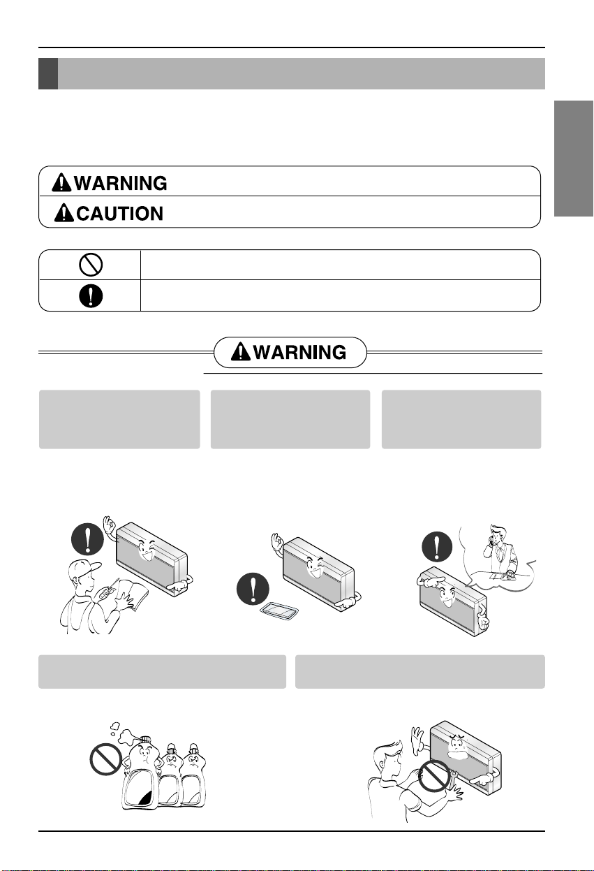
You should always request
product installation to our
Service Center or to
installation expert agency.
Use specified parts.
When reinstalling an existing
installed product, request it to
our Service Center or to
installation expert agency.
• Otherwise it may cause
fire hazard, electric shock,
explosion, injury or
damage.
• Or else it may cause fire
hazard, electric shock,
explosion, injury, damage
and trouble failure.
• Otherwise it may cause fire
hazard, electric shock,
explosion, injury or damage.
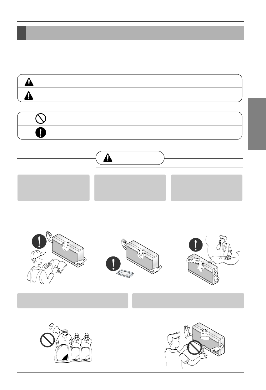
Don’t keep or use ignitable gas or any other
flammable material in vicinity of the product.
Don’t disassemble, repair and modify the
product at your will.
• Otherwise it may cause fire hazard and
product trouble failure.
• Or else it may cause fire hazard and electric
shock.
Cautions for safety
To prevent injury to the user or other people and property damage, the following instructions must be
followed.
■ Incorrect operation due to ignoring instruction will cause harm or damage. The seriousness is
classified by the following indications.
This symbol indicates the possibility of death or serious injury.
This symbol indicates the possibility of injury or damage to properties only.
■ Meanings of symbols used in this manual are as shown below.
Be sure not to do.
Be sure to follow the instruction.
■ WHEN INSTALLING
SPECIFIED
PARTS
Benzene
Ether
Thinner
Page 4
Cautions for safety
4 CNU
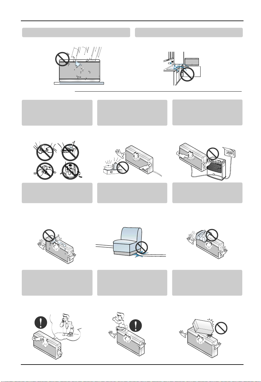
Don’t install it where rain falls on. Don’t install it in humid place.
• Otherwise it may cause product failure. • Otherwise it may cause product failure.
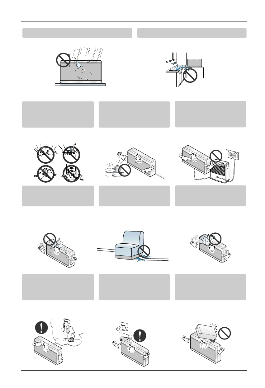
Don’t change or extend
electric supply wire at your
will.
Don’t let there exist fire heat
near the product.
Don’t use heat equipment
near the electricity supply
line.
• Or else it may cause fire
hazard and electric shock.
• Otherwise it may cause fire
hazard.
• Or else it may cause fire
hazard and electric shock.
Don’t spill water into interior
of the product.
Don’t put heavy material upon
electricity supply chord.
Don’t put heavy material
upon the product.
• Otherwise it may cause
electric shock and product
failure.
• Or else it may cause fire
hazard and electric shock.
• Or else it may cause
product trouble failure.
Always request to our Service
Center or installation expert agency
in such case as the product has
been submerged under water.
Child or the old and the weak
shall use it under custody of
patron.
Don’t give impact to the
product.
• Or else it may cause fire
hazard and electric shock.
• Otherwise it may cause
safety accident or product
failure.
• If the product is impacted,
it may cause product
trouble failure.
■ WHEN USING
Page 5
Cautions for safety
Installation Manual 5
ENGLISH
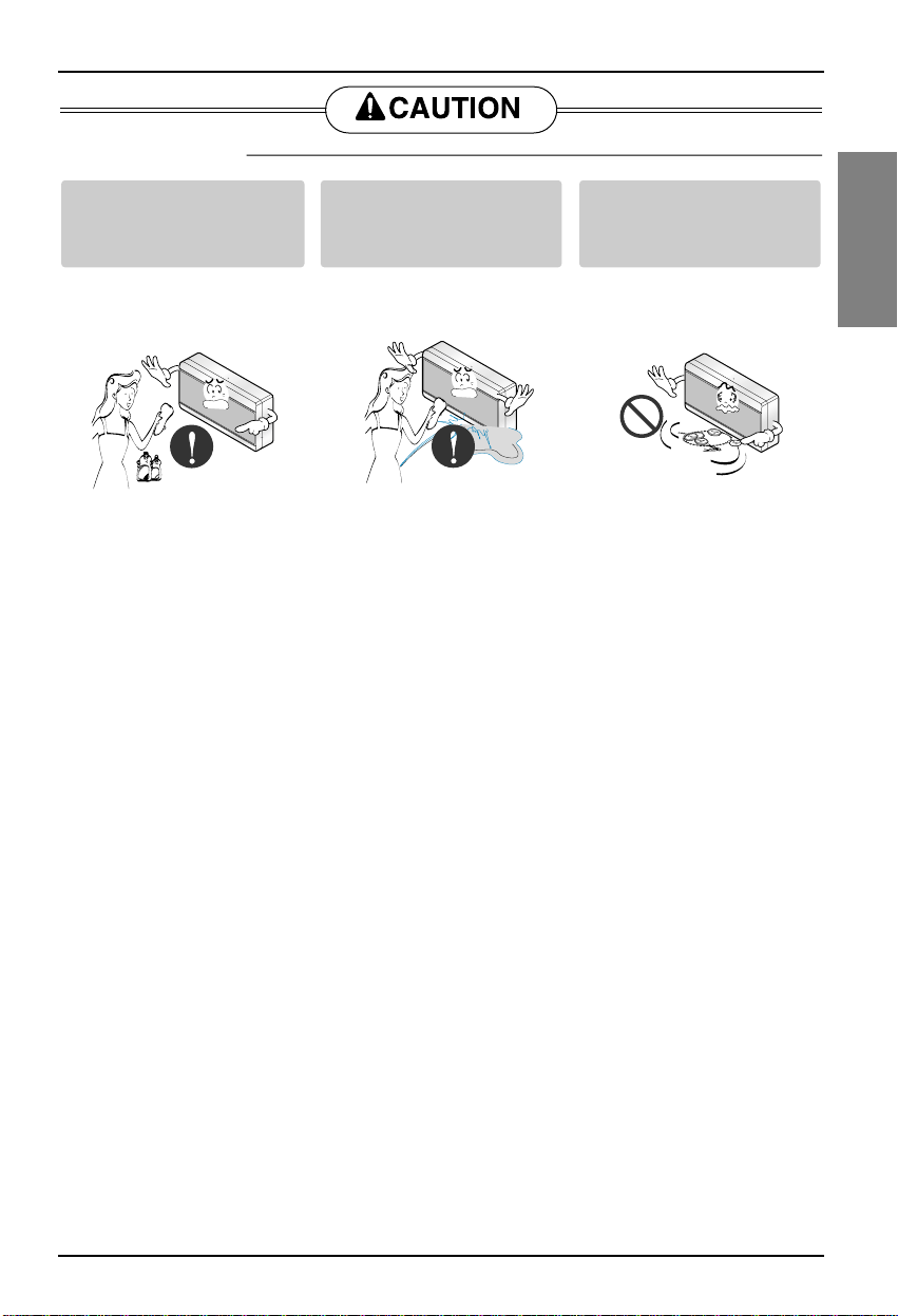
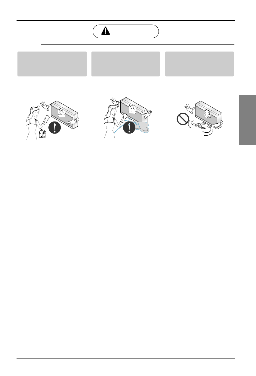
Don’t clean the product with
strong detergent of solvents
but only use soft cloth.
If water has been smeared
on electric charge part, use
it after removing water.
Don’t let metallic products
of necklace, coin, key, watch
etc. touch the battery
terminal.
• Or else it may cause fire
hazard and product
deformation.
• Or else it may cause
product failure.
• Or else it may cause product
failure and injury.
■ WHEN USING
W
a
x
Thinner
Page 6
Part Description
Part Description
6 CNU
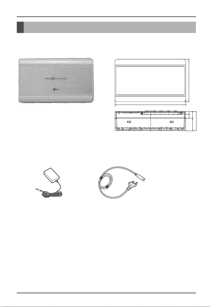
■ Parts of a CNU
CNU CONT BOX
LGAP
Dimension
200.0
Input voltage : DC9V 2.0A
In/out port : RS232 1ea
RS485 1ea
LAN 1ea
120.0
7.5
20.0
55.0
35.0
Power supply
DC 9V , 2.0A
International standard
IEC320 C8 type
Power cord
NOTE : AC input spec.
- 100~250 VAC universal input
- Desktop style or wall plug style
Page 7
Part Description
Installation Manual 7
ENGLISH
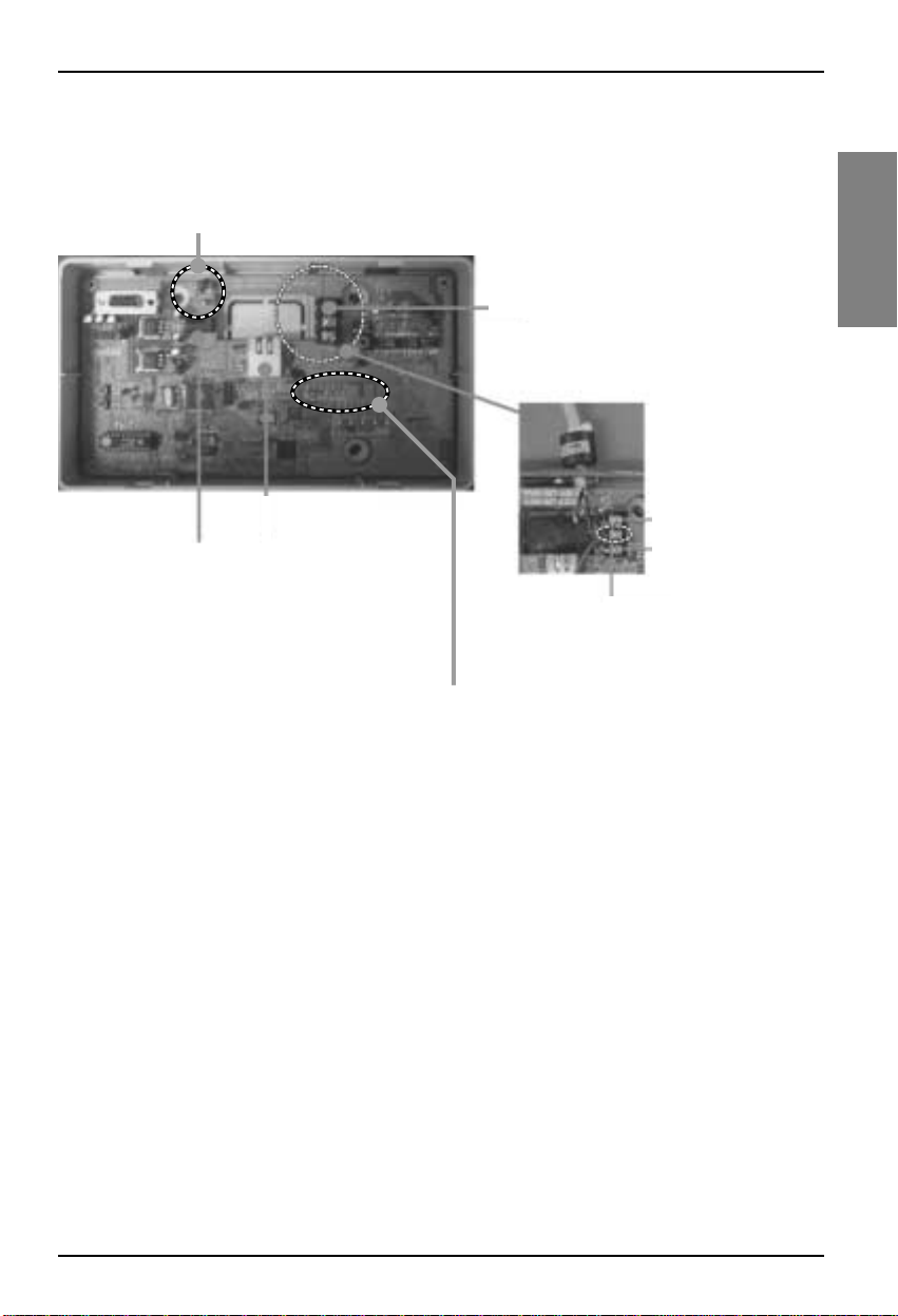
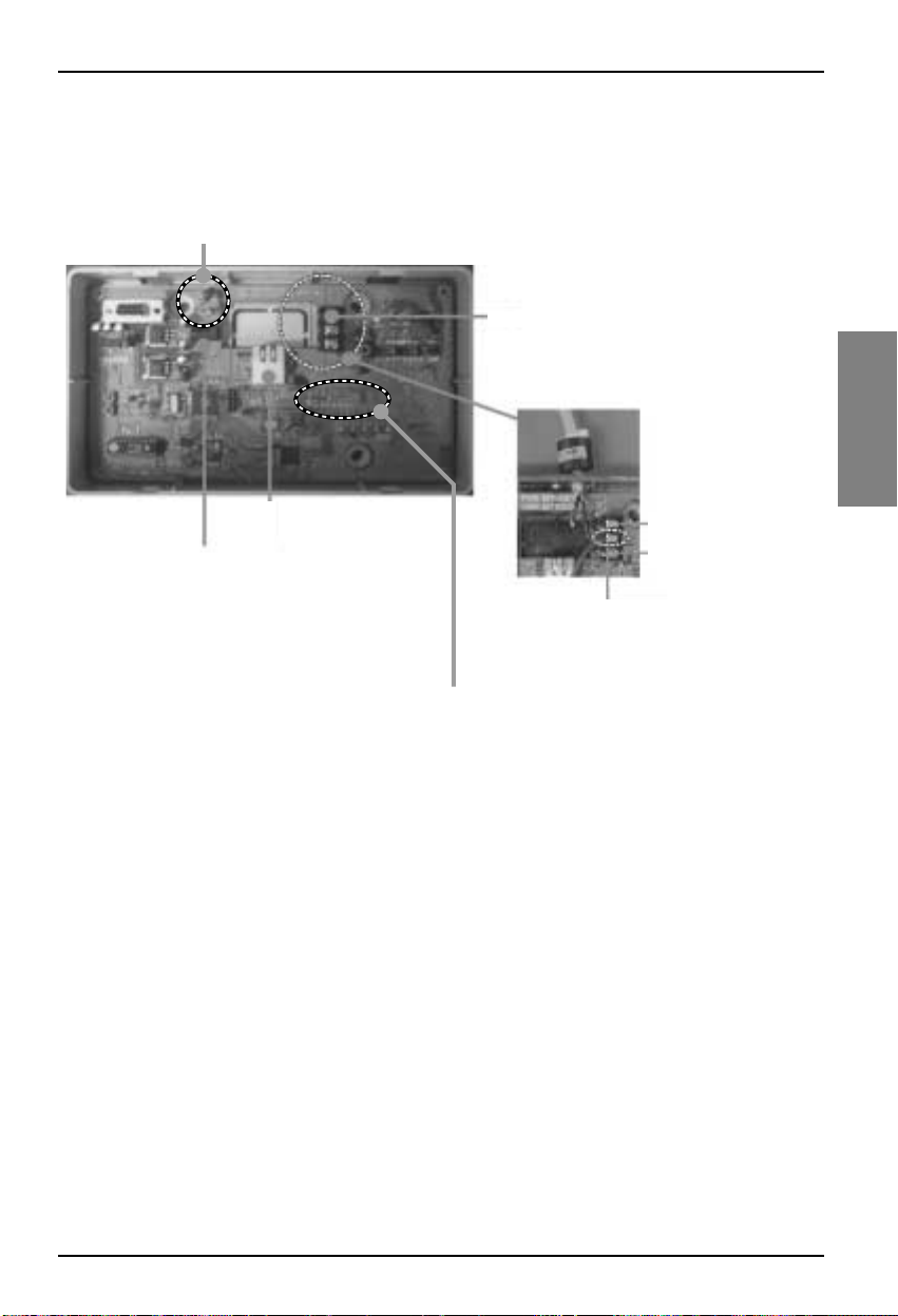
■ CNU connection
Reset button
Power Connector
DC 9V Adaptor
(supplied)
RS-485 Communication Terminal
Connect with PMNFP14A0 (PMNFP14A1) :
BUS_A, B
• Cautions while connecting RS-485
communication line : When connecting the 485
communication line do as the picture below
using the provided core and tie.
PQNFG14B0 ---PMNFP14A0
RJ45 Connector :
Connect with HUB OR
Deluxe/PC Central
Controller
• NOTICE
this terminal is for communication stability
so, don’t remove and connect other line
L06D: Connection of LAN H/W (LINK LED)
L07D: Connection of LAN H/W LED(DUPLEX)
L08D: 10MEGA BASE Communication LED
(when CNU II is connected with Deluxe central controller)
L09D: 100MEGA BASE Communication LED
(when CNU II is connected with PC central controller)
L10D: COLLISION DETECTOR LED
(PMNFP14A1)
BUS_A ---- BUS_A
BUS_B ---- BUS_B
Page 8
Wiring Diagram
8 CNU
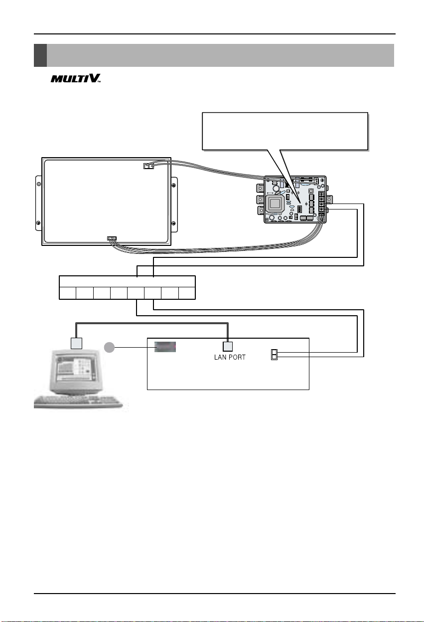
ON
L1 2 3 4
KSDO4H
CNU PCB
BUS_A
BUS_A
BUS_B
BUS_B
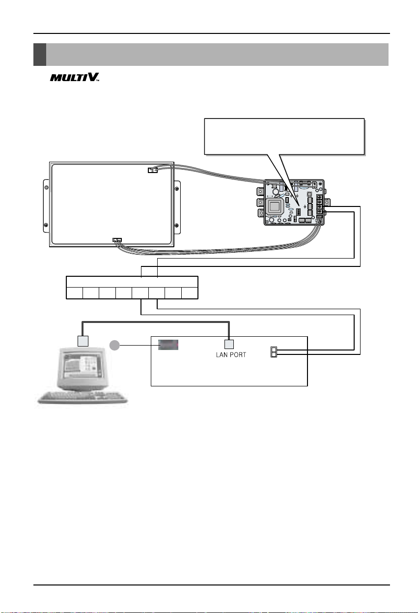
CNU Connection
DC 9V adaptor connection
PC Central controller
MULTI V OUTDOOR TERMINAL BLOCK
DC 9V
ABEFCD
VCC GND
CN_CENTRAL
Multi-V SUPER
(PLUS) or MPS product
Outdoor main PCB
Please refer to network interface setting method on
the 11 page.
It explains about how to set PI 485(M) dip switch.
■ SUPER(PLUS) & MPS PRODUCT
Wiring Diagram
❈ NOTICE : Use of terminal block in case of Multi V and other models may or may not be needed.
If it is not present, make direct connections.
Page 9
Wiring Diagram
Installation Manual 9
ENGLISH
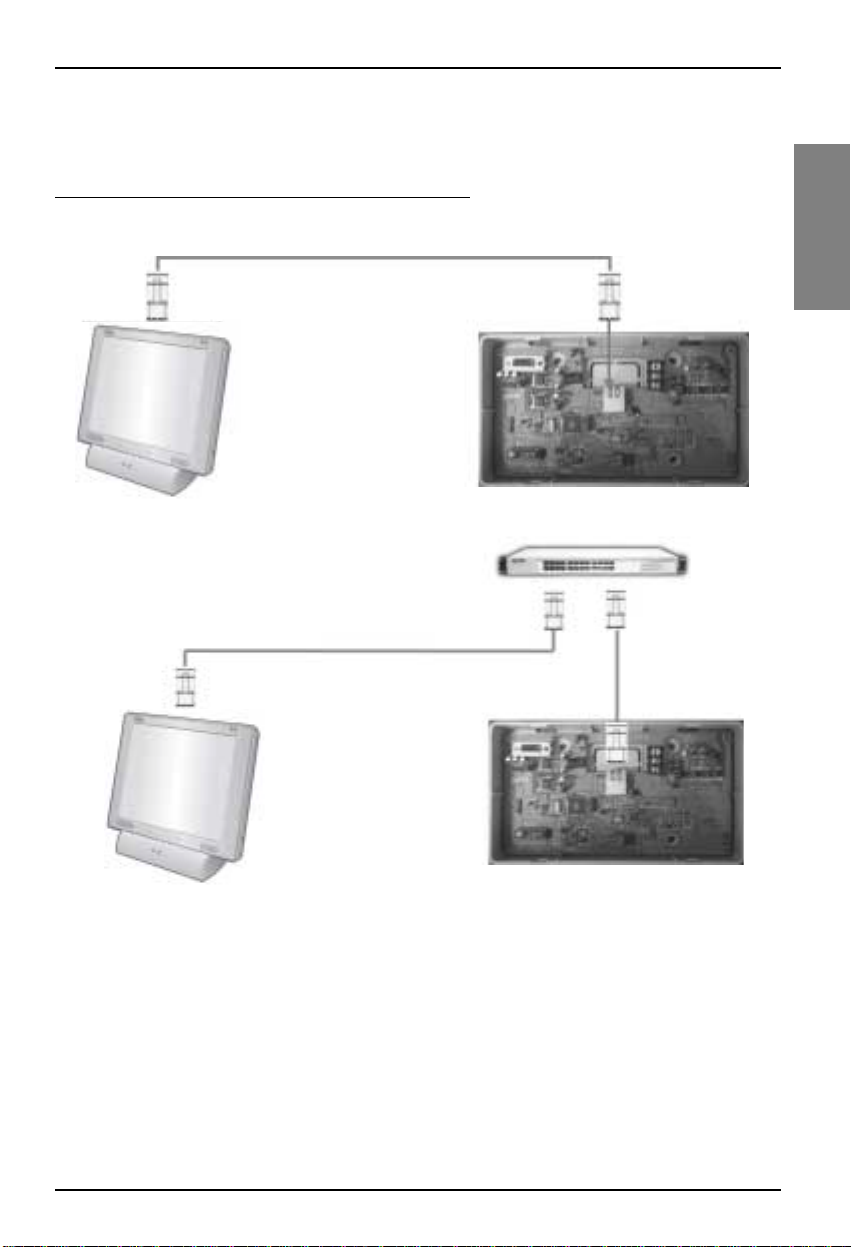
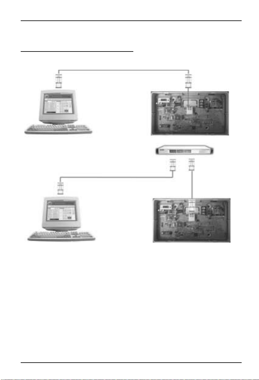
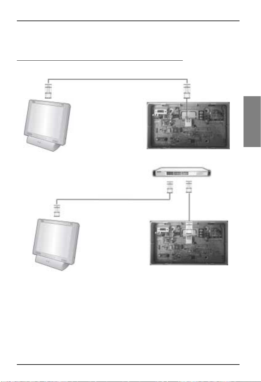
■ Connection
Delux
e central contr
oller connection
Cross Cable
Direct Cable
Direct Cable
Page 10
Wiring Diagram
10 CNU
PC central controller connection
Cross Cable
Direct Cable
Direct Cable
Use the cross cable if not using the hub.
If willing to use the hub, use the direct
cable to connect with the hub
Page 11
Network Interface Connection
Installation Manual 11
ENGLISH
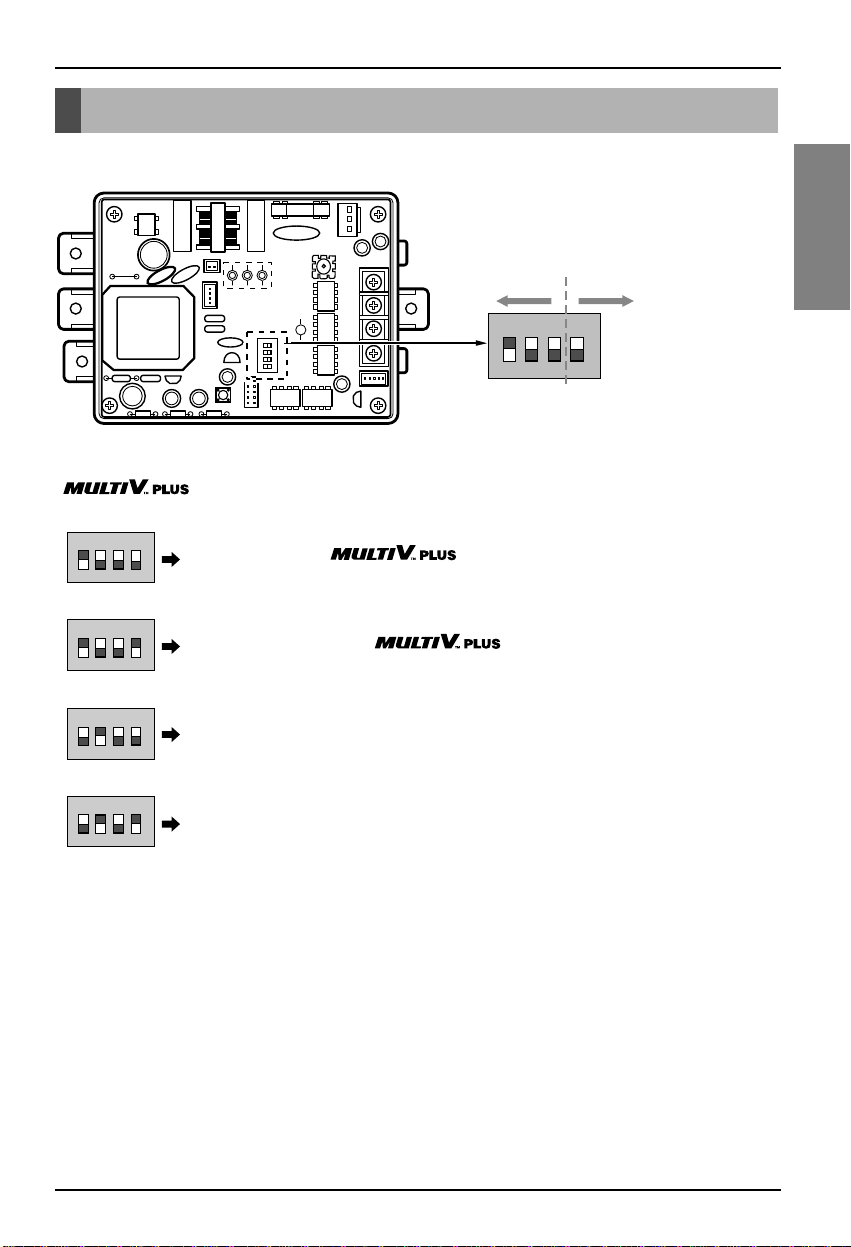
■ Dip Switch Configuration
Network Interface Connection
ON
L1 2 3 4
KSDO4H
ON KSDO 4H
ON KSDO4H
ON KSDO4H
ON KSDO4H
ON KSDO4H
Selection air-
conditioner type
Selection
network type
* LGAP : LG Air conditioner Protocol
& MPS MULTI Products Configuration Methods
& MPS
Inverter Product + Without LGAP central controller
Ex) DCC(PQCSW series) or PCC(PQCSS501A0/PQCSS502A0)
1 ON, Al others OFF:
MPS Multi Standard Product + Without LGAP central controller
Ex) DCC(PQCSW series) or PCC(PQCSS501A0/PQCSS502A0)
2 ON, All others OFF:
Multi Standard Product + With LGAP central controller
Ex) PCC(PQCSS513A0)
2 and 4 ON, All others OFF:
Inverter Product + With LGAP central controller
Ex) PCC(PQCSS513A0)
1 and 4 ON, Al others OFF :
& MPS
* Please refer the corresponding Central Controller installation manual if you want to know whether your Central
Controller is compatible with LGAP or not.
Page 12
12 CNU
CNU setup method
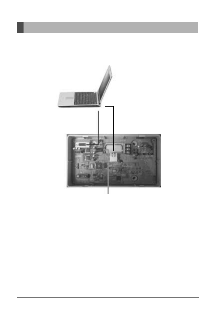
■ Connect with the PC
CNU setup method
❈ NOTICE : The CNU IP is automatically set-up 192.168.1.101 following factory shipment.
Do not set-up the CNU IP if wanting to use the PC Central Control without changing the CNU IP or
Deluxe central controller connection
RS22 connection
LAN connection
Connect Power
DC 9V Adaptor(supplied)
Page 13
CNU setup method
Installation Manual 13
ENGLISH
■ Set the PC environment for CNU IP setting
1) Check CNU , and connect between PC and CNU by 232 cable.
If your computer doesn't have 232port, Use USB to 232 Port cable.
2) Start up the RS232 Monitoring Program on the PC.
(You can download the RS232 Monitoring Program from LG air conditioner global website.)
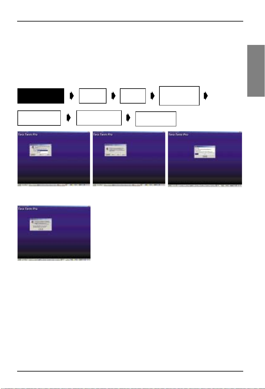
3) Follow below procedure.
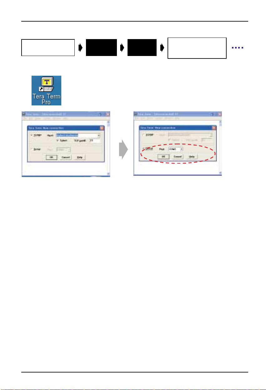
Install Teraterm
program
Click the
PCB’
s Reset button
1.Select language
2.Click Continue
5.Finishing step of the installation
Select
Change IP address
And Gateway
serial
3.Click Continue 4.Installing step of program
Change
port
Recheck the
Changed DATA
Serial port
Setup to change
baud rate
Page 14
CNU setup method
14 CNU
Install Teraterm
program
1. Click the starting icon
1. Select Serial
2. Reset the Port which is used by 232 cable.
Select
serial
Change
port
Serial port
Setup to change
boud rate
Page 15
CNU setup method
Installation Manual 15
ENGLISH
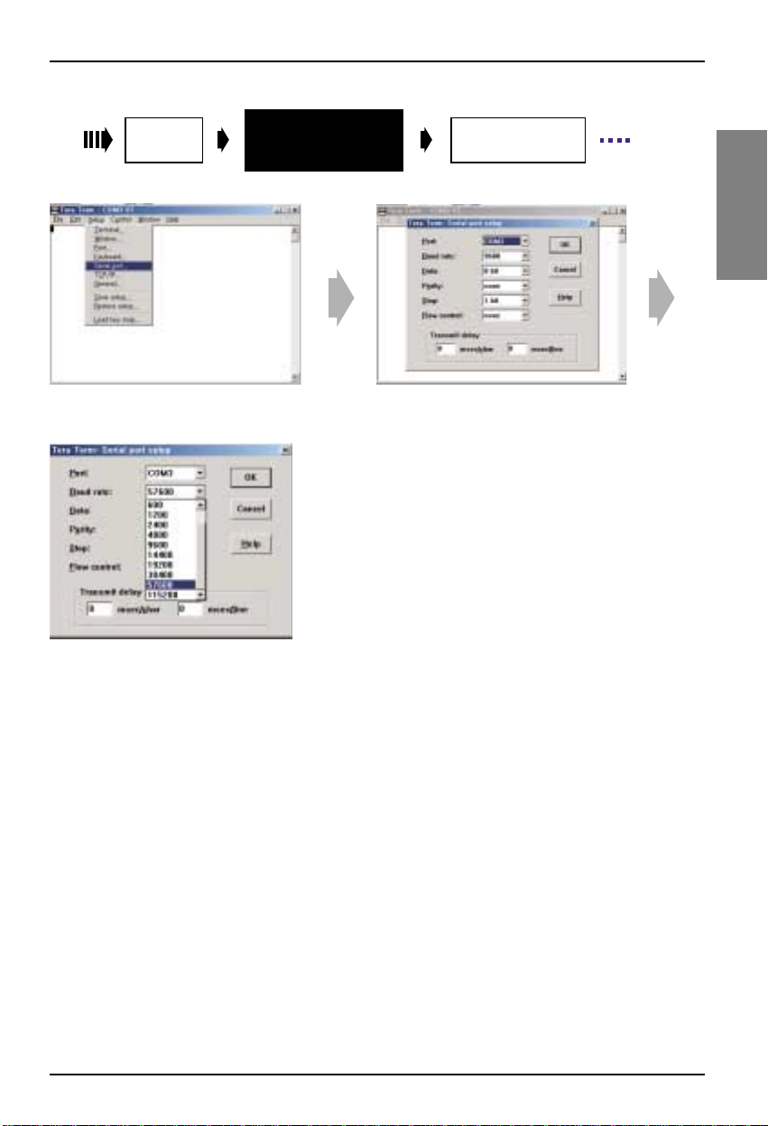
Change
port
1. Click the Setup button
2. choosing serial port
Serial port
Setup to change
boud rate
Click the
PCB’s Reset button
3. Change boud rate
4. Set 57600
Page 16
CNU setup method
16 CNU
Serial port
Setup to change
boud rate
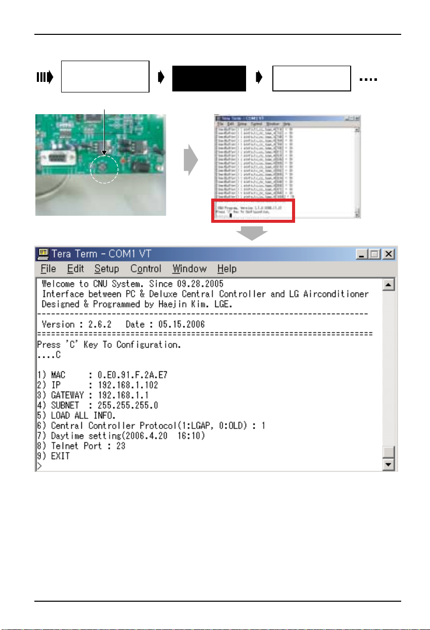
1. Click the PCB's reset button
Click the
PCB’s Reset button
1. type the character “C”
Change IP address
And Gateway
Page 17
CNU setup method
Installation Manual 17
ENGLISH
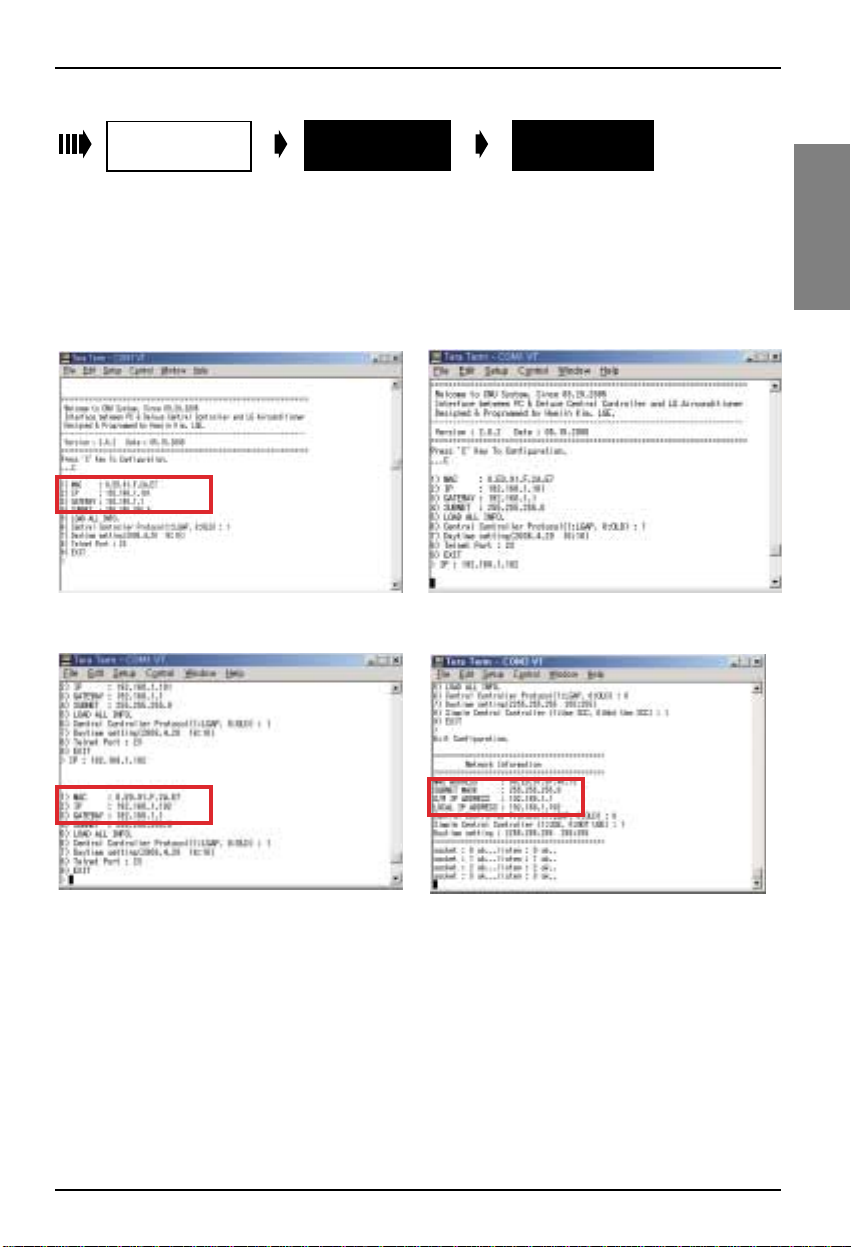
■ Check CNU Setting data
1) MAC : Device Address (Don't change)
2) IP : CNU internet address
3) Gateway : internet Gateway
4) Subnet : Subnet mask (Don't change)
5) Load all info : total information
6) Central Controller Protocol : Select protocol '0' or
'1', refer next page.
7) Daytime Setting
8) Telnet Port : 23 (Don't change)
9) EXIT
Click the
PCB’
s Reset button
Change IP address
And Gateway
Recheck the
Changed DATA
1. type character “2” 2. type IP address 192.168.1.102 , and
Click ENTER key
3. Check the changed IP address
4. If you finish setting, Type “9”
* Follow upper procedure and Change other
setting items properly
Page 18

CNU setup method
18 CNU
■ CNU Setup Configuration
Press the number which it wants changing
1. MAC address (Don't change)
00.E0.91.0F.XX.XX is an item which is specific value
2. IP : IP set up menu
- Use CNU IP set or change
- Default value in factory is 192.168.1.101
❈ Notice : Incase using private IP, Consult with network manager
3. GATEWAY : network gateway IP set up menu
- Use CNU network gateway IP set or change
- Default value in factory is 192.168.1.1
❈ Notice : Incase using private IP, Consult with network manager
6. Central controller Protocol(1:LGAP,0:OLD) : LGAP selection menu
• select '0' : in using Deluxe central controller or PC central controller without
LGAP(PQCSS501A0/PQCSS502A0)
• select '1' : in using PC central controller with LGAP(PQCSS513A0)
example)
- Central Controller Protocol(LGPA:1, OLD:0) ➔ After input 0, press ENTER
- Central Controller Protocol(LGAP:1, OLD:0) ➔ After input 1, press ENTER
❈ Notice : When the network set goes wrong and does not become the communication
7. Number 1,4,5,7,8 items are not setup Menu.
So, Don't change default value
❈ Notice : After all of settings are finished
You should escape set up mode by typing '9' otherwise, The CNU will not operate normally
Page 19
CNU Normal operation condition confirmation
Installation Manual 19
ENGLISH
■ Hardware operation condition confirmation
CNU Normal operation condition confirmation
1) Check CNU LED1 is continuously blinking : 485 communication LED
2) Check L06D, L07D LEDs are Lighting : LAN CABLE connection confirmation LED
3) Check L09D,L08D blinking : LAN communication condition confirmation LED
L08D blinking : connected Deluxe central controller(10M BPS)
L09D blinking : connected PC(100M BPS)
❈ Notice : If the LAN cable is are not connected between PC(or DCC) and CNU then the LED6D,7D are not light
■ LAN communication condition confirmation
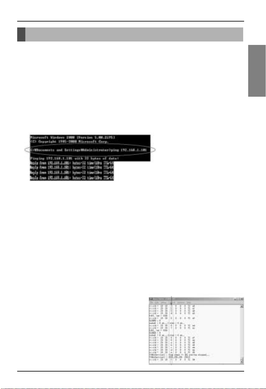
1) After connecting the LAN CABLE, executing, DOS Command of the PC which is connected
2) PING test : type 'ping' and 'CNU IP' then Enter key
ex) PING 192.168.1.101 (The CNU IP will be different which is real set ,so type real CNU IP)
❈ Notice : The response time will be different to system condition
If ping test is fail(request tine out) then check below condition
- CNU IP is correct?
- PC Network information has same with the CNU IP information
ex) If CNU IP is 192.168.1.101 then the PC network information does to have a same network
information 192.168.1.XXX(except same CNU IP number or 1 )
3) When PING test executes well, LAN communication operates in the normality.
■ 485 Communication condition confirmation
1) Before confirm 485 communication condition, check indoor address setting and 485 G/W operation LED's condition
and power resource condition.
2) Connecting RS232 cable and running RS232 monitoring program
3) In order to appear information in monitoring program window, Setup Com port and Baud rate to 57600.
4) The data will come up and it will be able to confirm a number of indoor
Setup address of indoor appears, 485 communication
operational condition of CNU is normality
ex) number monitoring of connected indoor
❈ Notice : The indoor number searching time could be delayed in in
the condition which searches
When neither information of the indoor information is searched
Check below check points
1) Check Indoor unit address are set correct or not
2) Check the 485 gateway setting (s/w setting, connect
connection..etc.)
3) Check 485 communication line is correct or not BUS_A, BUS_B
Indoor number
Page 20

Memo
20 CNU
Page 21

LG
CNU
IMPORTANTE
• Leggere per intero questo manuale
d’installazione prima di installare il prodotto.
• Il servizio di installazione deve essere eseguita
solo da personale autorizzato e in conformità
con gli standard di cablaggio nazionali.
• Dopo aver letto interamente il manuale
d’installazione, conservarlo per riferimento
futuro.
Modello: PQNFG14B0
MANUALE D’INSTALLAZIONE
ITALIANO
Page 22

2 CNU
CNU
SOMMARIO
■ Istruzioni di sicurezza.............................................................................................3
■ Descrizione dei componenti ..................................................................................6
Componenti di un CNU.............................................................................................6
Connessione CNU....................................................................................................7
■ Schema di cablaggio ..............................................................................................8
Multi-V Super (Plus) e Prodotto MPS .......................................................................8
Collegamenti.............................................................................................................9
■ Collegamento interfaccia di rete .........................................................................11
Configurazione del commutatore............................................................................11
■ Metodo di configurazione del CNU .....................................................................12
Collegamento al PC................................................................................................12
Configurare l’ambiente PC per l’impostazione dell’IP del CPU...............................13
Configurazione dell’impostazione del CNU.............................................................18
■ Conferma delle condizioni operative normali del CNU .....................................19
Conferma delle condizioni operative dell’hardware ................................................19
Conferma delle condizioni di comunicazione LAN .................................................19
Conferma delle condizioni di comunicazione 485...................................................19
Page 23
Istruzioni di sicurezza
Manuale di installazione 3
ITALIANO
L’installazione del prodotto
deve essere sempre eseguita
dal centro di assistenza o da
altra società di installazioni.
Utilizzare solo i componenti
specificati.
Per reinstallare un prodotto
precedentemente installato,
rivolgersi al centro di assistenza
o ad altra società di installazioni.
• In caso contrario, si
potrebbero verificare
incendi, scosse elettriche,
esplosioni, lesioni o danni.
•
In caso contrario, si potrebbero
verificare incendi, scosse
elettriche, esplosioni, lesioni, danni
o problemi di funzionamento.
• In caso contrario, si
potrebbero verificare incendi,
scosse elettriche, esplosioni,
lesioni o danni.
Non utilizzare gas o altro materiale
infiammabile nelle vicinanze del prodotto.
Non smontare, riparare o modificare il
prodotto a proprio piacimento.
• In caso contrario, si potrebbero verificare
incendi e problemi di funzionamento del
prodotto.
• In caso contrario, si potrebbero verificare
incendi e scosse elettriche.
Istruzioni di sicurezza
Per evitare infortuni all'utente o a terzi e danni alla proprietà, attenersi alle seguenti istruzioni.
■ L’uso errato causato dalla mancata osservanza delle istruzioni può causare danni o lesioni.
L’importanza è classificata dalle seguenti indicazioni.
Questo simbolo indica la possibilità di decesso o di grave infortunio.
Questo simbolo indica la possibilità di infortunio o danni alle cose.
■ Il significato dei simboli utilizzati in questo manuale è spiegato di seguito.
Azione/operazione da non fare.
Attenersi alle istruzioni.
AVVERTENZA
■
FASE DI INSTALLAZIONE
SPECIFIED
PARTS
Benzene
Ether
Thinner
AVVERTENZA
ATTENZIONE
Page 24
Istruzioni di sicurezza
4 CNU
Non installare in luoghi esposti alla pioggia. Non installare in luoghi umidi.
• In caso contrario si potrebbero verificare dei
guasti.
• In caso contrario si potrebbero verificare dei
guasti.
Non sostituire né allungare il
cavo dell’alimentazione
elettrica a proprio piacimento.
Non esporre l’unità a fonti di
calore.
Non utilizzare fonti di calore
in vicinanza della linea di
alimentazione elettrica.
•
In caso contrario, si potrebbero
verificare incendi e scosse elettriche.
• Ciò potrebbe causare incendi. •
In caso contrario, si potrebbero
verificare incendi e scosse elettriche.
Non versare acqua
all’interno del prodotto.
Non posizionare oggetti
pesanti sul cavo
dell’alimentazione elettrica.
Non posizionare oggetti
pesanti sull’unità.
• In caso contrario, si
potrebbero verificare
scosse elettriche o guasti.
• In caso contrario, si
potrebbero verificare incendi e
scosse elettriche.
•
In caso contrario si potrebbero
verificare problemi di
funzionamento del prodotto.
Rivolgersi sempre al centro di
assistenza o alla società di
installazioni nei casi in cui il prodotto
venga a contatto con l’acqua.
Bambini, anziani e persone
con problematiche fisiche
possono utilizzarlo sotto
l’altrui supervisione.
Non urtare il prodotto.
•
In caso contrario, si potrebbero
verificare incendi e scosse
elettriche.
•
In caso contrario, si
potrebbero verificare
incidenti o guasti al prodotto.
•
Se il prodotto viene urtato,
si potrebbero verificare
problemi di funzionamento.
■ USO
Page 25
Istruzioni di sicurezza
Manuale di installazione 5
ITALIANO
Non pulire il prodotto con
detergenti o solventi aggressivi
ma utilizzare esclusivamente
un panno morbido.
In caso di versamento di acqua
sui componenti elettrici,
utilizzare l’unità solo dopo aver
eliminato ogni traccia d’acqua.
Evitare che oggetti metallici
come collane, monete, chiavi,
orologi, ecc. entrino in contatto
con i terminali della batteria.
•
In caso contrario, si potrebbero
verificare incendi ed eventualmente
la deformazione del prodotto.
•
In caso contrario si potrebbero
verificare problemi di
funzionamento del prodotto.
•
In caso contrario si potrebbero
verificare problemi di funzionamento
del prodotto e lesioni.
ATTENZIONE
■ USO
W
a
x
Thinner
Page 26

Descrizione dei componenti
Descrizione dei componenti
6 CNU
■ Componenti di un CNU
LGAP
SCATOLA CNU
Tensione di ingresso: DC9V 2.0A
Porta ingresso/uscita: RS232 1ea
RS485 1ea
LAN 1ea
Dimensione
200.0
120.0
7.5
20.0
55.0
35.0
Alimentazione
DC 9V , 2.0A
Standard internazionale
Tipo IEC320 C8
Cavo di alimentazione
NOTA: Spec. ingresso CA
- Ingresso universale -100~250 VAC
- Da tavolo o con presa a muro
Page 27
Descrizione dei componenti
Manuale di installazione 7
ITALIANO
■ Connessione CNU
Collegamento del terminale di comunicazione
RS-485 con PMNFP14A0 (PMNFP14A1):
BUS_A, B
• Istruzioni per il collegamento della linea di
comunicazione RS-485: Collegare la linea di
comunicazione 485 come mostrato
nell’immagine in basso mediante il conduttore
interno e il giunto.
Adattatore connettore
di alimentazione CC 9
V (in dotazione)
PQNFG14B0 ---PMNFP14A0
(PMNFP14A1)
Tasto reset
• NOTA
questo terminale serve a garantire la stabilità
delle comunicazioni, evitare quindi di rimuoverlo
e collegarlo all’altra linea
Connettore RJ45:
Collegamento con HUB
o unità di controllo
centrale deluxe/PC
L06D: Collegamento di LAN H/W (LINK LED)
L07D: Collegamento di LAN H/W LED(DUPLEX)
L08D: LED di comunicazione 10MEGA BASE
(quando CNU II è collegato con l’unità di controllo centrale deluxe)
L09D: LED di comunicazione 100MEGA BASE
(quando CNU II è collegato con l’unità di controllo centrale PC)
L10D: LED RILEVATORE DI COLLISIONI
BUS_A ---- BUS_A
BUS_B ---- BUS_B
Page 28
Schema di cablaggio
8 CNU
ON
L1 2 3 4
KSDO4H
CNU PCB
BUS_A
BUS_A
BUS_B
BUS_B
Connessione
CNU
DC 9V collegamento adattatore
Unità di controllo centrale PC
Morsettiera unità esterna multiv
DC 9V
ABEFCD
VCC GND
CN_CENTRAL
Multi-V Super (Plus) o
Prodotto MPS PCB
principale esterno
Consultare il metodo di impostazione dell’interfaccia di
rete a pagina 11.
Viene illustrato come configurare il commutatore PI
485(M).
■ SUPER(PLUS) e Prodotto MPS
Schema di cablaggio
❈ NOTA : Utilizzare la morsettiera qualora Multi V e altri modelli non fossero necessari. Se questa non è
presente, effettuare collegamenti diretti.
Page 29
Schema di cablaggio
Manuale di installazione 9
ITALIANO
■ Collegamenti
Collegamento unità di contr
ollo centrale delux
e
Cavo trasversale
Cavo diretto
Cavo diretto
Page 30

Schema di cablaggio
10 CNU
Collegamento unità di controllo centrale PC
Cavo trasversale
Cavo diretto
Cavo diretto
Utilizzare il cavo trasversale se non si
sta utilizzando l’hub. Se si intende
utilizzare l’hub, collegarlo con il cavo
diretto
Page 31

Network Interface Connection
Manuale di installazione 11
ITALIANO
■ Configurazione del commutatore
Collegamento interfaccia di rete
ON
L1 2 3 4
KSDO4H
ON KSDO 4H
ON KSDO4H
ON KSDO4H
ON KSDO4H
ON KSDO4H
Selezionare aria-
tipo di
condizionatore
Selezionare
tipo di rete
* LGAP : Protocollo condizionatore d’aria LG
e MPS MULTIMetodi di configurazione dei prodotti
& MPS
Invertitore prodotto + unità di controllo centrale senza LGAP
Ex) DCC(PQCSW series) or PCC(PQCSS501A0/PQCSS502A0)
1 ON, Tutti gli altri OFF:
Prodotto standard multi MPS + unità di controllo centrale senza LGAP
Ex) DCC(PQCSW series) or PCC(PQCSS501A0/PQCSS502A0)
2 ON, Tutti gli altri OFF:
Prodotto standard multi MPS + unità di controllo centrale
senza LGAP. Ex) PCC(PQCSS513A0)
2 and 4 ON, Tutti gli altri OFF:
Invertitore prodotto + unità di controllo centrale senza
LGAP. Ex) PCC(PQCSS513A0)
1 and 4 ON, Tutti gli altri OFF :
& MPS
* Consultare il manuale di installazione corrispondente dell’unità di controllo centrale per conoscere le
caratteristiche di compatibilità dell'unità di controllo centrale con LGAP.
Page 32

12 CNU
Metodo di configurazione del CNU
■ Collegare al PC
Metodo di configurazione del CNU
❈ NOTA : L’IP di CNU viene automaticamente impostato a 192.168.1.101 in fabbrica.
Non impostare l’IP di CNU se si intende utilizzare l’unità di controllo centrale PC senza modificare l’IP
di CNU o il collegamento dell’unità di controllo centrale deluxe.
Collegamento RS22
Collegamento LAN
Collegamento alimentazione
Adattatore CC 9 V (in dotazione)
Page 33

Metodo di configurazione del CNU
Manuale di installazione 13
ITALIANO
■ Impostare l’ambiente PC per l’impostazione dell’IP del CPU
1) Controllare il CNU e collegarlo al PC mediante il cavo 232.
Se il computer non dispone di una porta 232, utilizzare la porta USB per il cavo 232.
2) Avviare il programma di monitoraggio RS232 sul PC.
(È possibile scaricare il programma di monitoraggio RS232 dal sito globale dei condizionatori d’aria LG).
3) Adottare la seguente procedura.
Installare il programma
Teraterm
Fare clic sul pulsante
Reset PCB
1. Selezionare la lingua
2. Fare clic su Continua
5. Fase di completamento dell’installazione
Selezionare
Seriale
Cambiare indirizzo
IP e gateway
3. Fare clic su Continua 4. Fase di installazione del
Cambiare
porta
Impostare per
cambiare baud rate
Ricontrollare i
dati modificati
Porta seriale
programma
Page 34

Metodo di configurazione del CNU
14 CNU
Installare il programma
Teraterm
1. Fare clic sull’icona di avvio
1. Selezionare Seriale
2. Ripristinare la porta utilizzata dal cavo 232.
Selezionare
seriale
Cambiare
porta
Porta seriale
Impostare per cambiare
baud rate
Page 35

Metodo di configurazione del CNU
Manuale di installazione 15
ITALIANO
Cambiare
porta
1. Fare clic sul pulsante Setup
2. Scelta della porta seriale
Porta seriale
Impostare per cambiare
baud rate
3. Modificare la velocità di trasmissione in Baud
Fare clic sul pulsante
di reset di PCB
4. Impostare 57600
Page 36

Metodo di configurazione del CNU
16 CNU
Porta seriale
Impostare per cambiare
baud rate
1. Fare clic sul pulsante di reset di PCB
Fare clic sul pulsante
di reset di PCB
1. digitare il carattere "C"
Modificare l’indirizzo
IP e il gateway
Page 37

Metodo di configurazione del CNU
Manuale di installazione 17
ITALIANO
■ Controllo dati impostazione CNU
1) MAC: Indirizzo dispositivo (Non modificarlo)
2) IP: Indirizzo internet CNU
3) Gateway: Gateway internet
4) Subnet: Subnet mask (Non modificarlo)
5) Caricare tutte le informazioni: informazioni totali
6)
Protocollo unità di controllo centrale: Selezionare
protocollo ‘0’ o ‘1’, fare riferimento alla pagina successiva.
7) Impostazioni diurne
8) Porta Telnet: 23 (Non modificarla)
9) USCITA
Fare clic sul pulsante
di reset di PCB
Modificare l’indirizzo
IP e il gateway
Ricontrollare i
dati modificati
1. Digitare il carattere "2" 2. Digitare l’indirizzo IP 192.168.1.102 e fare clic
sul tasto ENTER
3. Controllare l’indirizzo IP modificato
4. Se l’impostazione è completata, digitare “9”
* Seguire la procedura descritta sopra e
modificare come necessario altri parametri
di impostazione
Page 38

Metodo di configurazione del CNU
18 CNU
■ Configurazione dell’impostazione del CNU
Premere il numero che si desidera modificare
1. Indirizzo MAC (Non modificarlo)
00.E0.91 .0F.XX.XX è un valore specifico
2. IP: menu di configurazione dell’IP
- Utilizzare l’IP CNU impostato o modificarlo
- Il valore predefinito in fabbrica è 192.168.1.101
❈ Avviso : Se si utilizza un IP privato, contattare il gestore della rete
3. GATEWAY: menu di configurazione dell’IP del gateway di rete
- Utilizzare l’IP del gateway di rete di CNU impostato o modificarlo
- Il valore predefinito in fabbrica è 192.168.1.1
❈ Avviso : Se si utilizza un IP privato, contattare il gestore della rete
6. Protocollo unità di controllo centrale (1:LGAP,0:PRECEDENTE): Menu di selezione LGAP
* selezionare '0': se si utilizza l’unità di controllo centrale deluxe o l’unità di controllo centrale PC senza
LGAP(PQCSS501 A0/PQCSS502A0)
* selezionare '1': se si utilizza l’unità di controllo centrale PC con LGAP (PQCSS513A0)
esempio)
- Protocollo unità di controllo centrale (LGPA:1, PRECEDENTE:0) -» Dopo aver digitato 0, premere ENTER
- Protocollo unità di controllo centrale (LGAP:1, PRECEDENTE:0) -» Dopo aver digitato 1, premere ENTER
❈ Avviso : Se le impostazioni di rete sono errate e non consentono la comunicazione
7. Le voci 1, 4, 5, 7, 8 non fanno parte del menu di impostazione. Pertanto, non modificare il valore predefinito
❈ Avviso : Al termine di tutte le impostazioni
Uscire dalla modalità di impostazione digitando '9', in caso contrario il CNU non è in grado di
funzionare normalmente.
Page 39

1) Prima di confermare le condizioni di comunicazione 485, controllare le impostazioni dell’indirizzo interno e le
condizioni operative del LED 485 G/W e dell'alimentazione.
2) Collegamento del cavo RS232 ed esecuzione del programma di monitoraggio RS232
3) Per visualizzare le informazioni nella finestra del programma di monitoraggio, impostare la porta Com e la velocità
di trasmissione in Baud a 57600.
4)
I dati verranno visualizzati e sarà possibile confermare un numero interno
Appare l’indirizzo di impostazione interno, comunicazione 485 la
condizione operativa di CNU è normale
es) monitoraggio numero dell’interno collegato
❈ Avviso :
Il tempo di ricerca del numero interno può essere maggiore
in funzione delle condizioni in cui è effettuata la ricerca
Durante la ricerca di informazioni dell’interno, controllare i punti seguenti
1) Verificare se l’indirizzo dell’unità interna è corretto
2) Controllare le impostazioni di gateway 485 (impostazioni
interruttore, collegamenti, ecc.)
3) Controllare che la linea di comunicazione 485 sia corretta e non
BUS_A, BUS_B
Conferma delle condizioni operative normali del CNU
Manuale di installazione 19
ITALIANO
■ Conferma delle condizioni operative dell’hardware
Conferma delle condizioni operative normali del CNU
1) Controllare che il LED1 del CNU lampeggi in modo continuo: LED di comunicazione 485
2) Controllare che i LED L06D, L07D siano illuminati: LED di conferma del collegamento del cavo LAN
3) Controllare che L09D,L08D lampeggino: LED di conferma delle condizioni di comunicazione LAN
L08D lampeggiante: L09D unità di controllo centrale deluxe collegata
(10M BPS) lampeggiante: collegata al PC (100M BPS)
❈ Avviso : Se il cavo LAN non è collegato tra PC (o DCC) e CNU, i LED LED6D,7D non si illuminano
■ Conferma delle condizioni di comunicazione LAN
1) Dopo aver collegato il cavo LAN, eseguire il comando DOS del PC collegato
2) Test PING: digitare ‘ping’ e ‘CNU IP’ e fare clic sul tasto Enter
es) PING 192.168.1.101 (L’IP di CNU sarà diverso, digitare l’IP effettivo) Conferma delle condizioni operative
normali del CNU
❈ Avviso : Il tempo necessario per la risposta varia in base alle condizioni di sistema
Se il test ping fallisce (richiesta terminata) controllare le condizioni seguenti
- L’IP di CNU è corretto?
- Le informazioni di rete del PC sono le stesse dell’IP di CNU
es) Se l’IP di CNU è 192.168.1.101 anche le informazioni di rete di PC sono 192.168.1.XXX(ad
eccezione dello stesso numero di IP di CNU o 1 )
3) Se il test PING ha esito positivo, la comunicazione LAN funziona normalmente.
■ Conferma delle condizioni di comunicazione 485
Numero interno
Page 40

Note
20 CNU
Page 41

ESPAÑOL
LG
CNU
IMPORTANTE
• Lea completamente este Manual de instalación
antes de instalar el producto.
• Las tareas de instalación deben realizarse de
acuerdo con la normativa eléctrica nacional y
sólo puede llevarlas a cabo personal autorizado.
• Conserve este Manual de instalación para
futuras consultas después de haberlo leído
completamente.
Modelo: PQNFG14B0
MANUAL DE INSTALACIÓN
Page 42

2 CNU
CNU
ÍNDICE
■ Precauciones de seguridad ...................................................................................3
■ Descripción de las piezas ......................................................................................6
Piezas de una CNU ..................................................................................................6
Conexiones de la CNU .............................................................................................7
■ Diagrama de cableado............................................................................................8
Multi V SUPER(PLUS) Y PRODUCTOS MPS
...........................................................8
Conexión
...................................................................................................................9
■ Conexión del interfaz de red................................................................................11
Configuración del interruptor selector .....................................................................11
■ Método de configuración de la CNU ...................................................................12
Conexión a un PC...................................................................................................12
Configuración del PC con la IP de la CNU .............................................................13
Configuración y ajuste de la CNU...........................................................................18
■ Confirmación del estado de correcto funcionamiento de la CNU....................19
Confirmación del estado de funcionamiento del equipo .........................................19
Confirmación del estado de la comunicación LAN .................................................19
Confirmación del estado de la comunicación 485 ..................................................19
Page 43

Precauciones de seguridad
Manual de Instalación 3
ESPAÑOL
Debe solicitar siempre la
instalación del producto a nuestro
Centro de servicio o a una empresa
de instalación profesional.
Utilice las piezas
especificadas.
Para reinstalar un producto ya ha
sido instalado, acuda a nuestro
Centro de servicio o a una empresa
de instalación profesional.
•
De lo contrario, pueden
producirse incendios,
descargas eléctricas,
explosiones, daños o lesiones.
•
De lo contrario, pueden
producirse incendios, descargas
eléctricas, explosiones, lesiones,
daños o averías.
• De lo contrario, pueden
producirse incendios,
descargas eléctricas,
explosiones, daños o lesiones.
No mantenga o utilice gas inflamable o cualquier otro
material inflamable en las inmediaciones del producto.
No desmonte, repare ni modifique usted
mismo el producto.
• De lo contrario, podría producirse un
incendio y una avería en el producto.
• De lo contrario, puede haber riesgo de
incendios y descargas eléctricas.
Precauciones de seguridad
Para evitar lesiones al usuario o a otras personas y daños materiales, deben seguirse estas
instrucciones.
■ Una utilización incorrecta por ignorar las instrucciones provocará lesiones o daños. La gravedad se
clasifica mediante las siguientes indicaciones.
Este símbolo indica la posibilidad de muerte o lesión grave.
Este símbolo indica la posibilidad de lesiones o daños materiales.
■ Los significados de los símbolos utilizados en este manual se muestran abajo.
No lo haga.
Asegúrese de seguir las instrucciones.
ADVERTENCIA
■ AL REALIZAR LA INSTALACIÓN
SPECIFIED
PAR T S
Benzene
Ether
Thinner
ADVERTENCIA
PRECAUCIÓN
Page 44

Precauciones de seguridad
4 CNU
No lo instale en un lugar expuesto a la lluvia.
No lo instale en lugares húmedos.
• De lo contrario, podría averiarse. • De lo contrario, podría averiarse.
No cambie o prolongue el
cable del suministro eléctrico
usted mismo.
Asegúrese de no colocar el
producto cerca del fuego.
No utilice equipos que
desprendan calor cerca de
la línea de suministro
eléctrico.
•
De lo contrario, pueden producirse
incendios y descargas eléctricas.
• De lo contrario, podría
producirse un incendio.
•
De lo contrario, pueden producirse
incendios y descargas eléctricas.
No derrame agua en el
interior del producto.
No coloque materiales
pesados sobre el cable del
suministro eléctrico.
No coloque materiales
pesados sobre el producto.
• De lo contrario, pueden
producirse descargas
eléctricas o averías.
• De lo contrario, pueden
producirse incendios y
descargas eléctricas.
• De lo contrario, podría
averiarse.
En caso de que el producto haya sido
sumergido en agua, contacte siempre
con nuestro Centro de servicio o con
una empresa de instalación profesional.
Tanto niños como ancianos y
personas discapacitadas
deben utilizarlo bajo
supervisión.
No golpee el producto.
•
De lo contrario, pueden
producirse incendios y descargas
eléctricas.
• De lo contrario, podrían
producirse accidentes o
averías en el producto.
• Si se golpea el producto,
podrían producirse
averías en el producto.
■ AL UTILIZARLO
Page 45

Precauciones de seguridad
Manual de Instalación 5
ESPAÑOL
No limpie el producto con
detergentes fuertes o
disolventes. Utilice sólo un
trapo suave.
Si se ha derramado agua
sobre una parte con carga
eléctrica, utilice el producto
después de quitar el agua.
No permita que objetos metálicos
como collares, monedas, llaves,
relojes, etc. entren en contacto
con el terminal de batería.
• De lo contrario, pueden
producirse incendios y
deformaciones en el producto.
• De lo contrario, podría
averiarse.
• De lo contrario, podría
averiarse y causar lesiones.
PRECAUCIÓN
■ AL UTILIZARLO
Wax
Thinner
Page 46

Descripción de las piezas
Descripción de las piezas
6 CNU
■ Piezas de una CNU
LGAP
CAJA DE LA CNU
Dimensiones
120.0
200.0
20.0
7.5
55.0
35.0
Voltaje de entrada: CC 9V 2.0A
Puerto de entrada/salida: RS232 1ea
RS485 1ea
LAN 1ea
Fuente de alimentación
CC 9V, 2.0 A
Estándar internacional
Tipo IEC320 C8
Cable de alimentación
NOTA: CA de entrada especificada
- 100~250 V CA entrada universal
- Modelo de sobremesa o de toma de pared
Page 47

Descripción de las piezas
Manual de Instalación 7
ESPAÑOL
■ Conexiones de la CNU
Botón Reset
Conector RJ45:
Conectar al HUB OR
Adaptador CC 9V de
conector de
alimentación
(suministrado)
deluxe/controlador
central del PC
Terminal de comunicaciones RS-485
Conectar al PMNFP14A0 (PMNFP14A1):
BUS_A, B
• Precauciones al conectar la línea de
comunicaciones RS-485: Cuando conecte la
línea de comunicaciones 485, hágalo como se
indica en la imagen de abajo. Utilice el conector
de cables y el amarre suministrados.
PQNFG14B0 ---PMNFP14A0
(PMNFP14A1)
BUS_A ---- BUS_A
BUS_B ---- BUS_B
• AVISO
Este terminal sirve para dar la estabilidad de
las comunicaciones. No lo extraiga o lo
conecte a otra línea.
L06D: Conexión LAN H/W (LED de enlace)
L07D: Conexión del LED LAN H/w (DÚPLEX)
L08D: LED de comunicaciones de 10 MEGAS BASE.
(cuando la CNU II está conectada al controlador central Deluxe)
L09D: LED de comunicaciones de 100 MEGAS BASE (cuando la CNU II
está conectada al controlador central del PC)
L10D: LED DE DETECCIÓN DE COLISIONES
Page 48

Diagrama de cableado
8 CNU
ON
L1 2 3 4
KSDO4H
CNU PCB
BUS_A
BUS_A
BUS_B
BUS_B
Conexión de la CNU
Conexión del adaptador CC 9V
BLOQUE TERMINAL PARA EXTERIORES MULTI V
CC 9V
ABEFCD
VCC GND
CN_CENTRAL
Multi-V SUPER (PLUS) o
PCB principal para
exteriores de producto
MPS
Consulte el método de configuración de la interfaz de
red de la página 11. Explica cómo configurar el
interruptor selector PI 485(M).
■ SUPER(PLUS) Y PRODUCTOS MPS
Diagrama de cableado
❈ AVISO : El uso del bloque terminal en el caso de Multi V y otros modelos no siempre puede ser necesario. Si
no está presente, haga conexiones directas.
Page 49

Diagrama de cableado
Manual de Instalación 9
ESPAÑOL
■ Conexión
C
o
nexión del controlador central Deluxe
Cable cruzado
Cable directo
Cable directo
Page 50

Diagrama de cableado
10 CNU
C
onexión del controlador central Deluxe
Cable cruzado
Cable directo
Cable directo
Utilice un cable cruzado en caso de no
usar el concentrador. Si desea utilizar el
concentrador, utilice el cable directo
Page 51

Conexión del interfaz de red
Manual de Instalación 11
ESPAÑOL
■ Configuración del interruptor selector
Conexión del interfaz de red
ON
L1 2 3 4
KSDO4H
ON KSDO 4H
ON KSDO4H
ON KSDO4H
ON KSDO4H
ON KSDO4H
Selección del tipo
de aire
acondicionado
Selección del
tipo de red
* LGAP: Protocolo de aire acondicionado LG
y métodos de configuración de productos MPS MULTI
y MPS 1 ON (encendido), el resto OFF (apagado):
2 ON (encendido), el resto OFF (apagado): Producto MPS multiestándar +
Producto multiestándar +
2 y 4 ON (encendido), el resto OFF (apagado):
1 y 4 ON (encendido), el resto OFF (apagado):
y MPS
Producto inversor + Con controlador central LGAP
Ej.) DCC (serie PQCSW) o PCC (PQCSS501A0/PQCSS502A0)
Sin controlador central LGAP
Ej.) DCC (serie PQCSW) o PCC (PQCSS501A0/PQCSS502A0)
Con controlador central LGAP
Ej.) PCC (PQCSS513A0)
Producto inversor + Con controlador central LGAP
Ej.) PCC (PQCSS513A0)
* Solicite el manual de instalación del controlador central correspondiente si desea saber si su controlador central
es compatible con LGAP.
Page 52

12 CNU
Método de configuración de la CNU
■ ConexiónaunPC
Método de configuracióndelaCNU
❈ AVISO :LaIPdelaCNUquevieneconfiguradapordefectodefábrica es 192.168.1.101.
No configure la IP de la CNU si desea utilizar el control central del PC sin cambiar la IP de la CNU o la
conexión del controlador central Deluxe.
Conexión RS22
Conexión LAN
Alimentación
Adaptador CC 9V (suministrado)
Page 53

Método de configuración de la CNU
Manual de Instalación 13
ESPAÑOL
■ Configuración del PC con la IP de la CNU
1) Compruebe la CNU y conéctela al PC mediante el cable 232.
Si su ordenador no dispone de un puerto 232, utilice el USB con el cable del puerto 232.
2) En el PC, arrancar el programa de monitoreo RS232.
(Puede descargarse el programa de monitoreo RS232 del sitio web global de aire acondicionado LG.)
3) Siga el siguiente procedimiento.
Instale el programa
Teraterm
Pulsar el botón
Reset de la PCB
1. Seleccione el idioma
2. Pulse continuar
5. Fin de la instalación
Seleccione
serie
Cambiar la dirección
IP y la puerta de acceso
3. Pulse continuar 4. Inicio de la instalación del
Cambie el
puerto
Vuelva a comprobar
los cambios cambiados
Configure el puerto
de serie para cambiar
la velocidad de transmisión
programa
Page 54

Método de configuración de la CNU
14 CNU
Instale el programa
Teraterm
1. Pulse el icono del programa
1. Seleccione serie
2. Reinicie el puerto utilizado por el cable 232.
Seleccione
serie
Cambie
el puerto
Configure el puerto de
serie para cambiar la
velocidad de transmisión
Page 55

Método de configuración de la CNU
Manual de Instalación 15
ESPAÑOL
Cambie el
puerto
1. Pulse el botón Setup
2. Elija el puerto de serie
Configure el puerto de
serie para cambiar la
velocidad de transmisión
3. Cambie la velocidad de transmisión
Pulse el botón
Reset de la PCB
4. Fíjela en 57600
Page 56

Método de configuración de la CNU
16 CNU
Configurar el puerto de
serie para cambiar la
velocidad de transmisión
1. Pulsar el botón Reset de la PCB
Pulsar el botón
Reset de la PCB
1. Teclee “C”
Cambiar la dirección
IP y la puerta de acceso
Page 57

Método de configuración de la CNU
Manual de Instalación 17
ESPAÑOL
■
CompruebelosdatosdeconfiguracióndelaCNU
1) Dirección (no cambiar)
2) IP: DireccióndeInternetdelaCNU
3) Gateway (puerta de acceso): Puerta de acceso
de Internet
4)
Subset (subred): Máscara de subred (no cambiar)
5) Load all info (Cargar toda la información):
Información completa
6) Central Controller Protocol (Protocolo del
controlador central): Seleccionar protocolo '0' ó '1',
consultar la página siguiente.
7) Daytime Setting (Configuracióndiurna)
8) Telnet Port (Puerto Telnet): 23 (no cambiar)
9) EXIT (SALIR)
Pulsar el botón
Reset de la PCB
1. Teclee “2” 2. Teclee la dirección IP 192.168.1.102 , y pulse
Cambiar la dirección
IP y la puerta de acceso
la tecla INTRO
Vuelva a comprobar
los cambios cambiados
Compruebe que la dirección de IP ha cambiado
3.
4. Para finalizar la configuración, teclee “9”
* Siga el procedimiento de arriba y cambie
correctamente la configuración de los otros
puntos
Page 58

Método de configuración de la CNU
18 CNU
■ Configuración y ajuste de la CNU
Presione el número que desee cambiar
1. Dirección MAC (No cambiar) 00.E0.91.0F.XX.XX tiene un valor específico.
2) IP: Menú de configuracióndelaIP.
-Utilice la IP de la CNU o cámbiela.
-El valor por defecto de fábrica es 192.168.1.101.
❈ Advertencia : En caso de utilizar una IP privada, consulte al administrador de red.
3. GATEWAY: Menú de configuracióndelaIPdelapuertadeaccesodered.
-Utilice la IP de la puerta de acceso de la CNU o cámbiela
-El valor por defecto de fábrica es 192.168.1.1
❈ Advertencia : En caso de utilizar una IP privada, consulte al administrador de red.
6. Central controller Protocol (1:LGAP,0:OLD): Menú de selecciónLGAP.
- Seleccione “0”: para el controlador central Deluxe o el controlador central del PC sin LGAP
(PQCSS501A0/PQCSS502A0)
- Seleccione “1”: para utilizar el controlador central del PC con LGAP (PQCSS513A0)
ejemplo)
-Central Controller Protocol (LGPA:1, OLD:0) _ Después de teclear 0, pulse INTRO
-Central Controller Protocol (LGPA:1, OLD:0) _ Después de teclear 1, pulse INTRO
❈ Advertencia : Cuando la configuración de la red no funcione bien y no haya comunicación.
7. Los números 1, 4, 5, 7, 8 no pertenecen al menú de configuración.
Así que no cambie el valor por defecto
❈ Advertencia :Después de finalizar con todos los ajustes, debe salir del modo de configuración tecleando
“9". De lo contrario, la CNU no funcionará con normalidad.
Page 59

Confirmación del estado de correcto funcionamiento de la CNU
Manual de Instalación 19
ESPAÑOL
■ Confirmación del estado de funcionamiento del equipo
Confirmación del estado de correcto funcionamiento de la CNU
1) Compruebe que el LED1 de la CNU parpadea ininterrumpidamente: LED de comunicación485.
2) Compruebe que el LED L06D y L07D estén encendidos: LED de confirmacióndeconexióndelcableLAN.
3) Compruebe que L09D y L08D parpadean: LED de confirmación de estado de la comunicaciónLAN
L08D parpadeando: controlador central Deluxe (10M BPS) conectado.
L09D parpadeando: PC (100M BPS) conectado.
❈ Advertencia :Después de finalizar con todos los ajustes, debe salir del modo de configuración tecleando “9".
De lo contrario, la CNU no funcionará con normalidad.
■ Confirmación del estado de la comunicaciónLAN
1) Después de conectar el cable LAN y ejecutar el comando DOS del PC al que está conectado.
2) Test PING: Teclee “ping” y “CNU IP”. Pulse la tecla Intro.
ej.)
PING 192.168.1.101 (La IP de la CNU será diferente a la de este ejemplo, por lo tanto teclee la verdadera)
❈ Advertencia : El tiempo de respuesta dependerá del estado del sistema.
Si el test ping falla (sobrepasa el tiempo de espera), compruebe entonces los siguientes puntos:
-¿Es la IP de la CNU la correcta?
-La informacióndereddelPCeslamismaqueladelaIPdelaCNU
Ej.)
Si la IP de la CNU es 192.168.1.101, entonces la información de red del PC tiene que tener una
información de red parecida, 192.168.1.XXX (excepto el mismo número de IP de la CNU ó 1)
3) Cuando el test PING se ejecuta correctamente, la comunicación LAN funciona con normalidad.
■ Confirmación del estado de la comunicación 485
1) Antes de confirmar el estado de la comunicación 485, compruebe la configuración de la dirección interna y el
estado del LED de funcionamiento 485 G/W de la fuente de alimentación.
2) Conecte el cable RS232 y ejecute el programa de monitoreo RS232.
3) Para que aparezca información en la ventana del programa de monitoreo: configure el puerto Com y velocidad de
transferencia 57600.
4)
La información aparecerá yserá posible confirmar el número interno.
La configuracióndeladirección interna aparece. El estado del funcionamiento de la comunicación 485 de la CNU es normal.
ej) monitoreo del número interno de conexión.
❈ Advertencia : El tiempo de búsqueda del número interno puede
depender de las condiciones de búsqueda.
En caso de que no se encuentre ninguna información interna
Compruebe los siguientes puntos.
1) Compruebe que la dirección de la unidad interior esté
configurada correctamente
2) Compruebe la configuración de la puerta de acceso 485
(configuración s/w, conectar conexión, etc.)
3) Compruebe que la línea de comunicación 485 es correcta:
BUS_A, BUS_B
Número interno
Page 60

FRANÇAIS
LG
CNU
IMPORTANT
• Veuillez lire ce manuel du propriétaire au
complet avant d’installer l’appareil.
• Le travail d’installation doit être fait uniquement
par un technicien autorisé et conformément aux
standards nationaux sur le câblage.
• Après avoir lu au complet ce guide
d’installation, veuillez le conserver pour une
référence ultérieure.
Modèle: PQNFG14B0
MANUEL D’INSTALLATION
Page 61

2 CNU
CNU
Table des Matières
■ Consignes de Sécurité ...........................................................................................3
■ Description des composants.................................................................................6
Composants du CNU................................................................................................6
Branchement du CNU...............................................................................................7
■ Schéma de câblage ................................................................................................8
Branchement Multi V SUPER (PLUS) & PRODUIT MPS.........................................8
PRODUIT MPS.........................................................................................................9
■ Connexion Réseau................................................................................................11
Configuration des commutateurs DIP.....................................................................11
■ Méthode d’installation du CNU............................................................................12
Connexion au PC....................................................................................................12
Définition de l’environnement PC pour la configuration de l’adresse IP du CNU
......13
Définition des paramètres du CNU.........................................................................18
■ Confirmation du bon fonctionnement du CNU...................................................19
Confirmation du bon fonctionnement du matériel...................................................19
Confirmation du bon fonctionnement du LAN ........................................................19
Confirmation du bon fonctionnement des communications RS485........................19
Page 62

Consignes de Sécurité
Manuel d’Installation 3
FRANÇAIS
Vous devriez toujours faire
appel à notre Service
Après-vente ou bien à un
installateur qualifié.
Utilisez les pièces
spécifiées.
Lors de la réinstallation du
produit, faites appel à notre
Service Après-vente ou bien à
un installateur qualifié.
•
Cela pourrait provoquer un
risque d’incendie, de choc
électrique, d’explosion, de
blessure ou de dommage.
•
Cela pourrait provoquer un risque
d’incendie, de choc électrique,
d’explosion, de blessure ou de
mauvais fonctionnement.
• Cela pourrait provoquer un
risque d’incendie, de choc
électrique, d’explosion, de
blessure ou de dommage.
Ne pas conserver ou utiliser de gaz inflammables ou tout
autre type de produit inflammable à proximité de l’appareil.
Ne pas démonter, réparer ou modifier
l’appareil en fonction de vos désirs.
•
Cela pourrait provoquer un risque d’incendie
ou de mauvais fonctionnement de l’appareil.
• Cela pourrait provoquer un risque
d’incendie ou de mauvais fonctionnement
de l’appareil.
Consignes de Sécurité
Afin de prévenir tout dommage corporel ou matériel, les instructions suivantes doivent être
respectées.
■ Une mauvaise utilisation due au non-respect des instructions peut provoquer des blessures ou des
dommages. L’importance des instructions est mise en évidence par les indications suivantes.
Ce symbole indique un danger de mort ou de blessure grave.
Ce symbole indique un danger de blessure ou de dommage du produit.
■ La signification des symboles utilisés dans le présent manuel est comme suit.
Assurez-vous de ne pas faire.
Assurez-vous de bien respecter la consigne.
AVERTISSEMENT
■ LORS DE L’INSTALLATION
SPECIFIED
PARTS
Benzene
Ether
Thinner
AVERTISSEMENT
AVERTISSEMENT
Page 63

Consignes de Sécurité
4 CNU
Ne pas installer le produit dans un endroit exposé à la pluie.
Ne pas l’installer dans un endroit humide.
• Cela pourrait endommager l’appareil. • Cela pourrait endommager l’appareil.
Ne pas modifier ou allonger le
câble électrique selon vos
besoins.
Ne pas laisser de sources de
chaleur ou de feu à proximité
de l’appareil.
Ne pas utiliser de produits
chauffants à proximité de
l’appareil.
•
Cela pourrait provoquer un
choc électrique ou un incendie.
• Cela pourrait provoquer un
incendie.
•
Cela pourrait provoquer un
choc électrique ou un incendie.
Ne pas éclabousser d’eau
l’intérieur de l’appareil.
Ne pas placer d’objets lourds
sur le câble électrique.
Ne pas placer d’objets
lourds sur l’appareil.
• Cela pourrait provoquer
un choc électrique ou
endommager le produit.
• Cela pourrait provoquer un
choc électrique ou un
incendie.
•
Cela pourrait provoquer un
mauvais fonctionnement
de l’appareil.
Si l’appareil a été immergé sous
l’eau, faites appel à notre Service
Après-vente ou bien à un
réparateur agréé.
Les enfants, les personnes
âgées ou invalides doivent
utiliser l’appareil sous
surveillance.
Éviter les chocs contre le
produit.
•
Cela pourrait provoquer un
choc électrique ou un incendie.
• Cela pourrait provoquer
un accident ou bien
endommager le produit.
•
Si le produit a subi un choc,
cela peut provoquer un
mauvais fonctionnement.
■ LORS DE L’UTILISATION
Page 64

Consignes de Sécurité
Manuel d’Installation 5
FRANÇAIS
Ne pas nettoyer l’appareil
avec des détergents
puissants mais avec un
chiffon doux.
Si de l’eau est entrée en contact
avec les parties électriques,
utilisez l’appareil uniquement
après avoir retiré l’eau.
Ne pas laisser des objets métalliques
comme des colliers, pièces de
monnaie, clés, montre, etc. entrer en
contact avec la batterie.
•
Cela pourrait provoquer un
risque d’incendie ou bien
déformer la surface de l’appareil.
• Cela pourrait provoquer la
panne du produit.
• Cela pourrait provoquer la
panne du produit ou bien des
blessures.
AVERTISSEMENT
■ LORS DE L’UTILISATION
W
a
x
Thinner
Page 65

Description des Composants
Description des Composants
6 CNU
■ Composants du CNU
Dimensions
LGAP
Boîtier CNU
Tension d’entrée : CC9V 2.0A
Port d’entrée/sortie : RS232 1ea
RS485 1ea
LAN 1ea
200.0
120.0
7.5
20.0
55.0
35.0
Source énergie
CC9V, 2.0A(fournie)
International standard
IEC320 C8 type
Câble d’alimentation
REMARQUE :
- Source universelle de courant alternatif entre 100 et 250V.
- Prise de style bureau ou prise murale
Spécificités techniques de l’arrivée en Courant Alternatif.
Page 66

Description des Composants
Manuel d’Installation 7
FRANÇAIS
■ Branchement CNU
Terminal de Communication RS-485
Brancher à PMNFP14A0 (PMNFP14A1) :
BUS_A, B
• Précautions lors du branchement de la ligne de
communication RS-485 : Pour connecter la ligne
de communication 485, procédez comme le
montre l’image ci-dessous en utilisant la bague
et l’attache fournies.
Connecteur énergie
Adaptateur CC 9V
(fournie)
PQNFG14B0 ---PMNFP14A0
(PMNFP14A1)
Bouton de Réinitialisation
• REMARQUE
Ce terminal assure la stabilité de la
communication, par conséquent ne brancher
ou débrancher aucune autre ligne.
Connecteur RJ 45 :
Brancher au HUB ou
bien au Tableau de
Bord Deluxe/PC.
L06D : Branchement de LAN H/W (DEL LINK)
L07D : Branchement de LAN H/W DEL(DUPLEX)
L08D : DEL de Communication 10 MEGA BASE
(lorsque CNU II est relié au tableau de bord Deluxe)
L09D : DEL de Communication 10 MEGA BASE
(lorsque CNU II est relié au tableau de bord PC)
L10D : DEL DÉTECTION DE COLLISION.
BUS_A ---- BUS_A
BUS_B ---- BUS_B
Page 67

Schéma de Câblage
8 CNU
ON
L1 2 3 4
KSDO4H
CNU PCB
BUS_A
BUS_A
BUS_B
BUS_B
Branchement CNU
Adaptateur CC 9V
Tableau de Bord PC
BLOC MULTI V EXTÉRIEUR
CC 9V
ABEFCD
VCC GND
CN_CENTRAL
Multi-V SUPER (PLUS)
or produit MPS
Tableau de Bord
Extérieur Principal
Reportez-vous à la méthode de configuration de
l’interface réseau page 11. On vous y explique
comment régler le commutateur DIP sur PI 485(M).
■ PRODUIT SUPER(PLUS) & MPS
Schéma de Câblage
❈ REMARQUE : Utilisez le bloc terminal dans le cas ou vous avez besoin ou pas de Multi V ou d’autres modèles.
S’il n’existe pas, réalisez des branchements directs.
Page 68

Schéma de Câblage
Manuel d’Installation 9
FRANÇAIS
■ Branchement
Branc
hement T
ableau de Bord Deluxe
Câble Croisé
Câble Direct
Câble Direct
Page 69

Schéma de Câblage
10 CNU
Branchement Tableau de Bord PC
Câble Croisé
Câble Direct
Câble Direct
Si vous n’utilisez pas le hub, utilisez le
câble croisé. Si vous souhaitez utilisez
le hub, utilisez le câble direct pour le
connecter au hub.
Page 70

Connexion réseau
Manuel d’Installation 11
FRANÇAIS
■ Configuration des commutateurs DIP
Connexion réseau
ON
L1 2 3 4
KSDO4H
ON KSDO 4H
ON KSDO4H
ON KSDO4H
ON KSDO4H
ON KSDO4H
Sélection du type
de climatiseur
Sélection du
type de réseau
* LGAP (LG Air conditioner Protocol) : Protocole utilisé
par les climatiseurs LG
Méthodes de configuration des produits & mps MULTI
Gamme & MPS + sans commutateur
central LGAP
Ex) DCC(série PQCSW) ou PCC(PQCSS501A0/PQCSS502A0)
1 sur ON, 2-3-4 sur OFF :
Gamme MPS Multi Standard + sans commutateur central LGAP
Ex) DCC(série PQCSW) ou PCC(PQCSS501A0/PQCSS502A0)
2 sur ON, 1-3-4 sur OFF:
Gamme Multi Standard + avec commutateur central LGAP
Ex) PCC(PQCSS513A0)
2-4 sur ON, 1-3 sur OFF:
1 et 4 sur ON, 2-3 sur OFF :
Gamme & MPS + avec commutateur
central LGAP
Ex) PCC(PQCSS513A0)
* Veuillez vous reporter au manuel d’installation du commutateur central correspondant pour savoir si votre
commutateur central est compatible ou non avec LGAP.
Page 71

12 CNU
Méthode d’installation du CNU
■ Connexion au PC
Méthode d’installation du CNU
❈ Remarque : L’adresse IP du CNU est configurée automatiquement sur 192.168.1.101 par défaut.
Ne configurez pas l’adresse IP du CNU si vous comptez utiliser le tableau de bord PC sans
changer l’adresse IP du CNU ou la connexion du Tableau de Bord Deluxe.
Connexion RS22
Alimentation par adaptateur
Connexion LAN
DC 9V (fourni)
Page 72

Méthode d’installation du CNU
Manuel d’Installation 13
FRANÇAIS
■
Définition de l’environnement PC pour la configuration de l’adresse IP du CNU
1) Vérifiez l’état du boîtier, et installez un cordon RS232 entre le PC et le CNU. Si votre ordinateur n’est pas
équipé de port RS232, employez un adaptateur USB/RS232
2) Sur le PC, démarrez le programme de surveillance de la liaison RS232. Vous pouvez télécharger ce
programme depuis le site de LG dédié aux climatiseurs.
3) Respectez la procédure suivante.
Installez le programme
Tera Term
Cliquez sur le bouton de
réinitialisation du PCB
1.
Sélectionnez la langue de l’interface
2. Cliquez sur Continuer
5. Fin de l’installation du programme
Sélectionnez
connexion série
Changez l’adresse
IP et la passerelle
Changez
le port
Contrôlez les
modifications
3. Cliquez sur continuer 4.
Configuration pour
changer le débit(en baud)
Port série
Phase d’installation du programme
Page 73

Méthode d’installation du CNU
14 CNU
Installez le programme
Tera Term
1. Cliquez sur l’icône de lancement
1. Sélectionnez connexion série
2. Réinitialiser le port utilisé par le cordon RS232
Sélectionnez
connexion série
Changez
le port
Port série
Configuration pour
changer le débit (en baud)
Page 74

Méthode d’installation du CNU
Manuel d’Installation 15
FRANÇAIS
Configurez
le port
1. Cliquez sur le bouton Setup
2. Choisissez Port série
Port série
Configuration pour changer
le débit (en baud)
3. Changez le débit (en baud)
Cliquez sur le bouton
de réinitialisation du PCB
4. Réglez-le sur 57600
Page 75

Méthode d’installation du CNU
16 CNU
Port série
Configuration pour changer
le débit (en baud)
1. Cliquez sur le bouton de réinitialisation
du tableau de bord (PCB)
Cliquez sur le bouton de
réinitialisation du tableau
Changez l’adresse IP
de bord (PCB)
1. Saisissez le caractère ‘C’ dans la fenêtre du
terminal pour configurer
et la passerelle
Page 76

Méthode d’installation du CNU
Manuel d’Installation 17
FRANÇAIS
■
Contrôle des données de configuration du CNU
1) MAC : adresse matérielle (non modifiable)
2) IP : adresse internet du CNU
3) GATEWAY : passerelle internet
4) SUBNET : masque de sous réseau (ne pas
modifier)
5) LOAD ALL INFO : pour charger les informations
complètes.
6) Central Controller Protocol : sélectionnez le
protocole ‘0’ (ancien) ou ‘1’ (LGAP). Voir page
suivante.
7) Daytime Setting : réglage de la date et de l’heure
8) Telnet Port : 23 (ne pas modifier) : numéro de port
telnet par défaut.
9) EXIT pour quitter.
Cliquez sur le bouton de
réinitialisation du PCB
1. Saisissez ‘2’ 2. Saisissez l’adresse IP 192.168.1.102, puis
Changez l’adresse IP
et la passerelle
cliquez sur la touche ENTER pour valider.
Contrôlez les
modifications
3. Contrôlez que la modification a bien été
prise en compte.
4. Quand vous avez terminé, tapez ‘9’ pour
quitter le programme de configuration.
* Respectez la procédure ci-dessus et
modifiez convenablement les autres
paramètres.
Page 77

Méthode d’installation du CNU
18 CNU
■ Définition des paramètres du CNU
Cliquez sur le numéro en regard des paramètres que vous souhaitez modifiez.
1. Adresse MAC (non modifiable)
00.E0.91.0F.XX.XX est une donnée dont la valeur est spécifique à votre produit.
2. IP : Menu de configuration de l’adresse IP
Utilisez l’adresse IP actuelle du CNU ou modifiez la. Par défaut, elle a pour valeur 192.168.1.101.
❈ Remarque : en cas d’utilisation d’une adresse IP privée, consulter votre administrateur réseau.
3. GATEWAY : Menu de configuration de l’adresse IP de la passerelle du réseau.
- Utilisez l’adresse IP (de la passerelle) actuelle du CNU ou modifiez-la.
- Par défaut, elle a pour valeur 192.168.1.1.
❈ Remarque : en cas d’utilisation d’une adresse IP privée, consultez votre administrateur réseau.
6. Central Controller Protocol (1:LGAP,0:OLD): Menu de sélection du protocole LGAP.
• Sélectionnez ‘0’ si vous utilisez un tableau de bord Deluxe ou un PC sans LGAP
(PQCSS501A0/PQCSS502A0)
• Sélectionnez ‘1’ si vous utilisez un tableau de bord PC avec LGAP (PQCSS513A0)
Remarque)
- Central Controller Protocol (LGPA:1, OLD:0) Après avoir saisi ‘0’, appuyez sur ENTER
- Central Controller Protocol (LGAP:1, OLD:0) Après avoir saisi ‘1’, appuyez sur ENTER
❈ Remarque : Si la configuration réseau est erronée, la communication ne s’établie pas.
7. Les numéros 1-4-5-7-8 n’ont aucune incidence sur la configuration.
❈ Remarque : Une fois les réglages terminés, quittez le programme de configuration en tapant ‘9’ (EXIT).
Autrement le CNU ne fonctionnera pas correctement.
Page 78

Confirmation du bon fonctionnement du CNU
Manuel d’Installation 19
FRANÇAIS
■ Confirmation du bon fonctionnement du matériel
Confirmation du bon fonctionnement du CNU
1) Vérifiez que la DEL1 du CNU clignote en permanence : DEL de comm RS485.
2) Vérifiez que les DELs L06D et L07D sont éclairées : DEL du LAN (réseau local), connexion établie.
3) Vérifiez que les DELs L09D et L08D clignotent : DELs du LAN, communication établie.
L08D clignotante : commutateur central spécial connecté (10Mbps)
L09D clignotante : PC connecté (100Mbps)
❈ Remarque : si le cordon LAN n’est pas connecté entre le PC (ou le DCC) et le CNU, alors les DEL 6D et 7D ne
sont pas éclairées.
■
Confirmation du bon fonctionnement du LAN (communication)
1) Après avoir connecté le cordon du LAN, lancez une invite de commande MS-DOS sur le PC connecté.
2) Effectuez un test avec la commande PING : tapez 'PING' suivi de l’adresse IP du CNU et appuyez sur ENTER.
ex) PING 192.168.1.101 (l’IP du CNU devrait être différente de celle fixée réellement).
❈ Remarque : le temps de réponse varie en fonction des conditions du système.
Si le test du PING échoue (les demandes n’aboutissent pas et se soldent par des timeout),
contrôlezalorslesélémentssuivants:
- l’adresse IP du CNU est-elle valide ?
- IIl faut que le numéro de réseau du PC et du CNU soit identique.
ex) Si l’IP du CNU est 192.168.1.101, alors le numéro de réseau du PC doit être identique à celui du CNU :
192.168.1.XXX, excepté les trois derniers digits qui identifient une machine et une seule sur le réseau.
3) Lorsque le test du PING est concluant, le LAN doit fonctionner correctement.
■
Confirmation du bon fonctionnement des communications RS485
1) Avant de tester l’état des communications RS485, vérifiez les réglages de l’adresse interne et les conditions de
fonctionnement G/W de l’interface RS485.
2) Connectez un cordon RS232 et lancer un programme de surveillance des com RS232.
3) Afin de pouvoir visualiser les informations dans le programme de surveillance, configurez le port COM et le débit
en baud sur 57600.
4) Les données sont renvoyées, il est alors possible d'identifier une
liste d’unité interne. La configuration des adresses des unités
internes est affichée. Les communications RS485 fonctionnent
bien.
ex) Surveillance du nombre d’unités internes connectées.
❈ Remarque :
le temps de recherche du nombre d’unités internes peu être
plus ou moins long (en fonction des conditions de recherche).
Si la recherche ne donne aucun résultat Vérifiez les points suivants :
1)
Vérifiez si les adresses des unités internes sont correctement configurées.
2)
Vérifiez les paramètres de la passerelle RS485 (paramètres s/w…)
3) Vérifiez l’état des lignes de communication RS485, ligne de bus
BUS_A, BUS_B
Numéro intérieur
Page 79

Note
20 CNU
Page 80

DEUTSCH
LG
CNU
WICHTIG
• Bitte lesen Sie diese Montageanleitung vor der
Montage des Gerätes vollständig durch.
• Die Montage darf nur durch qualifiziertes
Fachpersonal und muss gemäß den nationalen
Bestimmungen für elektrische Anschlüsse
erfolgen.
• Bewahren Sie diese Anleitungen nach dem
Lesen auf, um zu einem späteren Zeitpunkt
darauf zuzugreifen.
Modell: PQNFG14B0
MONTAGEANLEITUNG
Page 81

2 CNU
CNU
INHALTSVERZEICHNIS
■ Sicherheitshinweise ...............................................................................................3
■ Beschreibung der Bauteile ....................................................................................6
Bauteile einer ZNE....................................................................................................6
ZNE-Anschluss.........................................................................................................7
■ Anschlussschaltplan..............................................................................................8
Multi V SUPER(PLUS) & MPS GERÄT....................................................................8
Anschluss..................................................................................................................9
■ Anschluss an Netzwerkschnittstelle...................................................................11
DIP-Schalter-Konfiguration.....................................................................................11
■ Einrichtung der ZNE .............................................................................................12
Anschluss an einen PC...........................................................................................12
IP-Einstellungen des PCs für die ZNE ...................................................................13
ZNE-Konfiguration ..................................................................................................18
■ Voraussetzungen für den ZNE-Normalbetrieb überprüfen...............................19
Hardware-Voraussetzungen für den Betrieb überprüfen........................................19
LAN-Verbindungen für den Betrieb überprüfen ......................................................19
485-Verbindungen für den Betrieb überprüfen .......................................................19
Page 82

Sicherheitshinweise
Montageanleitung 3
DEUTSCH
Die Montage des Gerätes
sollte stets von einem
Servicebetrieb oder einem
Fachbetrieb vorgenommen werden.
Wählen Sie nur empfohlene
Bauteile.
Die Neumontage eines bereits
montierten Gerätes sollte nur durch
unseren Servicebetrieb oder einem
Fachbetrieb vorgenommen werden.
•
Ansonsten besteht die Gefahr
von Bränden, Stromschlägen,
Explosionen, Verletzungen
oder Sachschäden.
•
Ansonsten besteht die Gefahr von
Bränden, Stromschlägen,
Explosionen, Verletzungen,
Sachschäden und Fehlfunktionen.
• Ansonsten besteht die Gefahr
von Bränden, Stromschlägen,
Explosionen, Verletzungen oder
Sachschäden.
Entflammbare Gase oder andere brennbare Stoffe niemals
in der Nähe des Gerätes aufbewahren oder verwenden.
Das Gerät niemals selbst auseinander nehmen,
reparieren oder verändern.
• Ansonsten besteht die Gefahr von Bränden
oder Fehlfunktionen.
• Ansonsten besteht die Gefahr von Bränden
und Stromschlägen.
Sicherheitshinweise
Um die Gefahr von Verletzungen für den Benutzer oder andere Menschen sowie Sachschäden zu
vermeiden, müssen die folgenden Anleitungen beachtet werden.
■
Bei unsachgemäßer Bedienung und Missachtung der Anleitungen besteht die Gefahr von Verletzungen
oder Sachschäden. Der Grad der Gefährdung wird durch folgende Symbole gekennzeichnet.
Dieses Symbol bedeutet Lebensgefahr oder Gefahr schwerer Verletzungen.
Dieses Symbol bedeutet Verletzungsgefahr oder Gefahr von Beschädigungen von Eigentum.
■ Die Bedeutung von Symbolen in diesem Handbuch lauten wie folgt.
Darf nicht ausgeführt werden.
Die Anleitung sollte befolgt werden.
ACHTUNG
■ WÄHREND DER MONTAGE
EMPFOHLENE
BAUTEILE
Benzol
Äther
Verdünner
ACHTUNG
VORSICHT
Page 83

Sicherheitshinweise
4 CNU
Das Gerät nicht an Orten mit möglichem Niederschlag montieren.
Das Gerät nicht an Orten mit hoher Luftfeuchtigkeit montieren.
• Ansonsten besteht die Gefahr von Störungen. •
Ansonsten besteht die Gefahr von Störungen.
Das Netzkabel niemals
beliebig verändern oder
verlängern.
Es darf kein Wasser ins
Innere des Gerätes gelangen.
Falls das Gerät unter Wasser
getaucht wurde, verständigen
unseren Servicebetrieb oder
einen Fachbetrieb.
•
Ansonsten besteht die Gefahr von
Bränden oder Stromschlägen.
•
Ansonsten besteht die Gefahr von
Stromschlägen oder Störungen.
•
Ansonsten besteht die Gefahr
von Bränden oder Stromschlägen.
Das Gerät nicht in der Nähe
von offenem Feuer verwenden.
Keine schweren Gegenstände
auf das Netzkabel stellen.
Keine schweren
Gegenstände auf das Gerät
stellen.
• Ansonsten besteht
Brandgefahr.
•
Ansonsten besteht die Gefahr von
Bränden oder Stromschlägen.
• Ansonsten besteht die
Gefahrvon Störungen.
Falls das Gerät unter Wasser
getaucht wurde, verständigen
unseren Servicebetrieb oder
einen Fachbetrieb.
Kinder und ältere oder
schwache Personen sollten
das Gerät nur unter Aufsicht
bedienen.
Das Gerät keinen Schlägen
oder Stößen aussetzen.
•
Ansonsten besteht die Gefahr von
Bränden oder Stromschlägen.
•
Ansonsten besteht die Gefahr
von Unfällen oder Störungen.
• Ansonsten besteht die
Gefahr von Störungen.
■ BEIM BETRIEB
Page 84

Sicherheitshinweise
Montageanleitung 5
DEUTSCH
Das Gerät nicht mit starken
Reinigungs-mitteln oder
Lösungen, sondern nur
mit einem weichen Tuch reinigen.
Falls Wasser auf elektrisch
geladene Bauteile gelangt, das
Gerät erst wieder nach dem
Trocknen betreiben.
Die Batterie niemals mit
Metall-gegenständen wie Halsketten,
Münzen, Schlüssel, Armbanduhren
usw. berühren.
•
Ansonsten besteht die Gefahr
von Bränden oder Verformungen
des Gerätes.
• Ansonsten besteht die
Gefahr von Störungen.
• Ansonsten besteht die Gefahr
Störungen und Verletzungen.
VORSICHT
■ BEIM BETRIEB
W
a
x
Thinner
Page 85

Beschreibung der Bauteile
Beschreibung der Bauteile
6 CNU
■ Bauteile einer ZNE
LGAP
ZNE-REGLERKASTEN
Eingangsspannung: DC 9V 2,0A
Eingangs-/Ausgangsanschluss: RS232 1 Stk.
RS485 1 Stk.
LAN 1 Stk.
Abmessungen
200.0
120.0
7.5
20.0
55.0
35.0
Netzteil
DC 9V , 2,0A
Internationale Norm
Typ IEC320 C8
Netzkabel
HINWEIS: AC Eingang.
- 100-250 VAC Universeller Eingang
- Desktop- oder Wandsteckdosen-Anschluss
Page 86

Beschreibung der Bauteile
Montageanleitung 7
DEUTSCH
■ ZNE-Anschluss
Reset-Taste
RJ45-Anschluss:
Anschluss an einen
Netzanschluss
DC 9V-Adapter
(enthalten)
HUB ODER
eine Deluxe/PC-Zentralsteuerung
RS-485-Verbindungsanschluss
Anschluss an PMNFP14A0 (PMNFP14A1):
BUS_A, B
• Vorsichtshinweise beim Anschluss an die
RS-485 Verbindungsleitung: Schließen Sie die
485 Verbindungsleitung wie in der Abbildung
gezeigt an und verwenden Sie nur das
mitgelieferte Kabel mit Anschluss.
PQNFG14B0 ---PMNFP14A0
(PMNFP14A1)
BUS_A ---- BUS_A
BUS_B ---- BUS_B
• ANMERKUNG
dieser Anschluss dient zur Stabilisierung der
Verbindung, bitte nicht entfernen oder eine
andere Leitung anschließen
L06D: LAN H/W-Anschluss (VERBINDUNGS-LED)
L07D: LAN H/W-Anschluss-LED (DUPLEX)
L08D: 10MEGA BASE Verbindungs-LED
(bei Anschluss einer ZNE II an die Deluxe Zentralsteuerung)
L09D: 100MEGA BASE Verbindungs-LED
(bei Anschluss einer ZNE II an die PC-Zentralsteuerung)
L10D: KOLLISIONSMELDER-LED
Page 87

Anschlussschaltplan
8 CNU
ON
L1 2 3 4
KSDO4H
ZNE-Platine
BUS_A
BUS_A
LAN-ANSCHLUSS
BUS_B
BUS_B
ZNE-Anschluss
DC 9V-Adapteranschluss
PC-Zentralsteuerung
ANSCHLUSSLEISTE MULTI V-AUSSENGERÄT
DC 9V
ABEFCD
VCC GND
CN_CENTRAL
Außengerät-Hauptplatine
des Multi-V SUPER
(PLUS)
oder MPS Gerätes
Die Einstellungen der Netzwerkschnittstelle finden
Sie auf Seite 11.
Dort finden Sie eine Beschreibung der Einstellungen
des PI 485(M) DIP-Schalters.
■ SUPER(PLUS) & MPS GERÄT
Anschlussschaltplan
❈ ANMERKUNG : Für das Multi V sowie andere Modelle wird u. U. eine Anschlussleiste benötigt.
Falls keine Anschlussleiste verfügbar ist, nehmen Sie die Anschlüsse direkt vor.
Page 88

Anschlussschaltplan
Montageanleitung 9
DEUTSCH
■ Anschluss
Ansc
hluss der Delux
e Zentralsteuerung
Verbindungskabel
Direktverbindung
Direktverbindung
Page 89

Anschlussschaltplan
10 CNU
Anschluss der Deluxe Zentralsteuerung
Verbindungskabel
Direktverbindung
Direktverbindung
Verwenden Sie das Verbindungskabel,
falls kein Hub verfügbar ist. Schließen
Sie das Gerät bei Verwendung eines
Hubs über die Direktverbindung an den
Hub an.
Page 90

Anschluss an Netzwerkschnittstelle
Montageanleitung 11
DEUTSCH
■ DIP-Schalter-Konfiguration
Anschluss an Netzwerkschnittstelle
ON
L1 2 3 4
KSDO4H
ON KSDO 4H
ON KSDO4H
ON KSDO4H
ON KSDO4H
ON KSDO4H
Auswahl
Klimagerätetyp
Auswahl
Netzwerktyp
* LGAP: LG Klimageräte-Protokoll
Konfigurationsmöglichkeiten & MPS MULTI Gerät
& MPS 1 EIN, Alle übrigen AUS:
MPS Multi-Standardgerät + Ohne LGAP-Zentralsteuerung
Beispiel: DCC (Serie PQCSW) oder PCC (PQCSS501A0/
PQCSS502A0)
2 EIN, Alle übrigen AUS:
MPS Multi-Standardgerät + Mit LGAP-Zentralsteuerung
Beispiel: PCC (PQCSS513A0)
2 und 4 EIN, Alle übrigen AUS:
Invertergerät + Mit LGAP-Zentralsteuerung
Beispiel: PCC (PQCSS513A0)
1 und 4 EIN, Alle übrigen AUS:
& MPS
Invertergerät + Ohne LGAP-Zentralsteuerung
Beispiel: DCC (Serie PQCSW) oder PCC (PQCSS501A0/PQCSS502A0)
* Um festzustellen, ob Ihre Zentralsteuerung mit LGAP kompatibel ist, schlagen Sie in der jeweiligen
Montageanleitung der Zentralsteuerung nach.
Page 91

12 CNU
Einrichtung der ZNE
■ Anschluss an einen PC
Einrichtung der ZNE
❈ ANMERKUNG : Die werkseitige IP der ZNE bei Auslieferung lautet 192.168.1.101.
Die IP der ZNE sollte bei Verwendung einer PC-Zentralsteuerung ohne Einrichtung der
ZNE-IP bzw.
beim Anschluss einer Deluxe Zentralsteuerung nicht geändert werden.
RS22-Anschluss
LAN-Anschluss
Netzanschluss
DC 9V-Adapter (enthalten)
Page 92

Einrichtung der ZNE
Montageanleitung 13
DEUTSCH
■ IP-Einstellungen des PCs für die ZNE
1) Überprüfen Sie die ZNE und verbinden Sie den PC über das 232-Kabel mit der ZNE.
Falls Ihr Computer keine 232-Schnittstelle besitzt, verwenden Sie das USB-232-Kabel.
2) Starten Sie das RS232-Überwachungsprogramm auf dem PC.
(Diese Software kann auf der globalen LG-Webseite für Klimageräte heruntergeladen werden.)
3) Gehen Sie nach der folgenden Anleitung vor.
Teraterm-Software
installieren
Reset-Taste der
Leiterplatine drücken
1. Wählen Sie eine Sprache aus
2. Klicken Sie auf Weiter
5. Fertig stellen der Installation
Serielle Schnittstelle
IP-Adresse und
Gateway einrichten
auswählen
3. Klicken Sie auf Weiter 4. Installation des Programms
Anschluss
wechseln
Geänderte Einstellungen
überprüfen
Baudrate
der seriellen
Schnittstelle einstellen
Page 93

Einrichtung der ZNE
14 CNU
g
Teraterm-Software
installieren
1. Klicken Sie auf das Start-Symbol
Wählen Sie eine serielle Schnittstelle aus
1.
2. Setzen Sie den Anschluss zurück, an
dem das 232-Kabel an
Serielle Schnittstelle
auswählen
eschlossen ist.
Anschluss
wechseln
Baudrate
der seriellen
Schnittstelle einstellen
Page 94

Einrichtung der ZNE
Montageanleitung 15
DEUTSCH
Anschluss
wechseln
1. Klicken Sie auf das Setup-Symbol
2. Wählen Sie eine serielle Schnittstelle aus
Baudrate
der seriellen
Schnittstelle einstellen
Reset-Taste der
Leiterplatine drücken
3. Stellen Sie die Baudrate ein
4. Stellen Sie den Wert 57600 ein
Page 95

Einrichtung der ZNE
16 CNU
Baudrate
der seriellen
Schnittstelle einstellen
1.
Drücken Sie die Reset-Taste der Leiterplatine
Leiterplatine drücken
Reset-Taste der
1. Geben Sie das Zeichen “C” ein
IP-Adresse und
Gateway einrichten
Page 96

Einrichtung der ZNE
Montageanleitung 17
DEUTSCH
■ ZNE-Einstellungen überprüfen
1) MAC: Geräteadresse (nicht ändern)
2) IP: Internet-Adresse der ZNE
3) Gateway: Internet-Gateway
4) Subnetz: Subnetzmaske (nicht ändern)
5)
Alle Informationen laden: Alle Informationen anzeigen.
6) Protokoll der Zentralsteuerung: Wählen Sie
Protokoll '0' oder '1' (siehe nächste Seite).
7) Uhrzeit-Einstellung.
8) Telnet-Schnittstelle: 23 (nicht ändern).
9) BEENDEN.
Reset-Taste der
Leiterplatine drücken
IP-Adresse und
Gateway einrichten
Geänderte
Einstellungen
überprüfen
1. Geben Sie das Zeichen “2” ein 2. Geben Sie die IP-Adresse 192.168.1.102
ein und klicken Sie auf ENTER.
3. Überprüfen Sie die geänderte IP-Adresse
4. Drücken Sie zum Abschluss der Einstellungen
die Taste “9”
* Um weitere Einstellungen vorzunehmen,
wiederholen Sie diese Schritte
Page 97

Einrichtung der ZNE
18 CNU
■ ZNE-Konfiguration
Geben Sie zur Einstellung die entsprechende Nummer ein
1. MAC-Adresse (nicht ändern)
Die spezielle MAC-Adresse lautet 00.E0.91.0F.XX.XX
2. IP: IP-Einstellungsmenü
- Verwenden Sie die voreingestellte IP der ZNE oder legen Sie eine IP fest
- Die werkseitig eingestellte IP lautet 192.168.1.101
❈ Anmerkung : Wenden Sie sich zur Vergabe einer privaten IP an Ihren Netzwerk-Administrator.
3. GATEWAY: Einstellungsmenü für Netzwerk-Gateway-IP
- Verwenden Sie die voreingestellte Gateway IP der ZNE oder legen Sie eine IP fest
- Die werkseitig eingestellte IP lautet 192.168.1.1
❈ Anmerkung : Wenden Sie sich zur Vergabe einer privaten IP an Ihren Netzwerk-Administrator.
6. Protokoll der Zentralsteuerung (1:LGAP, 0:ALT) : LGAP-Auswahlmenü
• Bei Auswahl von '0': Bei Einsatz der Deluxe Zentralsteuerung oder einer PC-Zentralsteuerung
ohne LGAP (PQCSS501A0/PQCSS502A0)
• Bei Auswahl von '1': Bei Einsatz einer PC-Zentralsteuerung mit LGAP (PQCSS513A0)
Beispiel:
- Protokoll der Zentralsteuerung (LGPA:1, ALT:0).Geben Sie 0 ein und drücken Sie ENTER
- Protokoll der Zentralsteuerung (LGAP:1, ALT:0). Geben Sie 1 ein und drücken Sie ENTER
❈ Anmerkung : Bei fehlerhaften Netzwerkeinstellungen kann keine Verbindung hergestellt werden
7. Die Punkte 1, 4, 5, 7 und 8 sind kein Teil des Setup-Menüs.
Die Standardwerte sollten daher nicht geändert werden
❈ Anmerkung : Nachdem sämtliche Einstellungen vorgenommen wurden:
Verlassen Sie den Einstellungemodus durch Drücken der Taste '9'. Ansonsten arbeitet die
ZNE nicht fehlerfrei
Page 98

Voraussetzungen für den ZNE-Normalbetrieb überprüfen
Montageanleitung 19
DEUTSCH
■ Hardware-Voraussetzungen für den Betrieb überprüfen
Voraussetzungen für den ZNE-Normalbetrieb überprüfen
1) Überprüfen Sie, ob die ZNE-LED1 dauerhaft blinkt: 485-Verbindungs-LED
2) Überprüfen Sie, ob die LEDs L06D und L07D stetig leuchten: Status-LED der LAN-Kabelverbindung
3) Überprüfen Sie, ob die folgenden LEDs blinken: L09D und L09D: Status-LED bei bestehender LAN-Verbindung
L08D: Verbundene Deluxe Zentralsteuerung (10 MBPS)
L09D: PC-Verbindung (100 MBPS)
❈ Anmerkung : Falls der PC (bzw. DCC) und die ZNE nicht über das LAN-Kabel verbunden sind, leuchten die
LEDs LED6D und 7D nicht
■ LAN-Verbindungen für den Betrieb überprüfen
1) Starten Sie nach Anschluss des LAN-Kabels die DOS-EIngabeaufforderung des verbundenen PCs
2) PING-Test: geben Sie den Befehl 'ping' gefolgt von der 'ZNE-IP' ein und drücken Sie Enter
Beispiel)
PING 192.168.1.101 (Die IP der ZNE kann von diesem Beispiel abweichen. Geben Sie daher die tatsächliche IP ein)
❈ Anmerkung : Je nach Systemeigenschaften kann die Antwortzeit variieren Falls der Ping-Test fehlschlägt
(request time out), überprüfen Sie folgende Punkte:
- Wurde die korrekte ZNE-IP vergeben?
- Sind die Netzwerkkonfigurationen von PC und ZNE-IP gleich?
Beispiel)
Falls die ZNE-IP 192.168.1.101 lautet, muss in der Netzwerkkonfiguration des PCs eine
andere IP-Adresse als 192.168.1.XXX (mit Ausnahme der ZNE-IP-Nummer bzw. 1)
3) Falls der PING-Test erfolgreich ist, wurde die LAN-Verbindung korrekt vorgenommen.
■ 485-Verbindungen für den Betrieb überprüfen
1)
Überprüfen Sie vor dem Test der 485-Verbindung die Einstellung der Innengeräteadressen, die 485 G/W Status-LEDs
sowie die Stromversorgung.
2) Schließen Sie das RS232-Kabel an und starten Sie das RS232-Überwachungsprogramm
3) Damit die Informationen im Fenster des Überwachungsprogramms angezeigt werden können, stellen Sie die
Baudrate des Com-Anschlusses auf 57600 ein.
4)
Mit Hilfe der so empfangenen Daten kann die Nummer des Innengerätes
überprüft werden Die vergebene Adresse des Innengerätes wird
angezeigt und der Status der 485-Verbindung der ZNE ist normal
Beispiel) Überwachung der Nummer des angeschlossenen
Innengerätes
❈ Anmerkung :
Die Suchdauer nach der Nummer des Innengerätes kann
sich je nach den festgelegten Suchkriterien verzögern
Falls keinerlei Informationen über das Innengerät gefunden werden,
überprüfen Sie die folgenden Punkte:
1)
Überprüfen Sie, ob die Adresse des Innengerätes korrekt vergeben wurde
2) Überprüfen Sie die Einstellungen des 485-Gateway (Schalterstellungen, Verbindung usw.)
3) Überprüfen Sie, ob die 485-Verbindungsleitung korrekt ist (BUS_A oder BUS_B)
Innengerätenummer
Page 99

P/No.: 3828A20820Y Printed in Korea
After reading this manual, keep it in a place easily accessible to the user for future reference.
 Loading...