

Page 1

MOBILE LG MONITORING VIEW
USER MANUAL
Model PLGMVW100
Android Version
Page 2

PROPRIETARY DATA NOTICE
This document, as well as all reports, illustrations, data, information, and other
materials are the property of LG Electronics U.S.A., Inc., and are
disclosed by LG Electronics U.S.A., Inc., only in confidence.
Do not throw away, destroy, or lose this manual.
Please read carefully and store in a safe place for future reference.
Content familiarity required for proper installation and operation.
The instructions included in this manual must be followed to prevent prod-
uct malfunction, property damage, injury, or death to the user or other
people. Incorrect operation due to ignoring any instructions will cause
harm or damage. A summary of safety precautions begins on page 4.
For more technical materials such as submittals, engineering
databooks, and catalogs, visit www.lghvac.com.
UM_MobileLGMV_Android_9_15
For continual product development, LG Electronics U.S.A., Inc., reserves the right to change specifications without notice.
©LG Electronics U.S.A., Inc.
This document, as well as all reports, illustrations, data, information, and other materials are the property of LG Electronics U.S.A., Inc.
Page 3

TABLE OF CONTENTS
Safety Instructions ...................................................................... 4
Introduction ................................................................................. 7
Mobile LG Monitoring View ........................................ 7
Compatible Equipment ............................................... 7
Safety ......................................................................... 7
System Conguration ........................................................................8
Using LGMV ............................................................... 8
Mobile LGMV Operating Considerations ................... 9
App User Interface ................................................... 10
Installation .................................................................................11
Application Installation ..................................................................... 11
Installation Sequence ................................................11
Download and Install App .........................................11
Update the App ........................................................ 13
Hardware Installation .......................................................................14
Hardware Description .............................................. 14
Connect Wi Module ................................................ 14
Operation .................................................................................. 16
Starting Mobile LGMV .............................................. 16
Conguring Mobile LGMV for ODU .......................... 18
Normal Operation and Stopping the App ................. 19
Main Screen ....................................................................................20
Mobile LGMV Main Screen ...................................... 20
Main Screen- Operation Information ........................ 21
Main Screen- Cycle Information ............................... 22
Main Screen- Basic Info Tab .................................... 23
Main Screen- Valve Tab ........................................... 23
Main Screen- Actuator Info Tab ................................ 24
Main Screen- Sensors Tab/Sensors......................... 24
Main Screen- Sensors Tab/Electric .......................... 25
Main Screen- IDU Gr ............................................... 25
Main Screen- Graph ................................................. 26
Gr Displays ......................................................................................27
How to use IDU Gr Displays .................................... 27
Data Menu .......................................................................................28
Popup Menu Selections ........................................... 28
Saving Data ............................................................. 29
Starting the Data Save ............................................. 30
Black Box Data Saving ............................................ 30
Create Test Report ................................................... 31
View Test Report ...................................................... 32
Useful Menu ....................................................................................33
Unit Conversion ....................................................... 33
Capture .................................................................... 34
Refresh .................................................................... 34
Help Menu .......................................................................................35
Information and Abbreviations ................................. 35
Download Troubleshooting Guide ............................ 37
Setting Menu ...................................................................................38
Setting Change ........................................................ 38
Lost Wi Communication ......................................... 39
IDU Operation ..................................................................................40
IDU Mode Control .................................................... 40
IDU Mode Control Screen Description ..................... 41
IDU Control Example ............................................... 42
Troubleshooting ...............................................................................43
Smartphone and Wi Module will not Connect ........ 43
Smartphone and Wi Module lose Connection
during Operation ...................................................... 44
Time Gap in Saved Data .......................................... 45
Part of Smartphone Screen not Visible or Looks Wider 46
User Manual
Due to our policy of continuous product innovation, some specifications may change without notification.
©LG Electronics U.S.A., Inc., Englewood Cliffs, NJ. All rights reserved. “LG” is a registered trademark of LG Corp.
3
Page 4
SAFETY INSTRUCTIONS
WARNING
DANGER
WARNING
CAUTION
DANGER
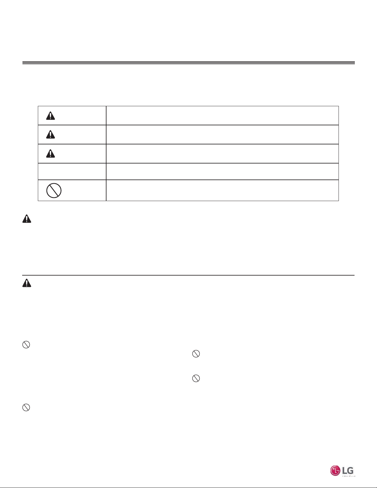
The instructions below must be followed to prevent product malfunction, property damage, injury or death to the user or other people. Incorrect operation due to ignoring any instructions will cause harm or damage. The level of seriousness is classified by the symbols below.
TABLE OF SYMBOLS
This symbol indicates an imminently hazardous situation which, if not avoided, will result in death or
serious injury.
This symbol indicates a potentially hazardous situation which, if not avoided, could result in death or
serious injury.
This symbol indicates a potentially hazardous situation which, if not avoided, may result in minor or
moderate injury.
Note:
Input power to the outdoor unit remains connected and on during procedures in this manual. Do not touch any exposed
outdoor unit wiring, terminals, or other electrical components with tools or exposed skin. Only qualied technicians should
install, use or remove this unit.
Improper installation or use may result in re, explosion, electric shock, physical injury and/or death.
Don’t use or store ammable gas or combustibles near an outdoor or indoor unit.
There is risk of re, explosion, and physical injury or death.
Mobile LGMV
The information in this manual is intended for use by a
trained technician familiar with the U.S. National Electric
Code (NEC) who is equipped with the proper tools and test
instruments.
Failure to carefully read and follow all instructions in this manual may
result in equipment malfunction, property damage, personal injury and/
or death.
Do not install the Mobile LGMV unit if it will be exposed to
rain or other precipitation. Do not install the unit in a location
exposed to open ame or extreme heat. Do not touch the unit
with wet hands.
There is risk of re, electric shock, physical injury and/or death.
For replacement of an installed outdoor or indoor unit,
always contact an LG trained service provider.
There is risk of re, electric shock, explosion, and physical injury or death.
Do not run the compressor with the service valves closed.
There is risk of explosion, physical injury, or death.
Replace all control box and panel covers.
If cover panels are not installed securely, dust, water and animals may
enter the unit, causing re, electric shock, and physical injury or death.
Always check for system refrigerant leaks after an outdoor or
indoor unit has been installed or serviced.
This symbol indicates situations that may result in equipment or property damage accidents only.
This symbol indicates an action that should not be performed.
Exposure to high concentration levels of refrigerant gas may lead to
illness or death.
Wear protective gloves when handling equipment.
Sharp edges may cause personal injury.
Dispose of any packing materials safely.
• Packing materials, such as nails and other metal or wooden parts
may cause puncture wounds or other injuries.
• Tear apart and throw away plastic packaging bags so that children
may not play with them and risk suffocation and death.
Do not install the unit in any location exposed to open
ame or extreme heat. Do not touch the unit with wet hands.
There is risk of re, electric shock, explosion, and physical injury or death.
Do not change the settings of the protection devices.
If the pressure switch, thermal switch, or other protection device is
shorted and forced to operate improperly, or parts other than those
specied by LG are used, there is risk of re, electric shock, explosion,
and physical injury or death.
If the air conditioner is installed in a small space, take measures to prevent the refrigerant concentration from exceeding safety limits in the event of a refrigerant leak.
Consult the latest edition of ASHRAE (American Society of Heating,
Refrigerating, and Air Conditioning Engineers) Standard 15. If the refrigerant leaks and safety limits are exceeded, it could result in personal
injuries or death from oxygen depletion.
4
Due to our policy of continuous product innovation, some specifications may change without notification.
©LG Electronics U.S.A., Inc., Englewood Cliffs, NJ. All rights reserved. “LG” is a registered trademark of LG Corp.
Page 5
SAFETY INSTRUCTIONS
Note:
Always remove the Mobile LGMV wi module when troubleshooting is concluded.
• Random radio frequency signals could cause unintended system
commands to be generated.
• Unauthorized system access is possible.
Mobile LGMV is for use with select LG commercial air conditioning systems only.
with any other type of system. Refer to the compatible equipment list in this manual.
There is risk of equipment damage or degraded performance
Do not cut, lengthen or shorten the cable between the Mobile LGMV unit and the outdoor unit. Do not install the Mobile
LGMV unit in a location where the cable cannot be safely and
easily connected between the two units. Do not allow strain
on this cable.
There is risk of equipment damage.
Clean up the site after all procedures are nished, and check
that no metal scraps, screws, or bits of wiring have been left
inside or surrounding the outdoor or indoor units.
Do not attempt to use Mobile LGMV
Provide power to the outdoor unit compressor crankcase
heaters at least six (6) hours before operation begins.
Starting operation with a cold compressor sump(s) may result in severe
bearing damage to the compressor(s). Keep the power switch on during
the operational season.
Do not block the inlet or outlet.
Unit may malfunction.
Securely attach the electrical cover to the indoor unit. Non-
secured covers can result in re due to dust or water in the
service panel.
Do not allow water, dirt, or animals to enter the unit.
There is risk of unit failure or degraded performance.
Do not spill water or other liquid on the inside of the
outdoor unit, especially on electrical components. Do not
drop the Mobile LGMV unit into water. If the unit is immersed
in water or other liquid, contact your local authorized LG
distributor for support.
There is risk of unit failure or degraded performance.
User Manual
Due to our policy of continuous product innovation, some specifications may change without notification.
©LG Electronics U.S.A., Inc., Englewood Cliffs, NJ. All rights reserved. “LG” is a registered trademark of LG Corp.
5
Page 6

Mobile LGMV Terms and Conditions
In using Mobile LGMV hardware and smart phone application you agree to the Mobile LGMV terms and conditions.
• Mobile LGMV hardware and smart phone application are to be used only with LG Electronics USA, Inc. air
conditioner products.
• Mobile LGMV hardware and smart phone application cannot be sold/transferred/rented to any other parties.
• All data generated by Mobile LGMV hardware and smart phone application cannot be sold/transferred/rented to
any other parties.
• A complete list of Mobile LGMV terms and conditions is on the Mobile LGMV download page at:
http://www.lgeaircon.com/gcac.common.index.dev.
Mobile LGMV
6
Due to our policy of continuous product innovation, some specifications may change without notification.
©LG Electronics U.S.A., Inc., Englewood Cliffs, NJ. All rights reserved. “LG” is a registered trademark of LG Corp.
Page 7
Mobile LG Monitoring View
WARNING
This manual describes how to install and use Mobile LG Monitoring
View (LGMV) to troubleshoot LG commercial air conditioning
equipment.
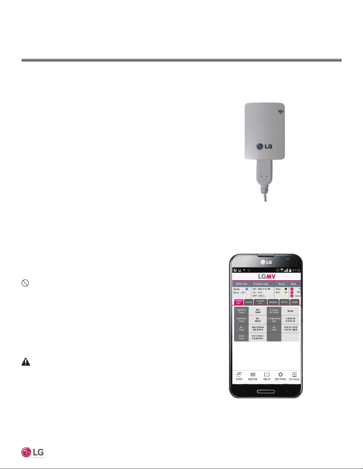
Mobile LGMV consists of:
• a wi module with connecting cable (Figure 1),
Model PLGMVW100
• an app running on an Android device (Figure 2)
(smartphone or tablet)
Compatible Equipment
Mobile LGMV (Android) is compatible with these LG outdoor units:
• Multi V IV Air Heat Pump
• Multi V IV Air Heat Recovery
• Multi V Water IV Heat Pump
• Multi V Water IV Heat Recovery
• Multi V S
• Multi V III Air Heat Pump
• Multi V III Air Heat Recovery
• Multi V Mini
• Multi F/Multi F MAX
Safety
Safety of personnel is the primary concern during all procedures.
Read and understand the safety summary at the front of this manual.
Use the appropriate tools and accessories during troubleshooting.
Do not work alone, if possible. Know how to obtain emergency
medical and fire fighting assistance.
Installation Personnel
This product is intended for use by personnel trained in the required
construction, mechanical, electrical, and/or other disciplines.
Applicable Codes
Personnel must be familiar with and follow the applicable national,
state, and/or local codes.
INTRODUCTION
Figure 1: LGMV Wi Module
User Manual
Figure 2: LGMV App on Smartphone
Troubleshooting work must be performed by trained personnel and in
accordance with national wiring standards and all local or other
applicable codes. Improper troubleshooting and repair/replacement of
equipment can result in re, electric shock, physical injury, or death.
Note:
Improper troubleshooting and repair/replacement of equipment can
result in damaged equipment or degraded operation.
Due to our policy of continuous product innovation, some specifications may change without notification.
©LG Electronics U.S.A., Inc., Englewood Cliffs, NJ. All rights reserved. “LG” is a registered trademark of LG Corp.
7
Page 8
INTRODUCTION
System Conguration
Using LGMV
Mobile LGMV consists of a hardware wifi module, an interface cable, and a free application (app) for Android devices. The user must supply the Android smartphone or tablet.
Before using Mobile LGMV, you must download and install the latest version of the free
app from the LG website listed in this manual.
The wifi module and the smartphone app together provide monitoring and troubleshooting
capability for LG air conditioning systems. Mobile LGMV functions only with LG products.
Mobile LGMV can display and graph operational data for the air conditioner system including
the indoor units and the outdoor unit. Mobile LGMV also displays error codes and a troubleshooting guide (if previously downloaded). Indoor unit operating mode can be set through
Mobile LGMV.
To use Mobile LGMV you must be a trained HVAC service technician familiar with variable refrigerant flow (VRF) systems in general and with LG’s products. You should understand the inverter air conditioning operation cycle, the meaning of the data displayed
by Mobile LGMV, and how to use the data to troubleshoot the system.
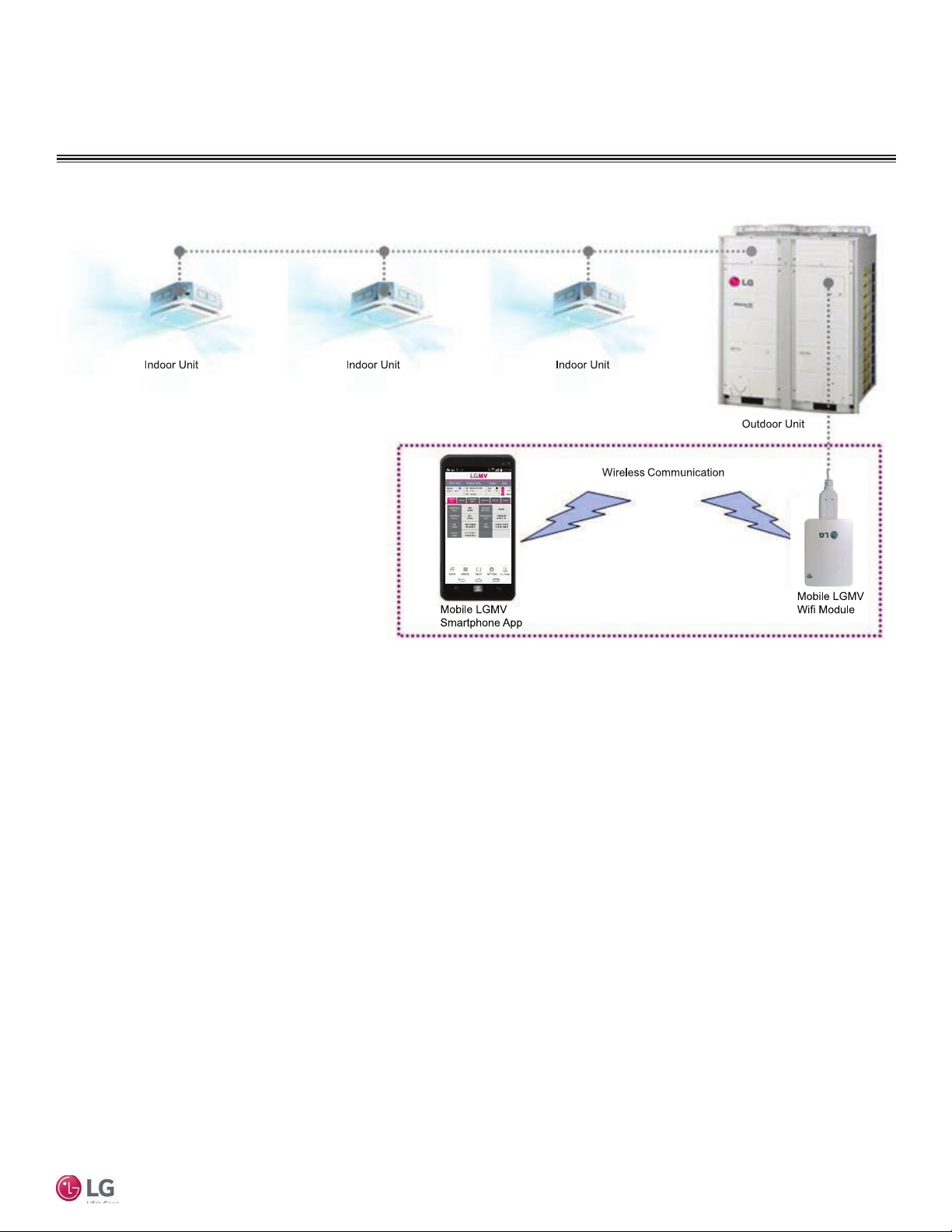
Figure 3 shows the LGMV app and wifi module in a typical troubleshooting application.
The Mobile LGMV wifi module connects to an LG outdoor unit via the supplied cable.
Table 1 lists Mobile LGMV smart phone/tablet requirements.
Note:
• Some functions may not operate or the screen display may be degraded depending on
the smartphone used
• Mobile LGMV will not function normally if the operating environment does not meet the
minimum specifications
Mobile LGMV
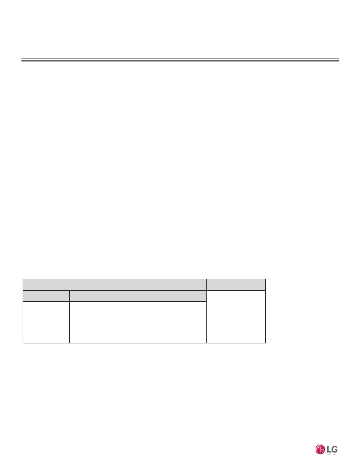
Table 1: Mobile LGMV Smartphone/Tablet Specications
Smartphone/Tablet Specications
Minimum
Specication
• Phone: Android 2.2
• Tablet: Android
4.4.2 (Kitkat)
• CPU: 1 GHz
• RAM 1 GB
• Android 4.4.2 (Kitkat, or higher)
• CPU: 1 GHz dual core, or higher
• CPU: 1 GHz
• 1280 x 720; 800 x 400 resolution
Recommended
(optimized)
Specication
Exceptions
• Android 3.x (Honeycomb)
not supported
• iOS devices not supported
Effective Communication
Distance
• Effective distance: 32.8 ft
(open area)
• Effective distance may
be reduced by the communication environment
8
Due to our policy of continuous product innovation, some specifications may change without notification.
©LG Electronics U.S.A., Inc., Englewood Cliffs, NJ. All rights reserved. “LG” is a registered trademark of LG Corp.
Page 9
INTRODUCTION
Figure 3: Typical Mobile LGMV Troubleshooting Conguration
Mobile LGMV Operating Considerations
• Mobile LGMV processes data in real time. If other functions of the smartphone are
used at the same time as Mobile LGMV, smartphone resources may be insufcient
for Mobile LGMV to process data or the Mobile LGMV connection may be disconnected. Please use the product with this in mind. Always use a smartphone with at
least the minimum recommended specications.
• The Mobile LGMV application may unexpectedly end due to insufcient system
resources.
• Transmission/reception data volume may increase according to the number of indoor
and outdoor units. Mobile LGMV response speed may be slower for some smart-
phone specications.
• Wireless transmission/reception distance may be reduced or communication may be
disconnected due to the operational environment (weather, electromagnetic interference or physical obstacles).
• Mobile LGMV may not work correctly with routed smartphones.
• As communication distance between the Mobile LGMV wifi module and the smart-
phone increases, smartphone wi output may increase, causing greater drain on the
smartphone battery. During use, keep the smartphone as close as safely possible to
the Mobile LGMV wifi module.
• Disconnect the Mobile LGMV wi module from the ODU when troubleshooting is
complete.
User Manual
Due to our policy of continuous product innovation, some specifications may change without notification.
©LG Electronics U.S.A., Inc., Englewood Cliffs, NJ. All rights reserved. “LG” is a registered trademark of LG Corp.
9
Page 10
INTRODUCTION
App User Interface
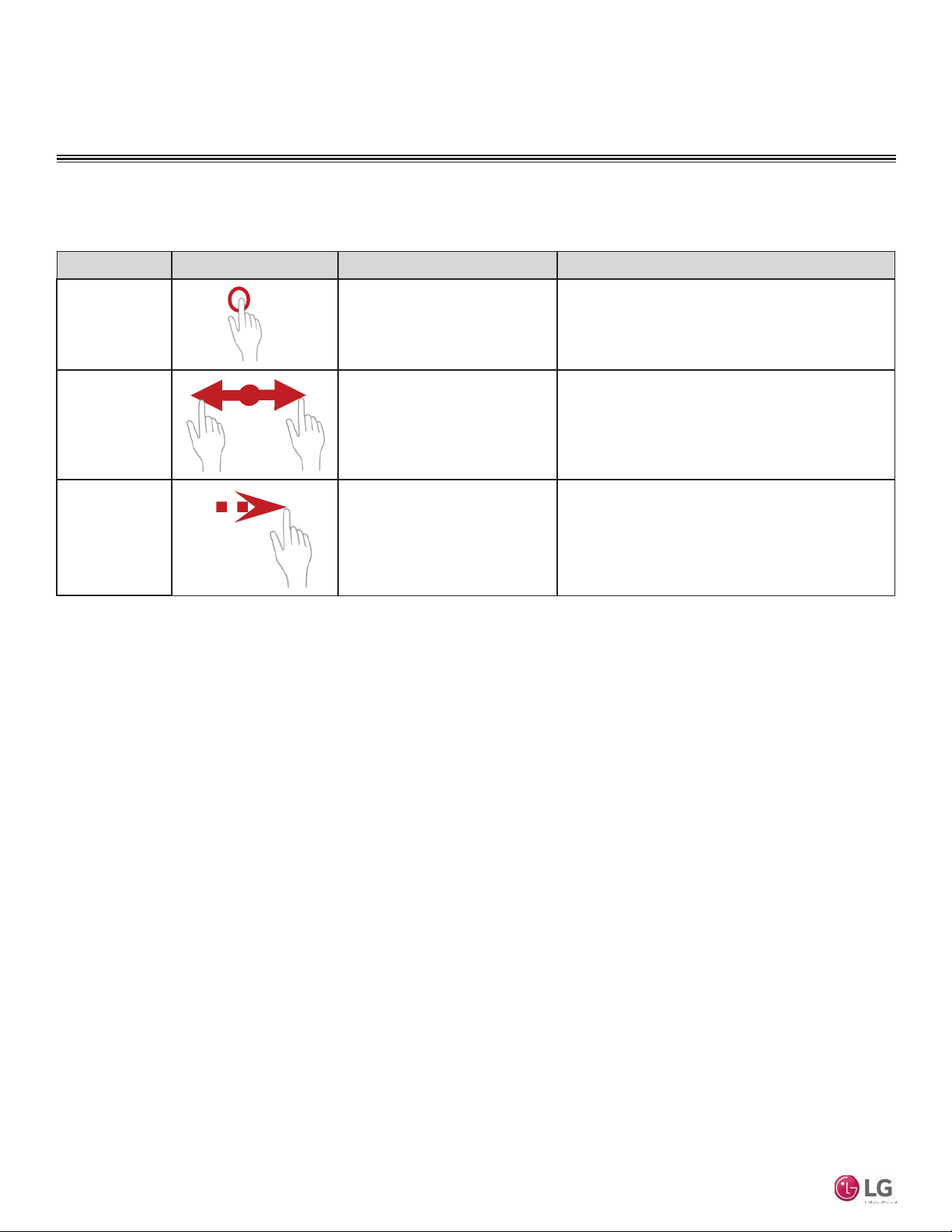
Mobile LGMV uses typical smartphone control gestures to select and display items on screen.
Operation Action Description Result
Tap
(Press)
Pinching
(Tap & Drag)
Flicking
Mobile LGMV
Briefly press the indicated area of
the screen and then release
Operation of pressing two points
on the screen and moving while
keeping pressed
Quickly moving from one point to
another on the screen and then
releasing
1. Press: Applicable object is selected or focused
2. Release: Run event
1. Press: Applicable object is selected or focused
2. Move: Response including moving object/scrolling etc.
3. Release: Stop response or run event
1. Press: No response (Or mark pressed)
2. Quick move & release: Run event
10
Due to our policy of continuous product innovation, some specifications may change without notification.
©LG Electronics U.S.A., Inc., Englewood Cliffs, NJ. All rights reserved. “LG” is a registered trademark of LG Corp.
Page 11
Installation Sequence
To use Mobile LGMV, you must install the app on a smartphone or tablet and you must
connect the wifi module to the outdoor unit. If you have not yet installed the app, it may
be more convenient to do so before arriving at the job site.
Download and Install App
To use Mobile LGMV, you must download and install the
app on an Android device.
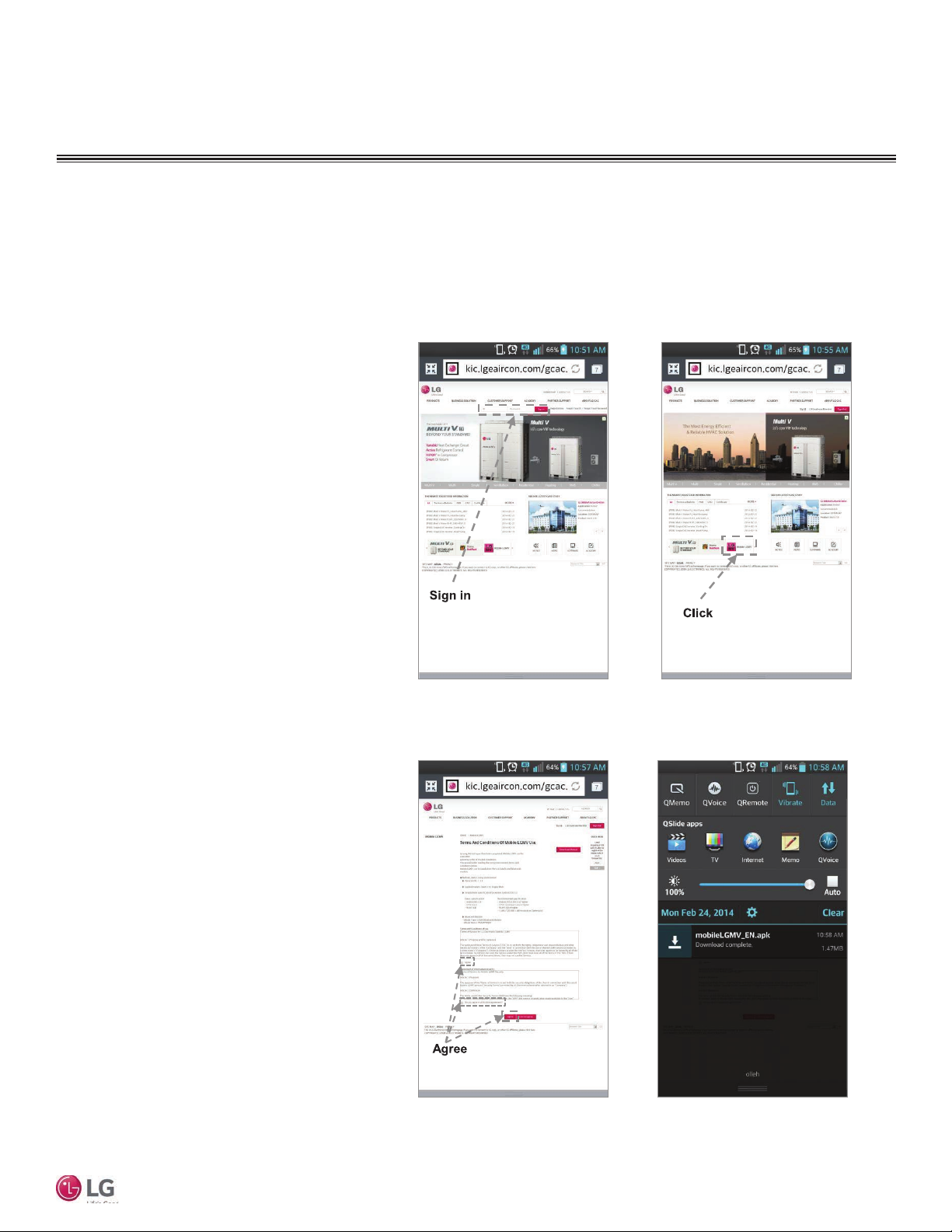
1. Open a web browser on your Android device and go to
http://www.lgeaircon.com/gcac.common.index.dev.
2. Sign in to your account (Figure 4). If you do not have
an account, create a new account.
3. Tap the Mobile LGMV icon (Figure 5). The User
Agreement page is displayed.
4. Read the User Agreement and tap the Agree buttons
to begin the app download (Figure 6).
5. Select the downloaded installation file (.apk) to proceed with installation (Figure 7).
Figure 4:
INSTALLATION
Application Installation
Figure 5:
User Manual
Figure 6: Figure 7:
Due to our policy of continuous product innovation, some specifications may change without notification.
©LG Electronics U.S.A., Inc., Englewood Cliffs, NJ. All rights reserved. “LG” is a registered trademark of LG Corp.
11
Page 12
INSTALLATION
Application Installation
Download and Install App - continued
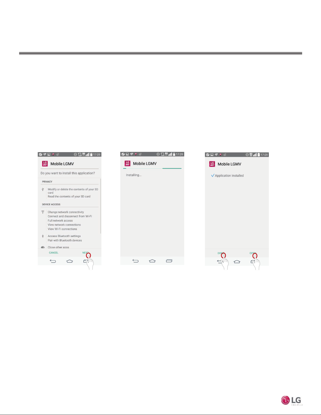
6. Read the app privacy and access information and tap NEXT
(Figure 8).
7. Observe the installation progress screen as the app is installed
(Figure 9).
8. When installation is complete, an Application Installed message
is displayed. Tap Open to run the app or tap DONE to end installation (Figure 10).
Mobile LGMV
Figure 8: Figure 9:
Figure 10:
12
Due to our policy of continuous product innovation, some specifications may change without notification.
©LG Electronics U.S.A., Inc., Englewood Cliffs, NJ. All rights reserved. “LG” is a registered trademark of LG Corp.
Page 13
Update the App
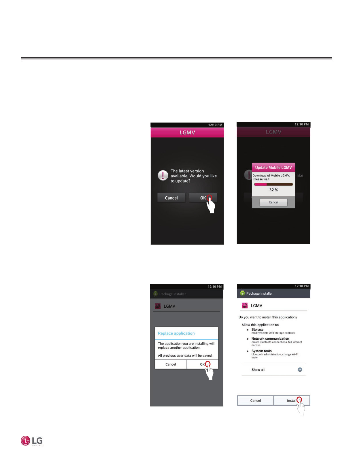
When the app starts, it will check if there is an updated version available.
1. Tap the Mobile LGMV icon to start the app.
2. If there is an app update available, the update
screen displays. Tap OK to start the download
(Figure 11).
3. Observe the download progress on the Update
Mobile LGMV window (Figure 12).
4. When the download finishes, the Replace Application window displays. To acknowledge the existing
application will be replaced, tap OK (Figure 13).
5. Read the application permissions and tap Install
to begin updating the app (Figure 14).
Figure 11:
INSTALLATION
Application Installation
Figure 12:
Figure 13:
User Manual
Figure 14:
Due to our policy of continuous product innovation, some specifications may change without notification.
©LG Electronics U.S.A., Inc., Englewood Cliffs, NJ. All rights reserved. “LG” is a registered trademark of LG Corp.
13
Page 14
INSTALLATION
DANGER
Hardware Installation
Hardware Description
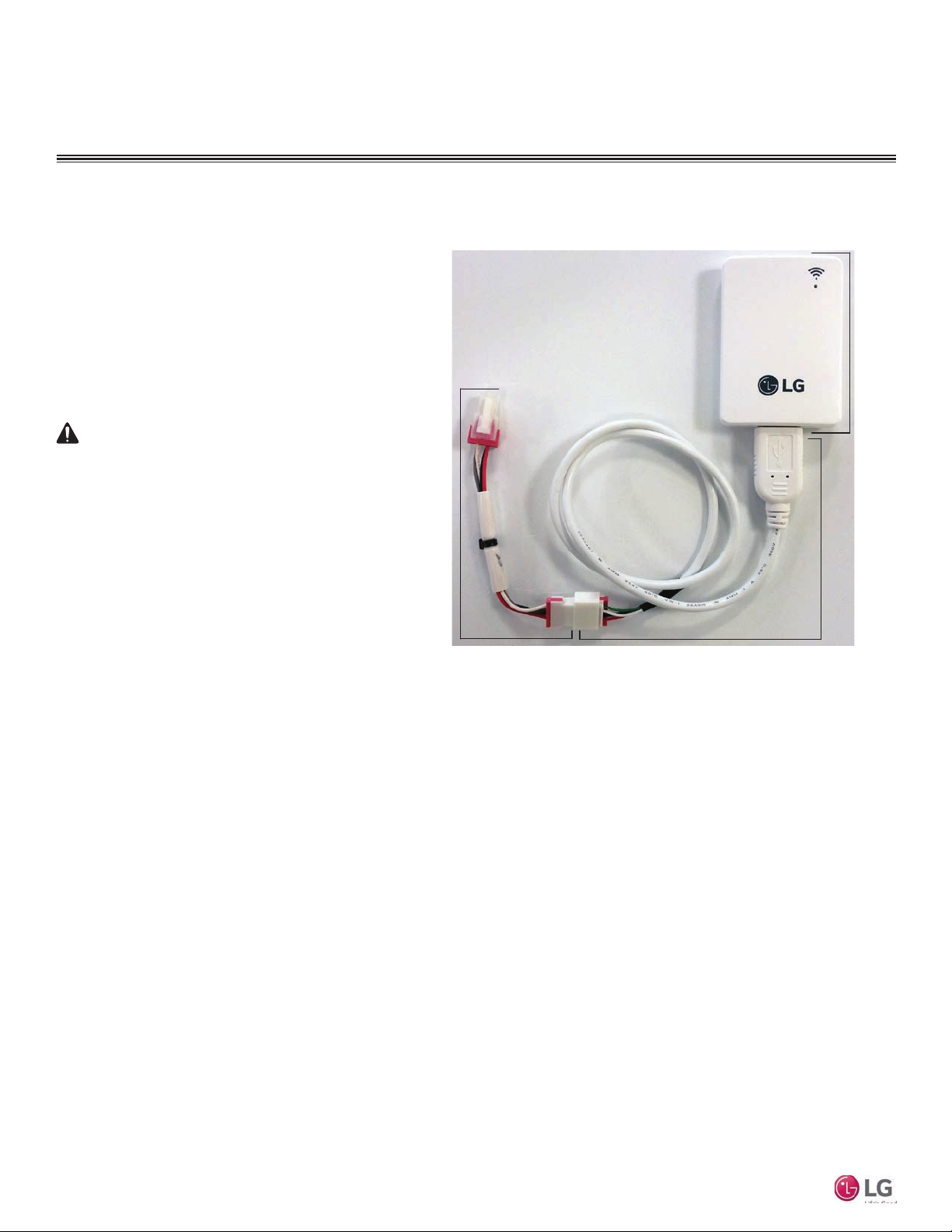
Mobile LGMV hardware consists of a wifi module and a
two-piece cable (Figure 15).
The wifi module sends and receives wifi signals to/from
the smartphone. The cable connects the wifi module to
the outdoor unit. The cable has two sections because
there are two types of outdoor unit connectors, one for
Multi V products and one for Multi F products. When
testing Multi V products, leave the Multi V extension
connected. When testing Multi F products, temporarily
remove the Multi V extension.
Input power to the outdoor unit remains connected and on during this procedure. Do not touch
any exposed outdoor unit wiring, terminals, or
other electrical components with tools or exposed
skin. Only trained technicians should install, use,
or remove this equipment.
Improper installation or use may result in re, explosion,
electric shock, physical injury and/or death.
Multi V
Extension
Cable
Figure 15: Mobile LGMV Wi Module and Cable
Wifi
Module
USB Cable
with Multi F
Connector
Note:
Disconnect the Mobile LGMV wi module from the ODU
when troubleshooting is complete.
Mobile LGMV
Connect Wifi Module
Follow this procedure to connect the Mobile LGMV wifi
module to a Multi V or Multi F outdoor unit.
1. Ensure the latest version of the Mobile LGMV app is
installed on your Android smartphone or tablet.
2. Locate the Mobile LGMV hardware (Figure 15).
3. Connect the wifi module to the USB connector of the
cable.
4. If connecting to a Multi V ODU, ensure the Multi V
extension cable is connected.
5. If connecting to a Multi F ODU, ensure the Multi V
extension cable is not connected. Be sure to retain
the Multi V extension cable.
6. Remove the service panel(s) to gain access to the
interior of the outdoor unit.
7. Locate the Mobile LGMV connector. For Multi V
ODUs, refer to Figure 16. For Multi F ODUs, refer to
Figure 17.
8. Carefully connect the Mobile LGMV cable to the appropriate ODU connector.
9. Place the wifi module and cable in a safe position
where it will not become entangled in other ODU
wiring. Be sure there is clear line of sight between the
wifi module and the Android smartphone or tablet.
14
Due to our policy of continuous product innovation, some specifications may change without notification.
©LG Electronics U.S.A., Inc., Englewood Cliffs, NJ. All rights reserved. “LG” is a registered trademark of LG Corp.
Page 15
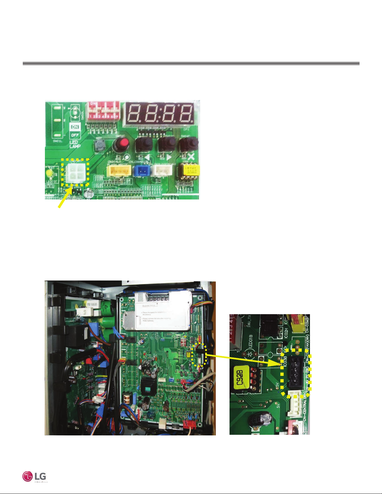
Figure 16: Multi V ODU Connector for Mobile LGMV Cable
INSTALLATION
Hardware Installation
Multi V
Connection
User Manual
Figure 17: Multi F ODU Connector for Mobile LGMV Cable
CN−JIG
Connector
Due to our policy of continuous product innovation, some specifications may change without notification.
©LG Electronics U.S.A., Inc., Englewood Cliffs, NJ. All rights reserved. “LG” is a registered trademark of LG Corp.
15
Page 16
OPERATION
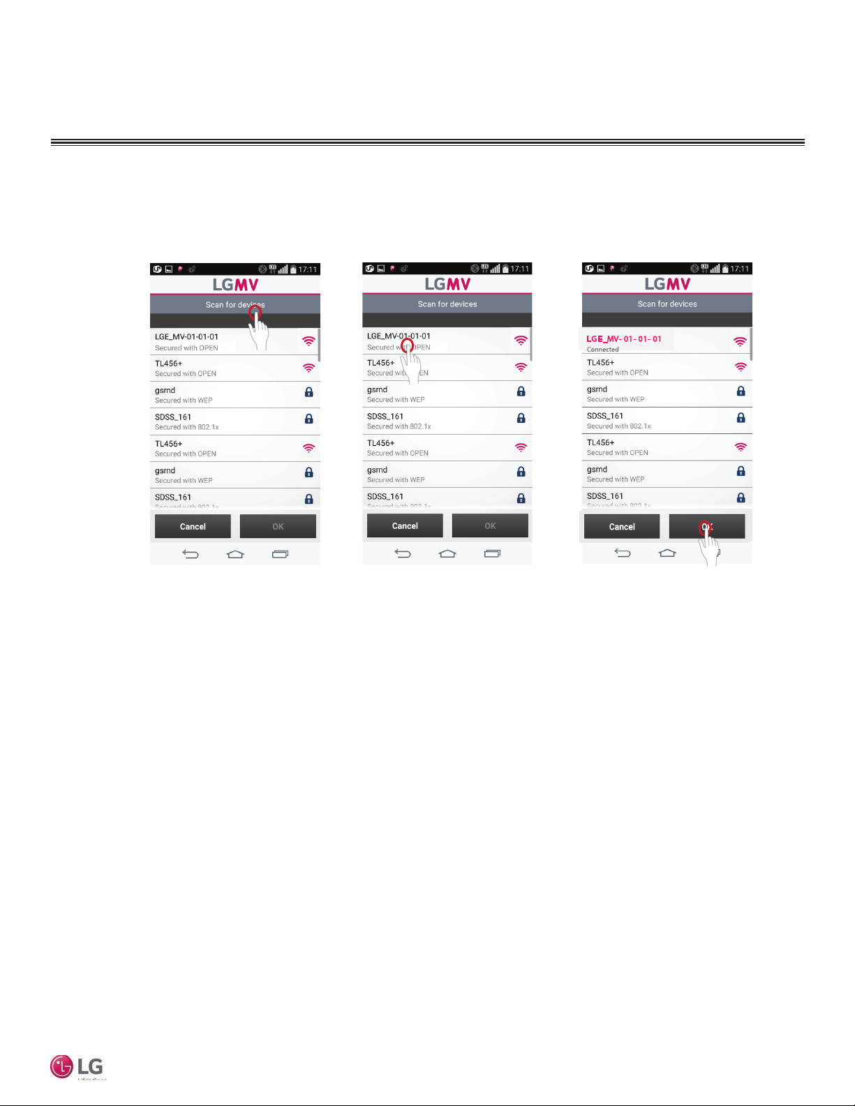
Starting Mobile LGMV
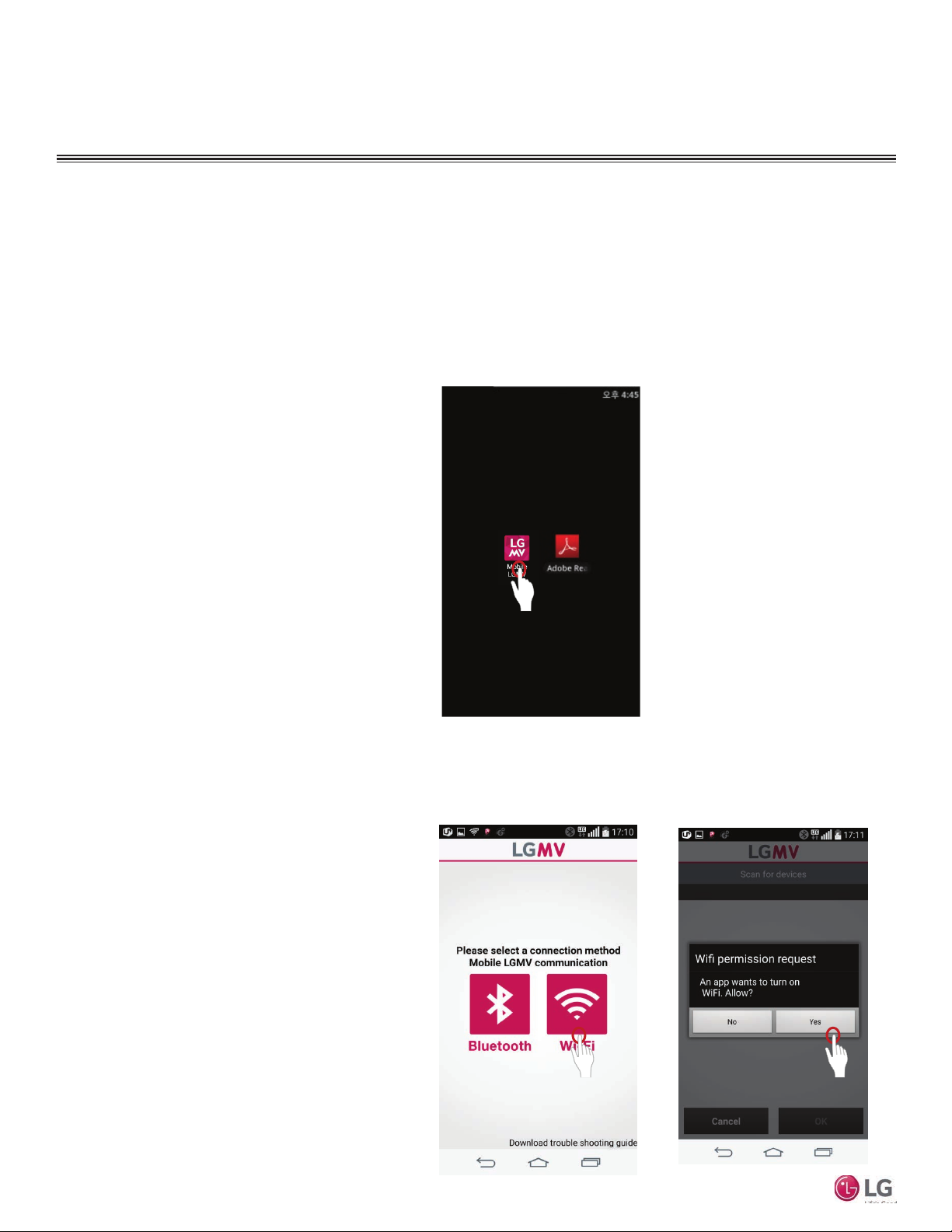
Follow these steps to start the app and connect to the wifi module.
1. Ensure the Mobile LGMV wifi module is correctly connected to
the ODU.
2. Tap the Mobile LGMV icon on your smartphone or tablet to start
the app (Figure 18).
3. Tap the Wi-Fi icon (Figure 19). Bluetooth version is not available
in the US.
4. If necessary, tap Yes to turn on wifi on the device (Figure 20).
5. Tap Scan for Device to search for the wifi module (Figure
21).
6. Tap the device named LG_MV-XX-XX-XX (Figure 22).
7. When connection is made, observe the color of the wifi icon
change (Figure 23).
8. Tap OK to proceed to the monitoring screen (Figure 23).
Figure 18:
Mobile LGMV
Figure 19:
Figure 20:
16
Due to our policy of continuous product innovation, some specifications may change without notification.
©LG Electronics U.S.A., Inc., Englewood Cliffs, NJ. All rights reserved. “LG” is a registered trademark of LG Corp.
Page 17
Starting Mobile LGMV - continued
Figure 21: Figure 22: Figure 23:
OPERATION
User Manual
Due to our policy of continuous product innovation, some specifications may change without notification.
©LG Electronics U.S.A., Inc., Englewood Cliffs, NJ. All rights reserved. “LG” is a registered trademark of LG Corp.
17
Page 18
OPERATION
Configuring Mobile LGMV for ODU
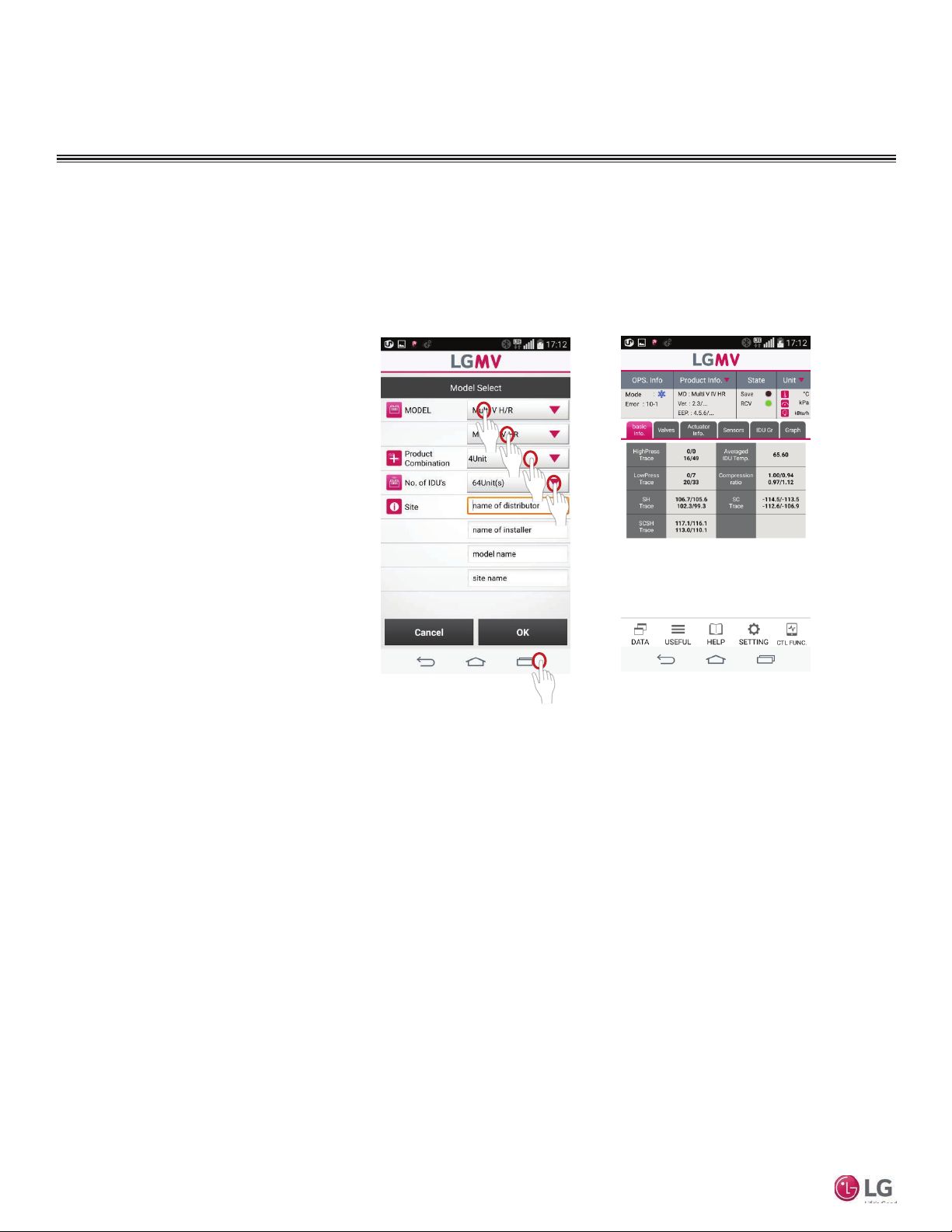
Mobile LGMV must be configured to work with the ODU type you are
testing.
Note:
Mobile LGMV will automatically recognize the following
products: Multi V IV heat pump/heat recovery, Multi V
Water IV heat pump/heat recovery, and Multi V S.
1. Tap to select the ODU model, number of ODU
frames, and number of indoor units (Figure 24).
2. If desired, enter text in the Site fields
(Figure 24).
3. Tap the OK button when finished (Figure 24).
4. The monitoring screen is displayed (Figure 25).
Figure 24:
Figure 25:
Mobile LGMV
18
Due to our policy of continuous product innovation, some specifications may change without notification.
©LG Electronics U.S.A., Inc., Englewood Cliffs, NJ. All rights reserved. “LG” is a registered trademark of LG Corp.
Page 19
OPERATION
Normal Operation and Stopping the App
Note:
Mobile LGMV must receive data for at least 20 minutes before the data is valid for troubleshooting.
Always remove the Mobile LGMV wi module when troubleshooting is concluded.
• Random radio frequency signals could cause unintended system commands to be generated.
• Unauthorized system access is possible.
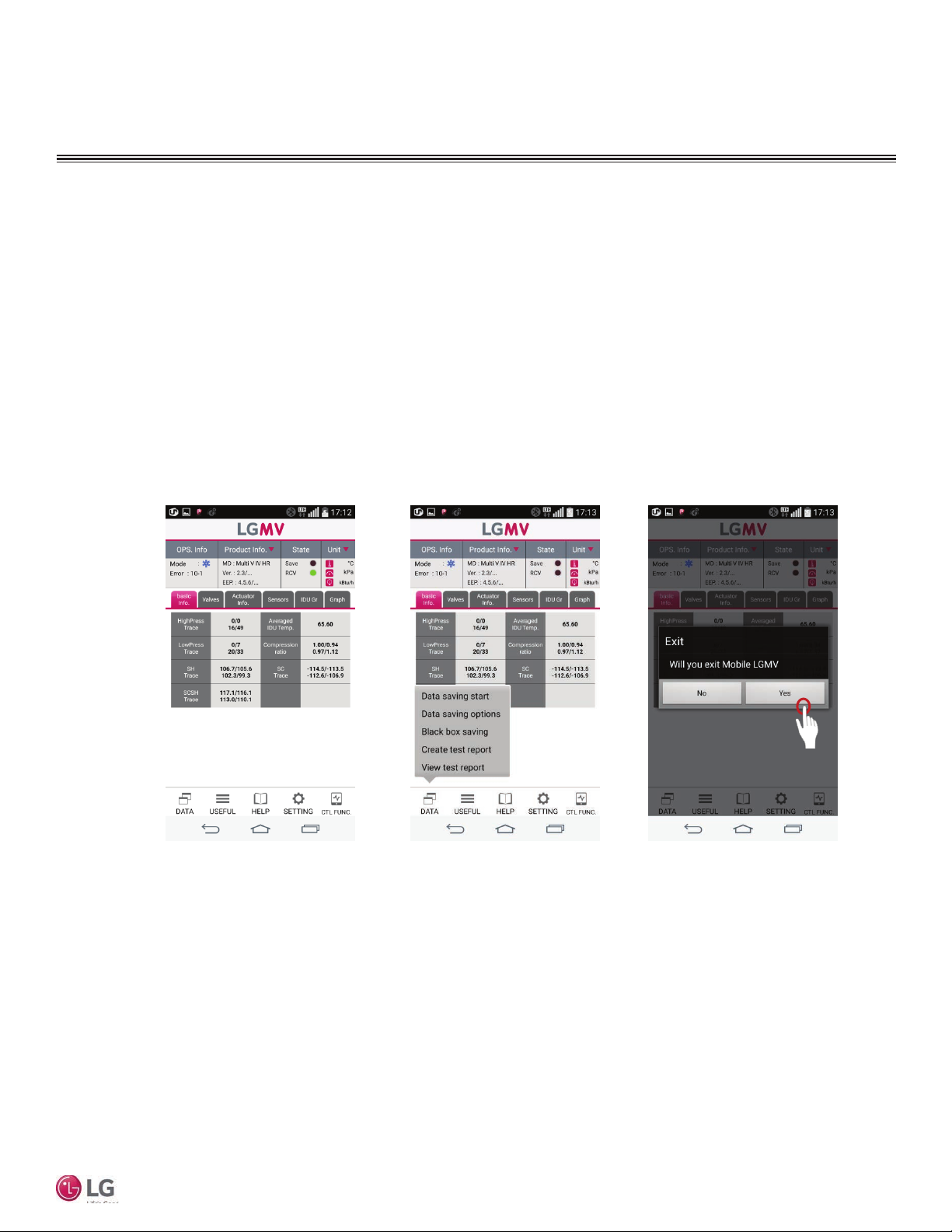
1. Observe the RCV indicator (Figure 26). During normal operation it will be green to indicate a good wifi connection.
2. Refer to the procedures and information on the following pages to troubleshoot the system (Figure 27).
3. When Mobile LGMV operation is concluded, press the Back button on the smartphone to end Mobile LGMV (Figure 28).
4. Disconnect the Mobile LGMV wifi module from the ODU.
5. Clean up any discarded items or other debris resulting from troubleshooting.
6. Reinstall any removed panels on the ODU.
Figure 26: Figure 27: Figure 28:
User Manual
Due to our policy of continuous product innovation, some specifications may change without notification.
©LG Electronics U.S.A., Inc., Englewood Cliffs, NJ. All rights reserved. “LG” is a registered trademark of LG Corp.
19
Page 20
OPERATION
Main Screen
Mobile LGMV Main Screen
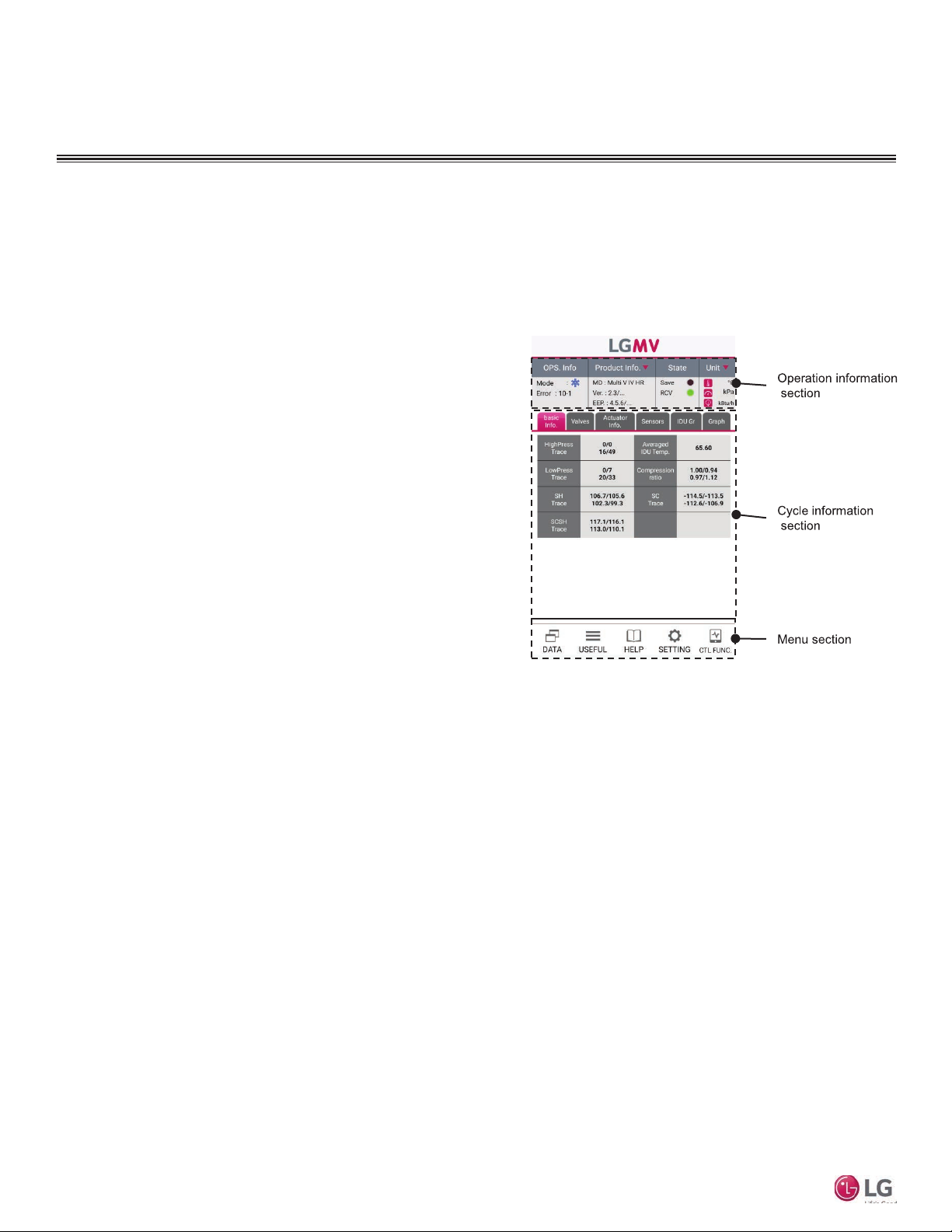
When communication is established between the ODU and the app,
the Mobile LGMV main screen (Figure 29) displays. This screen
displays information about the air conditioning system to which it is
connected. There are three main sections:
• Operation information section: This section displays operating
mode, error information, product information, unit information
etc.
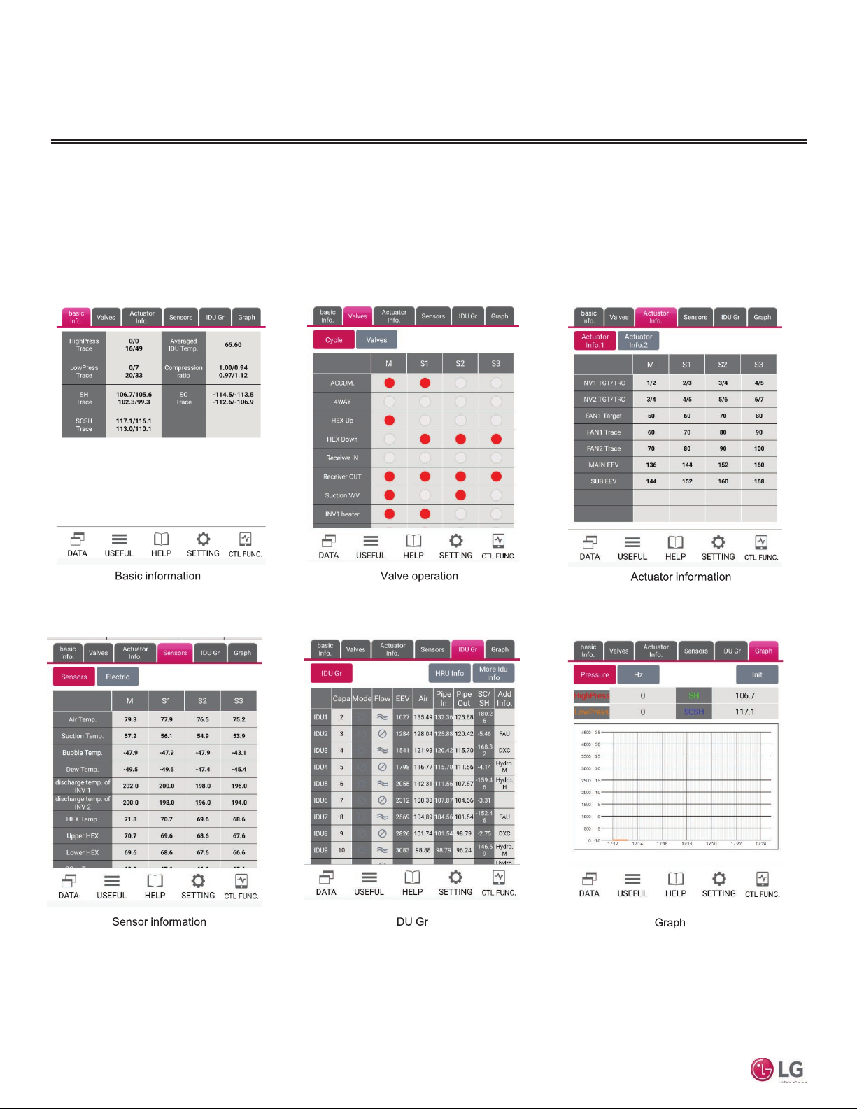
• Cycle information section: Information is divided into tabs. Select
each tab to view basic information, valve operation, actuator
information, sensor information, IDU Gr and graph information.
• Menu section: This section provides additional functions includ-
ing saving air conditioner data, Useful function setting, and
indoor unit operation control etc.
Mobile LGMV
Figure 29:
20
Due to our policy of continuous product innovation, some specifications may change without notification.
©LG Electronics U.S.A., Inc., Englewood Cliffs, NJ. All rights reserved. “LG” is a registered trademark of LG Corp.
Page 21
Main Screen- Operation Information
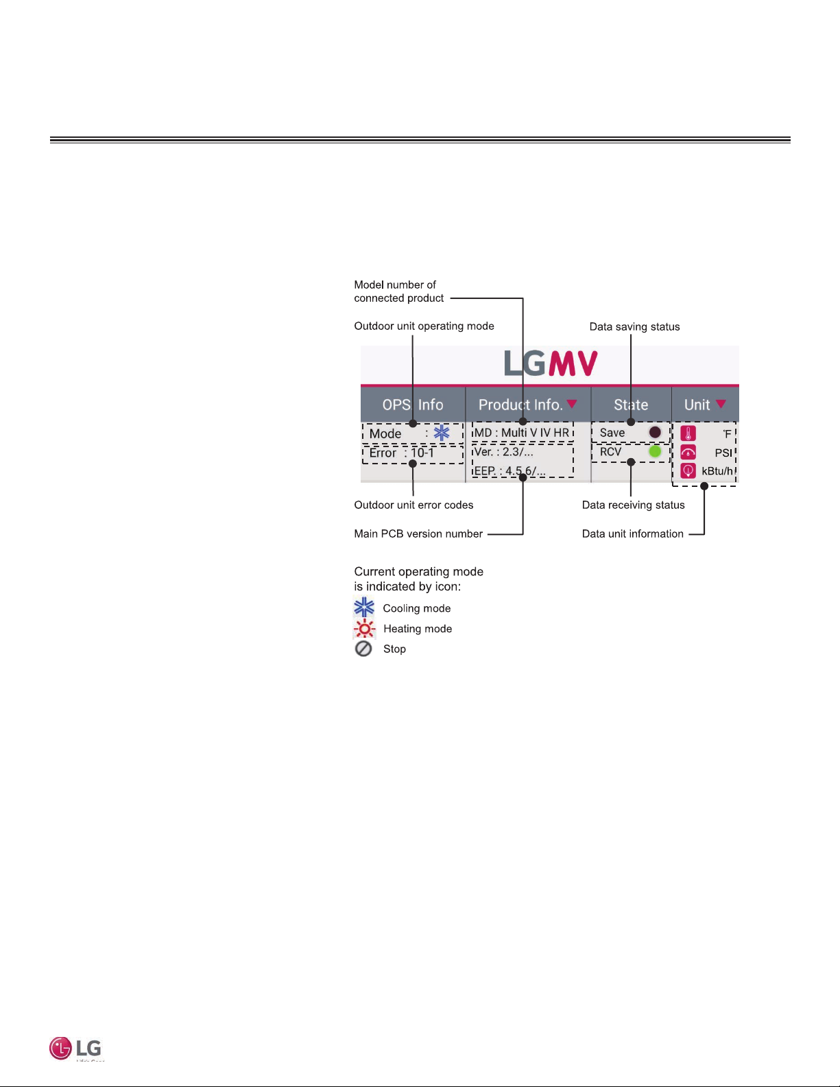
The main screen operation information section (Figure 30) is
described below.
• Outdoor unit operating mode. Displays the current operating
mode of the outdoor unit. It shows cool/heat/fan/stop.
• Outdoor unit error information. Displays the
current ODU error code.
• Connected product model. Displays the model
of outdoor unit connected to Mobile LGMV.
• Main board version information. Displays the
version and EEP information of the connected
outdoor unit.
• Data saving status. Green light is on when data
is being saved.
• Data receiving status. Green light ashes when
data is being received from the outdoor unit.
If there is a communication error, this light
ashes red.
• Data unit information. Displays the units of
measure of displayed data. Either standard or
metric units can be selected for display.
OPERATION
Main Screen
Figure 30:
User Manual
Due to our policy of continuous product innovation, some specifications may change without notification.
©LG Electronics U.S.A., Inc., Englewood Cliffs, NJ. All rights reserved. “LG” is a registered trademark of LG Corp.
21
Page 22
OPERATION
Main Screen
Main Screen- Cycle Information
Cycle information screens are shown below (Figure 31 through Figure 36). Tap the desired section tap heading to display that section’s data. Each of these sections is described on the following pages.
Mobile LGMV
Figure 34:
Figure 31: Figure 32:
Figure 35:
Figure 33:
Figure 36:
22
Due to our policy of continuous product innovation, some specifications may change without notification.
©LG Electronics U.S.A., Inc., Englewood Cliffs, NJ. All rights reserved. “LG” is a registered trademark of LG Corp.
Page 23
OPERATION
Main Screen
Main Screen- Basic Info Tab
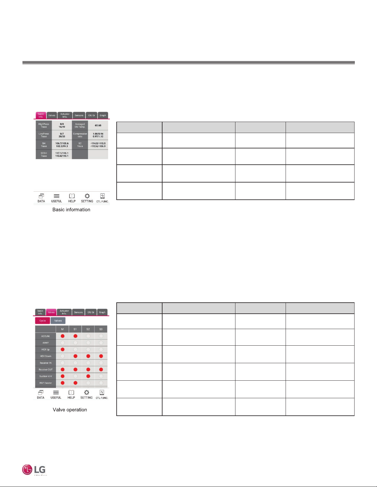
Tap the Basic Info tab on the main screen to display its information (Figure 37). Information displayed will change according to the
connected outdoor unit.
Figure 37:
Name Description Name Description
HighPress Trace Current high pressure Averaged IDU Temp.
LowPress Trace Current low pressure Compression ratio Compression ratio
SH Trace Current degree of super heat SC Trace Current degree of subcooling
Weighted average indoor
temperature
SCSH Trace
Current degree of subcooling
and super heat
Main Screen- Valve Tab
Tap the Valves tab on the main screen to display its information (Figure 38). This information is presented in two subscreens, Cycle
and Valves.
Figure 38:
Name Description Name Description
ACCUM. Oil return valve VI Vapor Injection
4 WAY 4 WAY valve INV1 heater Inverter 1 heater
HEX Up Heat exchanger top valve INV2 heater Inverter 2 heater
User Manual
HEX Down Heat exchanger bottom valve HEX V/V Heat exchanger valve
Receiver IN Normal Close Valve OIL LEVEL1 Oil level 1
Receiver OUT Normal Open Valve OIL LEVEL2 Oil level 2
Due to our policy of continuous product innovation, some specifications may change without notification.
©LG Electronics U.S.A., Inc., Englewood Cliffs, NJ. All rights reserved. “LG” is a registered trademark of LG Corp.
23
Page 24
OPERATION
Main Screen
Main Screen- Actuator Info Tab
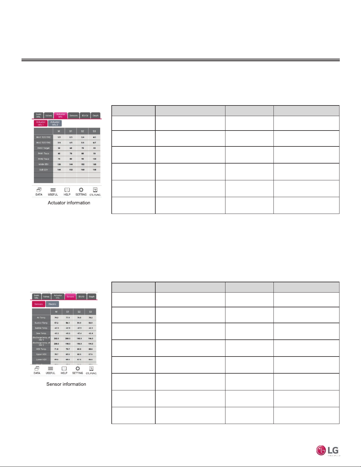
The Actuator Info tab (Figure 39) displays operating parameters of various devices (compressors, fans, EEVs) in each outdoor unit
frame. This information is displayed in two screens, Actuator Info 1 and Actuator Info 2.
Figure 39:
Name Description Name Description
INV1 TGT/TRC
INV2 TGT/TRC
FAN Target FAN target RPM SC EEV Subcooling EEV
FAN1 Trace FAN1 current RPM EQ EEV Oil supply EEV
FAN2 Trace FAN2 current RPM VI EEV1 Vapor Injection EEV1
Inverter 1 target/current
frequency
Inverter 2 target/current
frequency
MAIN EEV Main EEV
SUB EEV Sub EEV
VI EEV2 Vapor Injection EEV2
Main Screen- Sensors Tab/Sensors
The Sensors tab has two screens, Sensors and Electric. Tap the Sensors tab at the top of the main screen and then tap the
Sensors tab below it. The screen displays the sensors data (Figure 40).
Mobile LGMV
24
Figure 40:
Name Description Name Description
Air Temp. Outdoor air temperature Lower HEX
Suction Temp. Compressor suction temperature SC in Temp. Subcooling inlet temperature
Bubble Temp. Condenser temperature SC out Temp. Subcooling outlet temperature
Dew Temp. Evaporator temperature Liquid Temp. Liquid pipe temperature
discharge temp. of
INV1
discharge temp. of
INV1
HEX Temp.
Upper HEX
Due to our policy of continuous product innovation, some specifications may change without notification.
©LG Electronics U.S.A., Inc., Englewood Cliffs, NJ. All rights reserved. “LG” is a registered trademark of LG Corp.
Inverter 1 discharge temperature INV1 IPM Temp Inverter 1 IPM temperature
Inverter 2 discharge temperature INV2 IPM Temp Inverter 2 IPM temperature
Heat exchanger pipe
temperature
Top heat exchanger pipe
temperature
FAN Heatsink
Bottom heat exchanger pipe
temperature
Outdoor fan heat sink
temperature
Page 25
OPERATION
Main Screen
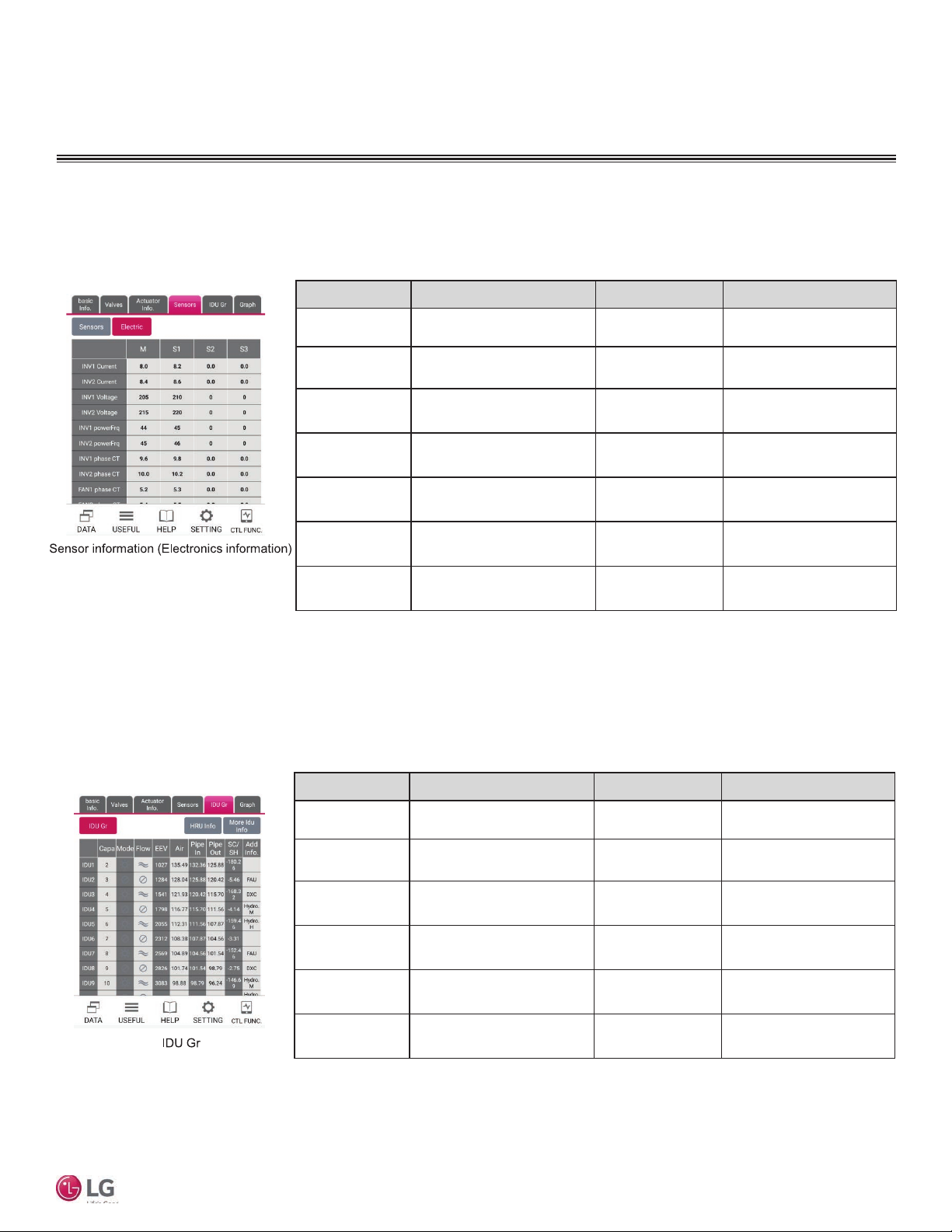
Main Screen- Sensors Tab/Electric
The Sensors tab has two screens, Sensors and Electric. Tap the Sensors tab at the top of the main screen and then tap the Electric
tab below it. The screen displays the electric data (Figure 41).
Figure 41:
Name Description Name Description
INV1 Current Inverter 1 input current INV1 phase CT Inverter 1 phase current
INV2 Current Inverter 2 input current INV2 phase CT Inverter 2 phase current
INV1 Voltage Inverter 1 input voltage FAN1 phase CT Fan1 phase current
INV2 Voltage Inverter 2 input voltage FAN2 phase CT Fan 2 phase current
INV1 powerFrq Inverter 1 power frequency FAN DC link Fan DC LINK voltage
INV2 powerFrq Inverter 2 power frequency INV1 DC link Inverter 1 DC LINK voltage
INV2 DC link Inverter 2 DC LINK voltage
Main Screen - IDU Gr
The IDU Gr tab has three screens, IDU Gr, HRU Info, and More IDU Info (Figure 42). Tap the IDU Gr tab at the top of the main
screen and then tap the IDU Gr, HRU Info, or More IDU Info tab below it. The screen displays the selected data.
User Manual
Figure 42:
Name Description Name Description
Capa Indoor unit capacity Pipe Out Indoor pipe outlet temperature
Mode Indoor unit operating mode SC/SH
Flow Indoor unit fan level Add Info. Indoor unit type information
EEV Indoor unit EEV Comm Communication rate
Air Indoor air temperature CEN Central control address
Pipe In Indoor pipe inlet temperature Error Indoor unit error number
Due to our policy of continuous product innovation, some specifications may change without notification.
©LG Electronics U.S.A., Inc., Englewood Cliffs, NJ. All rights reserved. “LG” is a registered trademark of LG Corp.
Degree of Subcooling/super
heat
25
Page 26
OPERATION
Main Screen
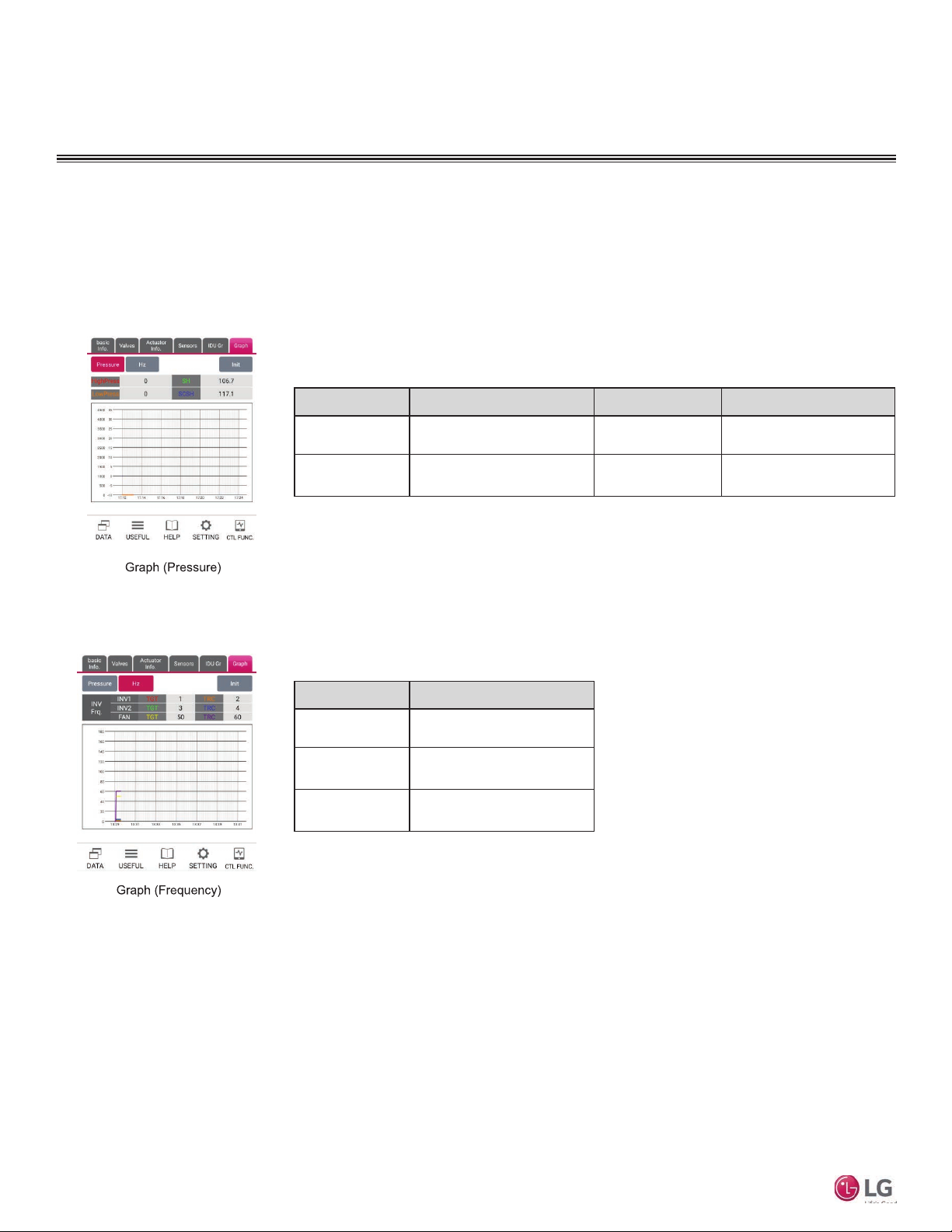
Main Screen - Graph
The Graph tab has two screens, Pressure and Hz (frequency). Tap the Graph tab at the top of the main screen and then tap the
Pressure (Figure 43) or Hz (Figure 44) tab below it. The screen begins to graph the selected data.
Figure 43:
Name Description Name Description
HighPress. Current high pressure SH
LowPress. Current low pressure SCSH
Current degree of super
heating
Current degree of super
cooling/heating
Figure 44:
Mobile LGMV
Name Description
INV1 Inverter 1 frequency
INV2 Inverter 2 frequency
FAN FAN RPM
26
Due to our policy of continuous product innovation, some specifications may change without notification.
©LG Electronics U.S.A., Inc., Englewood Cliffs, NJ. All rights reserved. “LG” is a registered trademark of LG Corp.
Page 27
OPERATION
Gr Displays
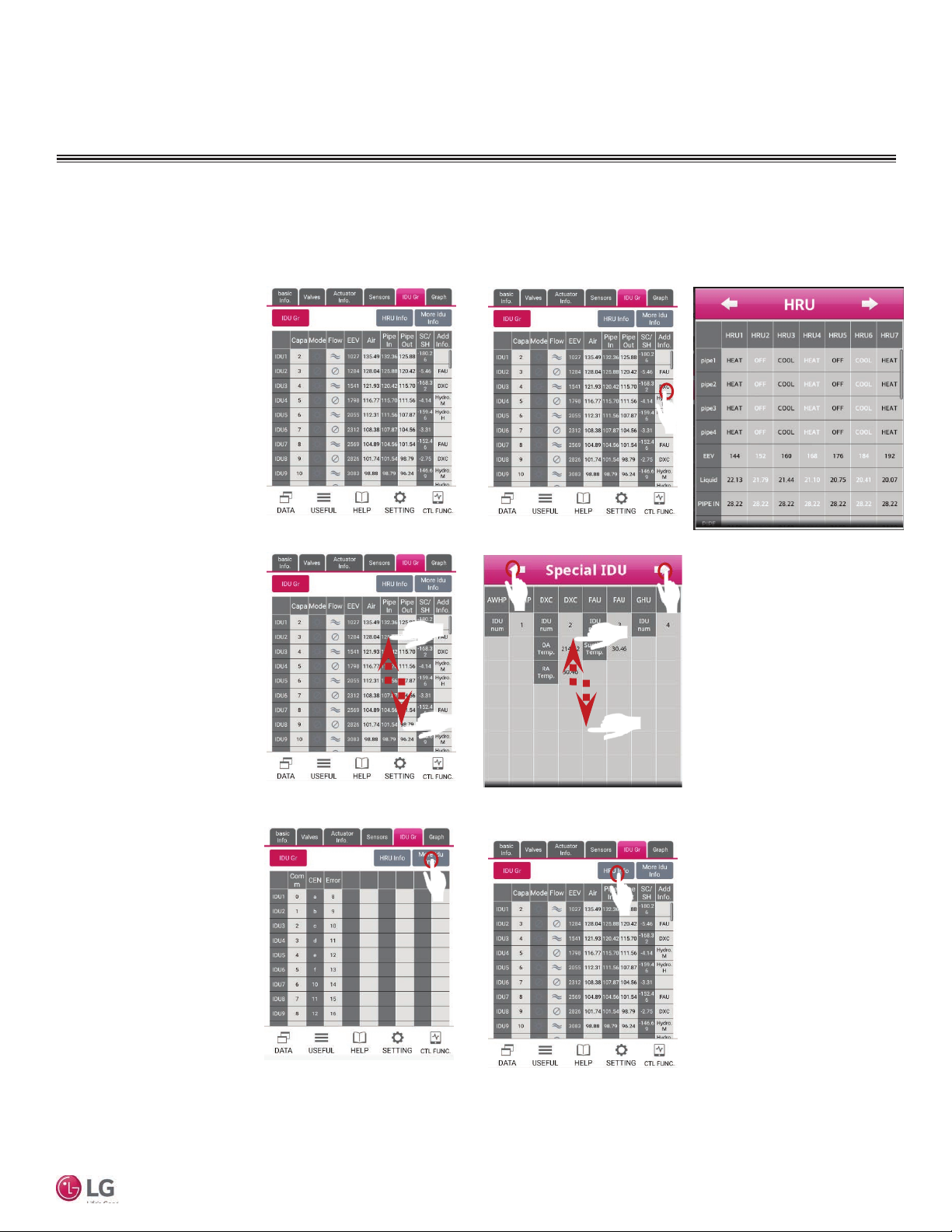
How to use IDU Gr Displays
The IDU Gr displays show operating data for the indoor units connected to the monitored system. These steps are an example of
selecting screens and displaying data.
1. Tap the IDU Gr tab
(Figure 45). Indoor unit data
is displayed.
2. Flick up/down through the
IDU list to find the information of any particular IDU
(Figure 48).
3. Tap the More IDU Info button
to display additional data for
that IDU (Figure 50).
4. If desired, tap the More IDU
data to display the Special
IDU data screen.
5. Special IDU information is
displayed by IDU type. You
can tap the arrows at the top
of the screen to move to the
previous or next IDU on the
list (Figure 49).
6. If desired, tap the HRU
button (Figure 50) to display
heat recovery unit data (heat
recovery systems only).
7. The HRU screen displays
data for each heat recovery
unit. You can tap the arrows
at the top of the screen
(Figure 47) to move to the
previous or next HRU on the
list (heat recovery systems
only).
Figure 45:
Figure 48:
Figure 50:
Figure 46:
Figure 49:
Figure 51:
Figure 47:
User Manual
Due to our policy of continuous product innovation, some specifications may change without notification.
©LG Electronics U.S.A., Inc., Englewood Cliffs, NJ. All rights reserved. “LG” is a registered trademark of LG Corp.
27
Page 28
OPERATION
Data Menu
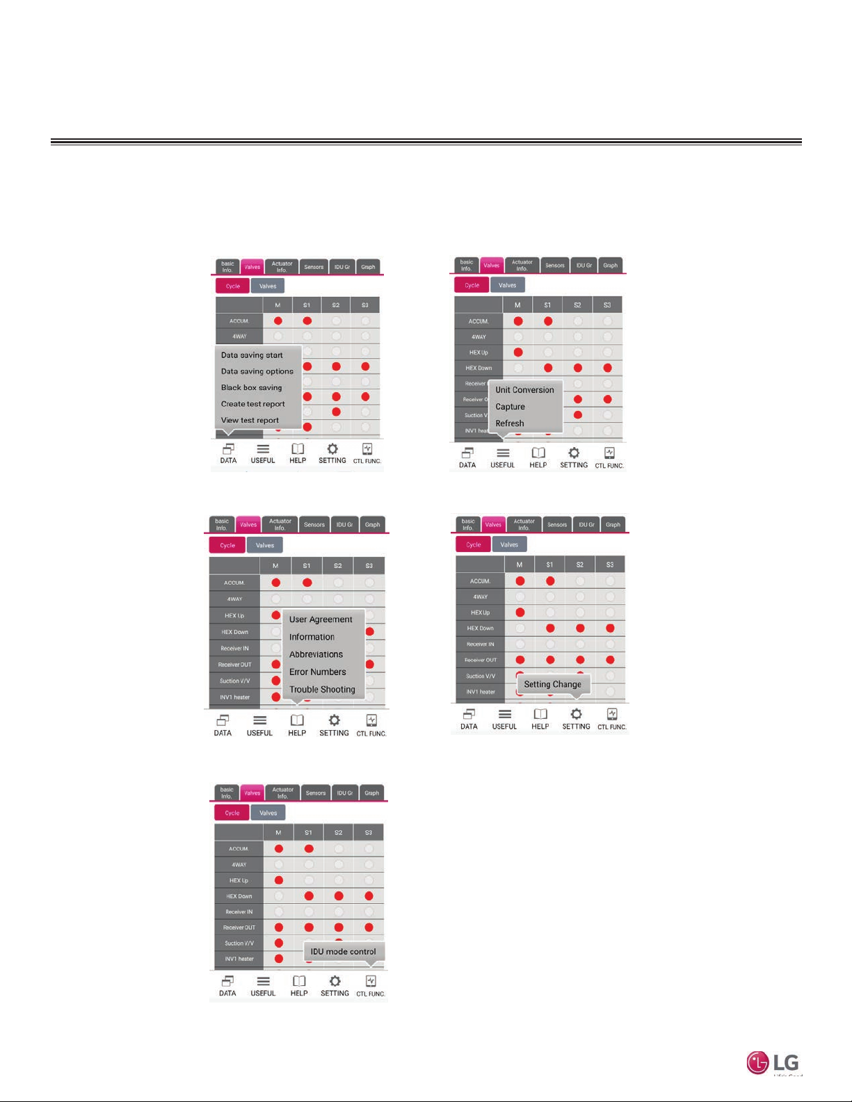
Popup Menu Selections
The buttons along the bottom of the screen display popup menus with additional command choices. The buttons are DATA (Figure 52),
USEFUL (Figure 53), HELP (Figure 54), SETTING (Figure 55), and CTL FUNC (Figure 56).
Mobile LGMV
Figure 52:
Figure 54:
Figure 53:
Figure 55:
28
Figure 56:
Due to our policy of continuous product innovation, some specifications may change without notification.
©LG Electronics U.S.A., Inc., Englewood Cliffs, NJ. All rights reserved. “LG” is a registered trademark of LG Corp.
Page 29
OPERATION
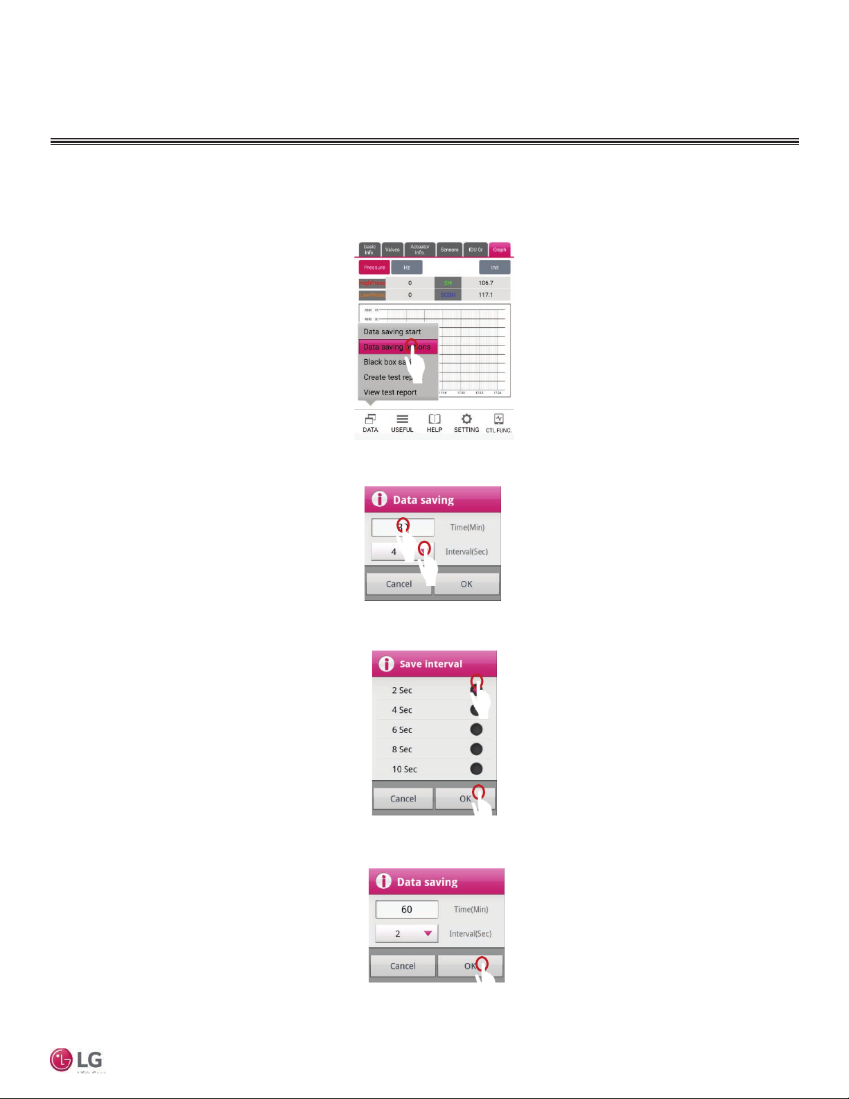
Data Menu
Saving Data
You have the option of saving the data that Mobile LGMV displays. The default data saving parameters are 60 minutes at an interval
of 2 seconds.
Figure 57:
1. Tap the DATA button at the bottom
of the screen. On the popup menu,
tap Data Saving Options
(Figure 57).
2. The Data saving options window
displays. Enter the time in minutes
to save data (Figure 58).
3. To change the time interval for
saving data, tap the Interval(Sec)
button (Figure 58).
4. The Save interval window displays.
Tap the desired time interval and
then tap OK (Figure 59).
5. The Data saving window displays
again. Confirm the time and interval
are as desired and tap the OK
button (Figure 60).
Figure 58:
User Manual
Figure 59:
Figure 60:
Due to our policy of continuous product innovation, some specifications may change without notification.
©LG Electronics U.S.A., Inc., Englewood Cliffs, NJ. All rights reserved. “LG” is a registered trademark of LG Corp.
29
Page 30
OPERATION
Data Menu
Starting the Data Save
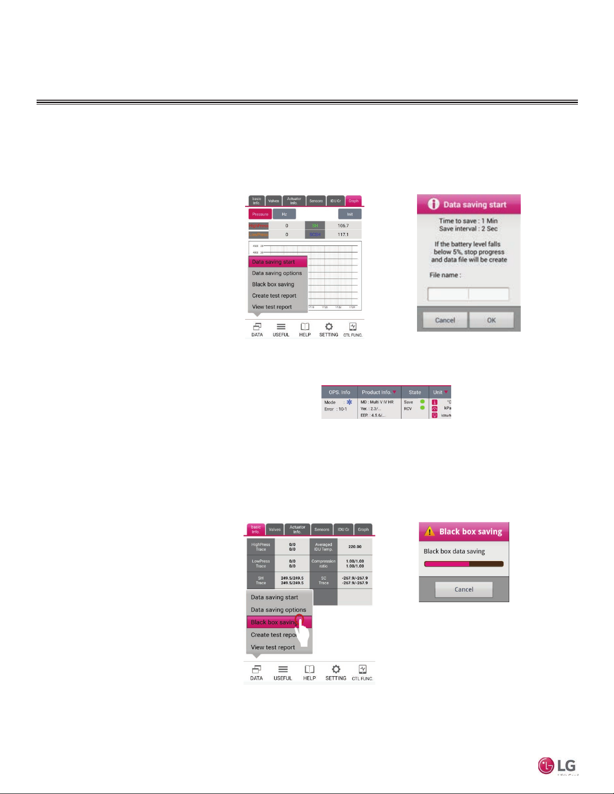
Before starting to save data, set the duration and interval as described in Saving Data on page 29. Follow this procedure to begin
the capturing of data and saving data to a file on the smartphone. The default folder for saved data files is LGMV>Data. Data files
captured by Mobile LGMV can be transferred to a personal computer with the PC version of LGMV, if desired.
1. Tap the DATA button at the bottom of
the screen. On the popup menu, tap
Data Saving Options (Figure 61).
2. The Data saving options window displays. Enter the duration in minutes to
save data and tap OK (Figure 62).
3. To change the time interval for saving data, tap DATA , then tap Data
saving options, and then tap the
Interval(Sec) button.
4. The Save interval window displays.
Tap the desired time interval and then
tap OK.
5. The Data saving window displays
again. Confirm the time and interval
are as desired and tap the OK button. The SAVE indicator lights green
(Figure 63).
Figure 61:
Figure 63:
Figure 62:
Mobile LGMV
Black Box Data Saving
There is the option to perform Black box data saving. ODU models supporting this function are Multi V IV heat pump and heat recovery, Multi V Water IV heat pump and heat recovery, Multi V III heat pump and heat recovery, and Multi V S. The default folder for
saved files is LGMV>BlackBoxData.
1. Tap the DATA button at the bottom
Figure 64:
of the screen. On the popup menu,
tap Black box saving (Figure 64).
2. The Black box saving window displays. A progress bar indicates the
data is being saved (Figure 65).
Figure 65:
30
Due to our policy of continuous product innovation, some specifications may change without notification.
©LG Electronics U.S.A., Inc., Englewood Cliffs, NJ. All rights reserved. “LG” is a registered trademark of LG Corp.
Page 31
OPERATION
Data Menu
Create Test Report
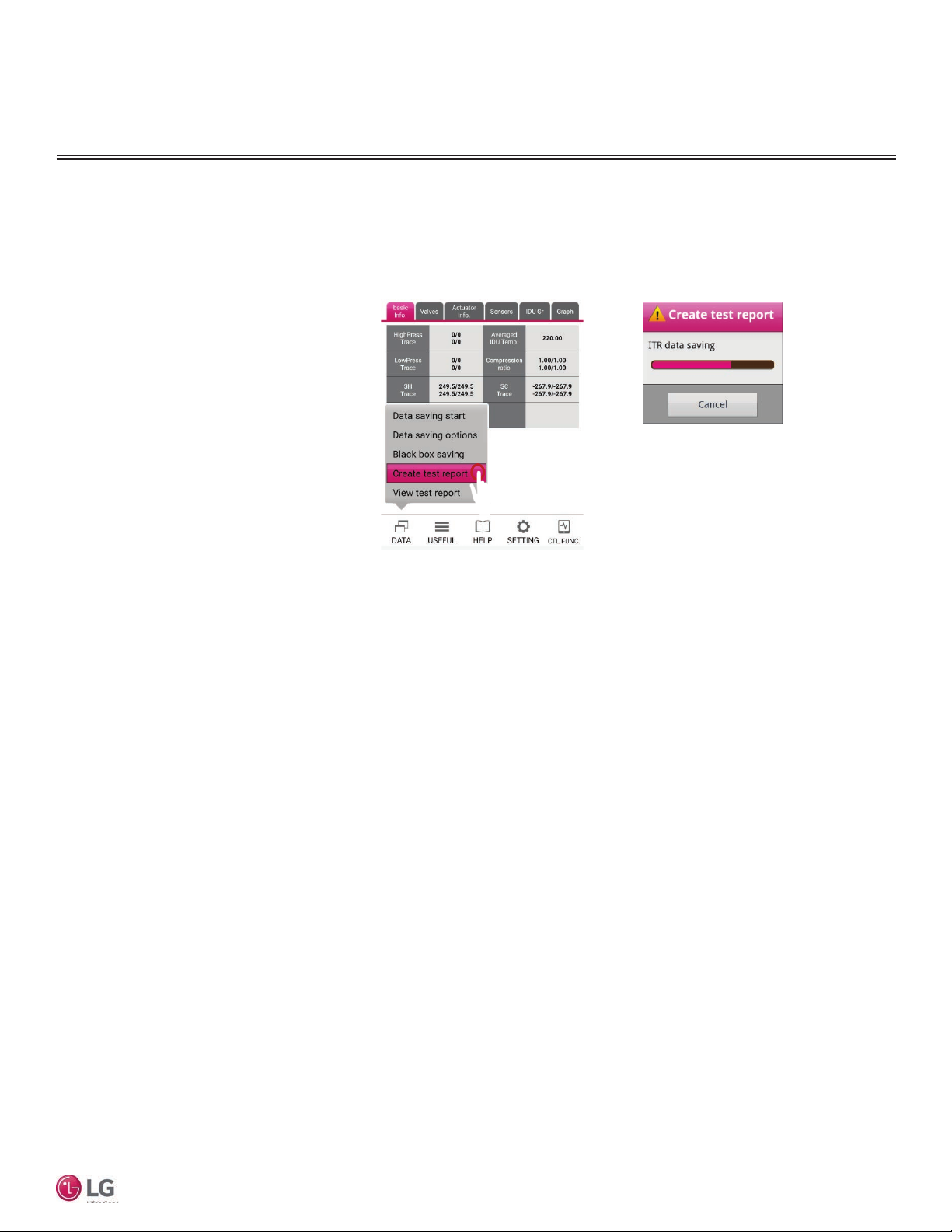
There is the option to create a test report. ODU models supporting this function are Multi V IV heat pump and heat recovery, and
Multi V III heat pump and heat recovery. The default folder for saved files is LGMV>ITRData.
1. Tap the DATA button at the bottom of
the screen. On the popup menu, tap
Create test report (Figure 66).
2. The Create test report saving window
displays. A progress bar indicates the
ITR data is being saved (Figure 67).
Figure 66:
Figure 67:
User Manual
Due to our policy of continuous product innovation, some specifications may change without notification.
©LG Electronics U.S.A., Inc., Englewood Cliffs, NJ. All rights reserved. “LG” is a registered trademark of LG Corp.
31
Page 32
OPERATION
Data Menu
View Test Report
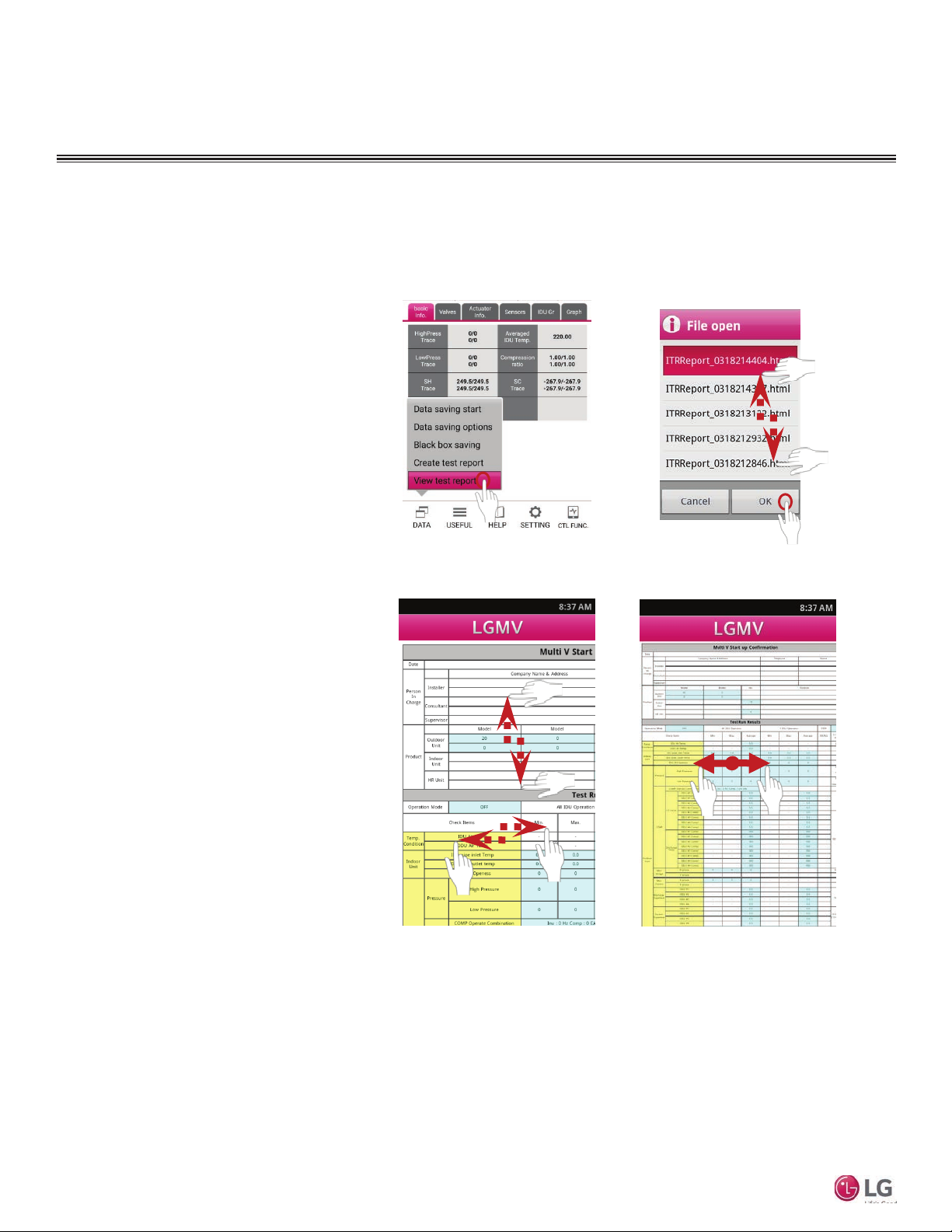
There is the option to view a test report. The default folder for saved test report files is LGMV>ITRData.
1. Tap the DATA button at the bottom of
the screen. On the popup menu, tap
View test report (Figure 68).
2. The File open window displays showing all previously saved test reports.
If necessary, flick up and down the
list to display all report files. Tap the
desired report file name and then tap
OK (Figure 69).
3. The test report displays. Flick up,
down, left, and/or right to display all
areas of the report (Figure 70).
4. If desired, use two fingers to “pinch”
in or out to zoom the display magnification (Figure 71). You can also use
the Add/Remove button at the bottom
right to zoom in or out.
Mobile LGMV
Figure 68:
Figure 70:
Figure 69:
Figure 71:
32
Due to our policy of continuous product innovation, some specifications may change without notification.
©LG Electronics U.S.A., Inc., Englewood Cliffs, NJ. All rights reserved. “LG” is a registered trademark of LG Corp.
Page 33
OPERATION
Useful Menu
Unit Conversion
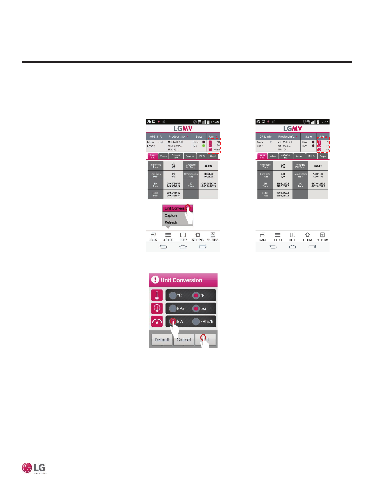
The USEFUL popup menu contains options for setting data units, capturing smartphone screenshots, and refreshing the data display
on the smartphone.
1. To select the unit of measure for
displayed data, tap USEFUL. The
USEFUL popup menu displays
(Figure 72).
2. Tap Unit Conversion. The Unit
Conversion window displays
(Figure 74).
3. Tap the desired unit of measure for
temperature (°C or °F), pressure
(kPa or psi), and unit capacity (kW
or kBtu/h) (Figure 74).
4. When unit selection is complete,
tap SET (Figure 74).
5. Observe the units displayed in the
top right of the screen change to
the selected units (Figure 73). The
data units of all data displayed
on screen change to the selected
units.
Figure 72:
Figure 74:
Figure 73:
User Manual
Due to our policy of continuous product innovation, some specifications may change without notification.
©LG Electronics U.S.A., Inc., Englewood Cliffs, NJ. All rights reserved. “LG” is a registered trademark of LG Corp.
33
Page 34
OPERATION
Useful Menu
Capture
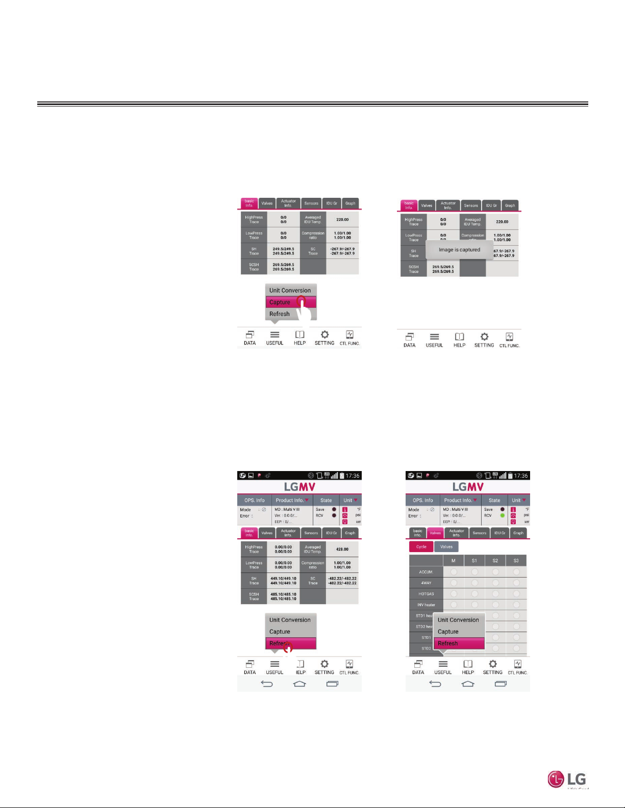
Use the Capture command on the USEFUL popup to capture the smartphone screen display to a graphics file. The capture files are
saved in the LGMV>Capture folder.
Figure 75:
1. To capture the current smartphone
display tap USEFUL. The USEFUL
popup menu displays (Figure 75).
2. Tap Capture. The current smartphone screen display is saved in a
graphics file. The capture is complete when the Image is captured
popup message is displayed
(Figure 76).
Refresh
Use the Refresh command on the USEFUL popup to refresh the smartphone’s data display.
Mobile LGMV
Figure 77:
1. To refresh the data display, tap
USEFUL. The USEFUL popup
menu displays (Figure 77).
2. Tap Refresh. The smartphone
screen display is refreshed with
current data (Figure 78).
Figure 76:
Figure 78:
34
Due to our policy of continuous product innovation, some specifications may change without notification.
©LG Electronics U.S.A., Inc., Englewood Cliffs, NJ. All rights reserved. “LG” is a registered trademark of LG Corp.
Page 35
Information and Abbreviations
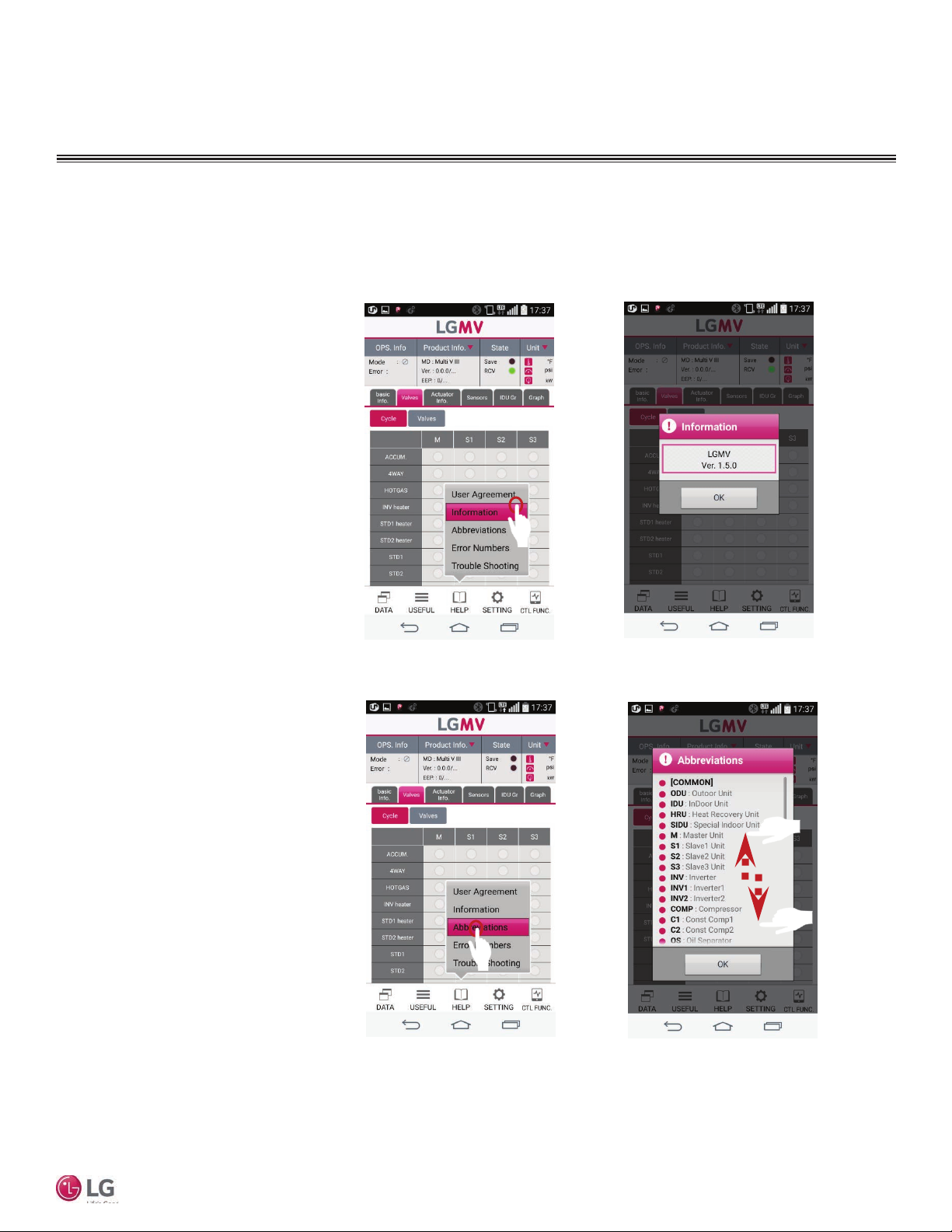
The HELP menu contains selections for Mobile LGMV information and abbreviations used on LGMV displays.
OPERATION
Help Menu
1. To display the Information window,
tap HELP. The HELP popup menu
displays (Figure 79).
2. Tap Information on the popup
menu. The Information window
displays. This window shows the
LGMV software version number
(Figure 80).
3. Tap OK when done.
4. To display the Abbreviations window, tap HELP. The HELP popup
menu displays (Figure 81).
5. Tap Abbreviations on the popup
menu. The Abbreviations window
displays. Flick up/down this list to
display all entries (Figure 82).
6. Tap OK when done.
Figure 79:
Figure 81:
Figure 80:
User Manual
Figure 82:
Due to our policy of continuous product innovation, some specifications may change without notification.
©LG Electronics U.S.A., Inc., Englewood Cliffs, NJ. All rights reserved. “LG” is a registered trademark of LG Corp.
35
Page 36
OPERATION
Help Menu
Information and Abbreviations
The HELP menu contains selections for Mobile LGMV information and abbreviations used on LGMV displays.
Figure 83: Figure 84:
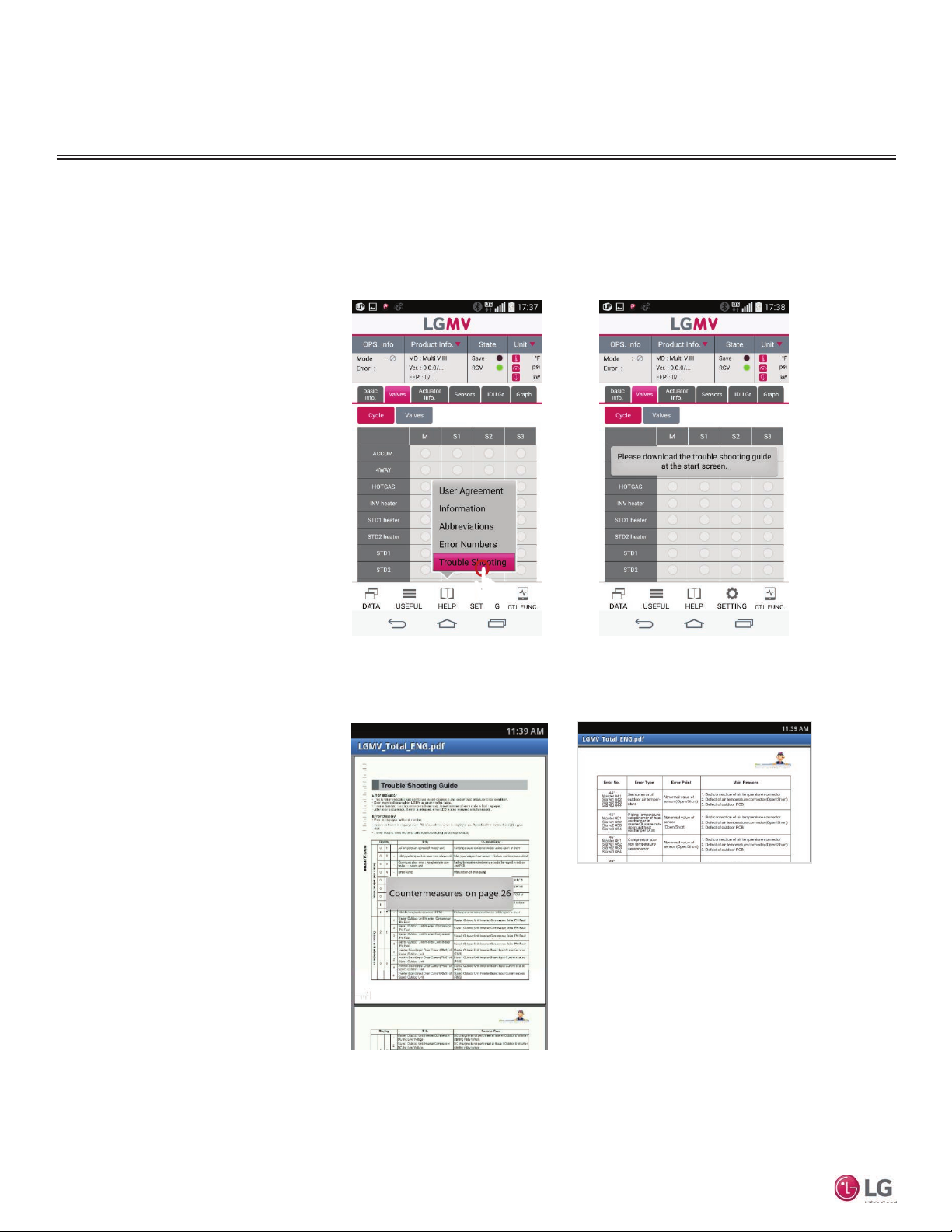
1. To display the troubleshooting
guide, tap HELP. The HELP menu
displays (Figure 83).
2. Tap Trouble Shooting. If the trou-
bleshooting guide has not yet been
downloaded, a popup message will
direct you to download the guide
(Figure 84). Refer to Downloading
the Troubleshooting Guide.
3. If the troubleshooting guide is
already downloaded, a popup message will direct you to the appropriate page of the guide (Figure 85).
4. Go to the indicated page for
information on the current error.
Read and follow the troubleshooting
information on the indicated page(s)
(Figure 86).
Mobile LGMV
Figure 85:
Figure 86:
36
Due to our policy of continuous product innovation, some specifications may change without notification.
©LG Electronics U.S.A., Inc., Englewood Cliffs, NJ. All rights reserved. “LG” is a registered trademark of LG Corp.
Page 37
OPERATION
Help Menu
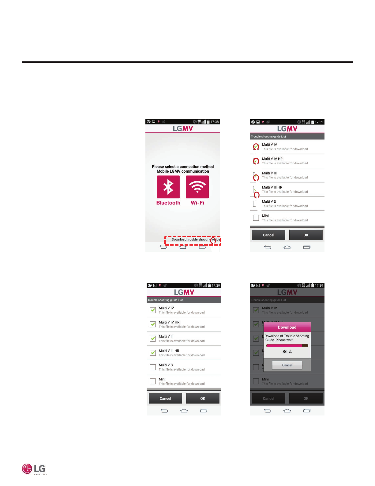
Download Troubleshooting Guide
The troubleshooting guide is not included in the app installation; it must be downloaded separately. Download the guide to the smartphone before connecting the smartphone to the Mobile LGMV wifi module.
1. Ensure the Mobile LGMV app is
installed on the smartphone.
2. Start the Mobile LGMV app. The
connection method screen is displayed (Figure 87).
3. Tap Download trouble shooting
guide at the bottom of the screen
(Figure 87). The Trouble shooting guide list screen is displayed
(Figure 88).
4. Tap the check box(es) for the
guide(s) you want to download
(Figure 88).
5. Tap the OK button (Figure 89).
The Download progress window is
displayed (Figure 90).
Figure 87:
Figure 89:
Figure 88:
User Manual
Figure 90:
Due to our policy of continuous product innovation, some specifications may change without notification.
©LG Electronics U.S.A., Inc., Englewood Cliffs, NJ. All rights reserved. “LG” is a registered trademark of LG Corp.
37
Page 38
OPERATION
Setting Menu
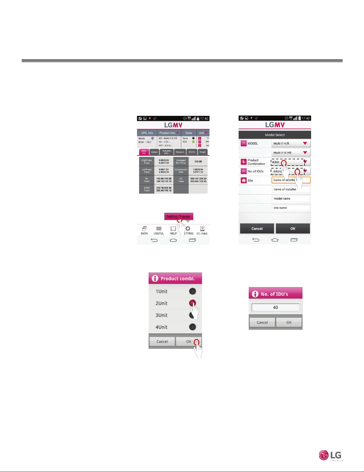
Setting Change
Setting Change allows you to define the system configuration under test (number and type of outdoor units, number of indoor units,
and site description).
1. To display Setting Change, tap
SETTING at the bottom of the
screen. The Setting Change menu
displays (Figure 91).
2. Tap Setting Change. The Model
Select screen displays
(Figure 92).
3. Tap the MODEL dropdown to select
the model type being tested
(Figure 92).
4. Tap the Product Combination
button. The Product combi. window
displays (Figure 93).
5. Tap the number (1 to 4) corresponding to the number of frames
of the outdoor unit, and then tap
OK (Figure 93).
6. Tap the No. of IDUs button
(Figure 92). The No. of IDUs win-
Mobile LGMV
dow displays (Figure 94).
7. Enter the number of indoor units in
the system being tested and then
tap OK (Figure 94).
Figure 91:
Figure 93:
Figure 92:
Figure 94:
38
Due to our policy of continuous product innovation, some specifications may change without notification.
©LG Electronics U.S.A., Inc., Englewood Cliffs, NJ. All rights reserved. “LG” is a registered trademark of LG Corp.
Page 39
Lost Wifi Communication
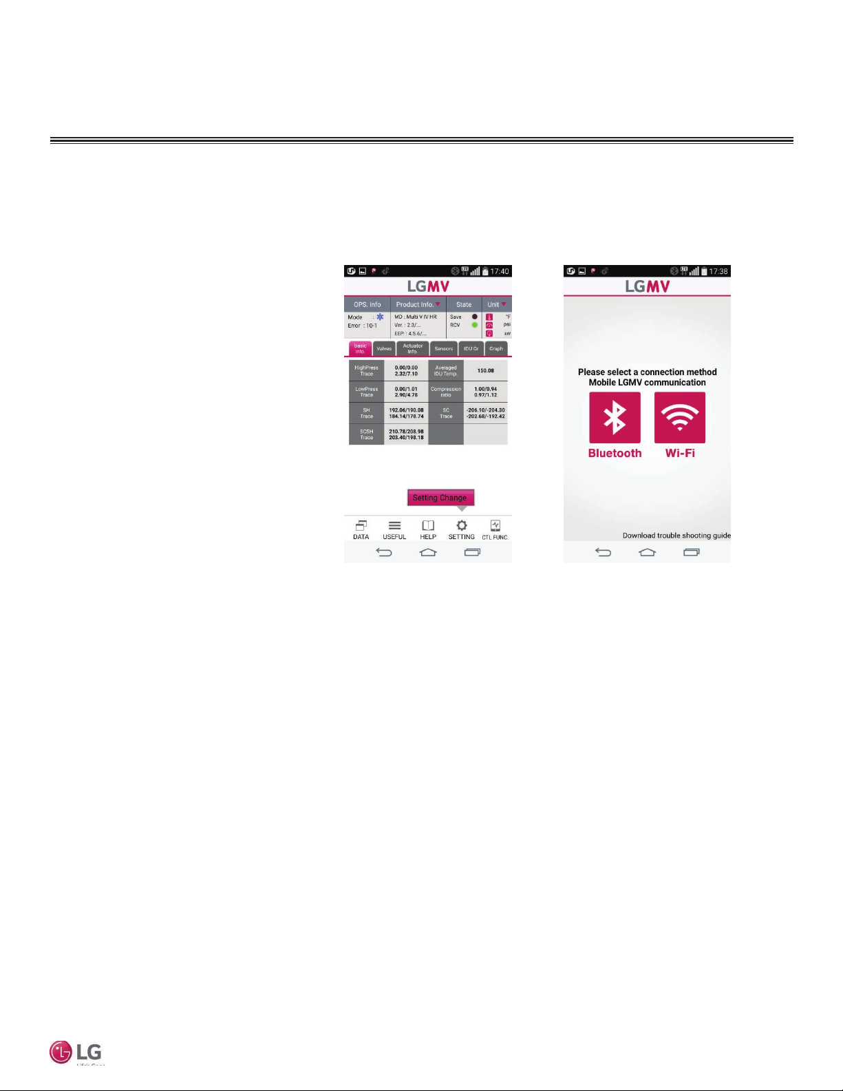
If communication between the smartphone and the wifi module is lost, you can reestablish the link.
OPERATION
Setting Menu
1. Tap SETTING at the bottom of the
screen. The Setting Change menu
is displayed (Figure 95).
2. Tap Setting Change. If wifi com-
munication has been lost, the
communication method selection
screen will display (Figure 96).
3. Tap the Wi-Fi icon on the screen
and reestablish communication with
the wifi module (Figure 96).
Figure 95:
Figure 96:
User Manual
Due to our policy of continuous product innovation, some specifications may change without notification.
©LG Electronics U.S.A., Inc., Englewood Cliffs, NJ. All rights reserved. “LG” is a registered trademark of LG Corp.
39
Page 40
OPERATION
IDU Operation
IDU Mode Control
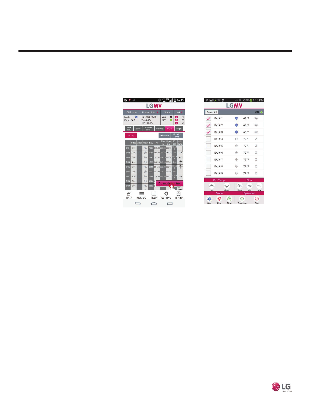
The IDU Mode Control screen allows you to turn on and off and set operating parameters for indoor units of the system being tested.
From one to a group of up to 16 IDUs can be controlled at a time.
Figure 97: Figure 98:
1. Tap the CTL FUNC button at the
bottom of the screen. The IDU
mode control menu is displayed
(Figure 97).
2. Tape IDU mode control. The
indoor unit control screen is displayed (Figure 98).
3. Refer to IDU Mode Control Screen
Description for information on this
screen’s controls.
Mobile LGMV
40
Due to our policy of continuous product innovation, some specifications may change without notification.
©LG Electronics U.S.A., Inc., Englewood Cliffs, NJ. All rights reserved. “LG” is a registered trademark of LG Corp.
Page 41
OPERATION
IDU Operation
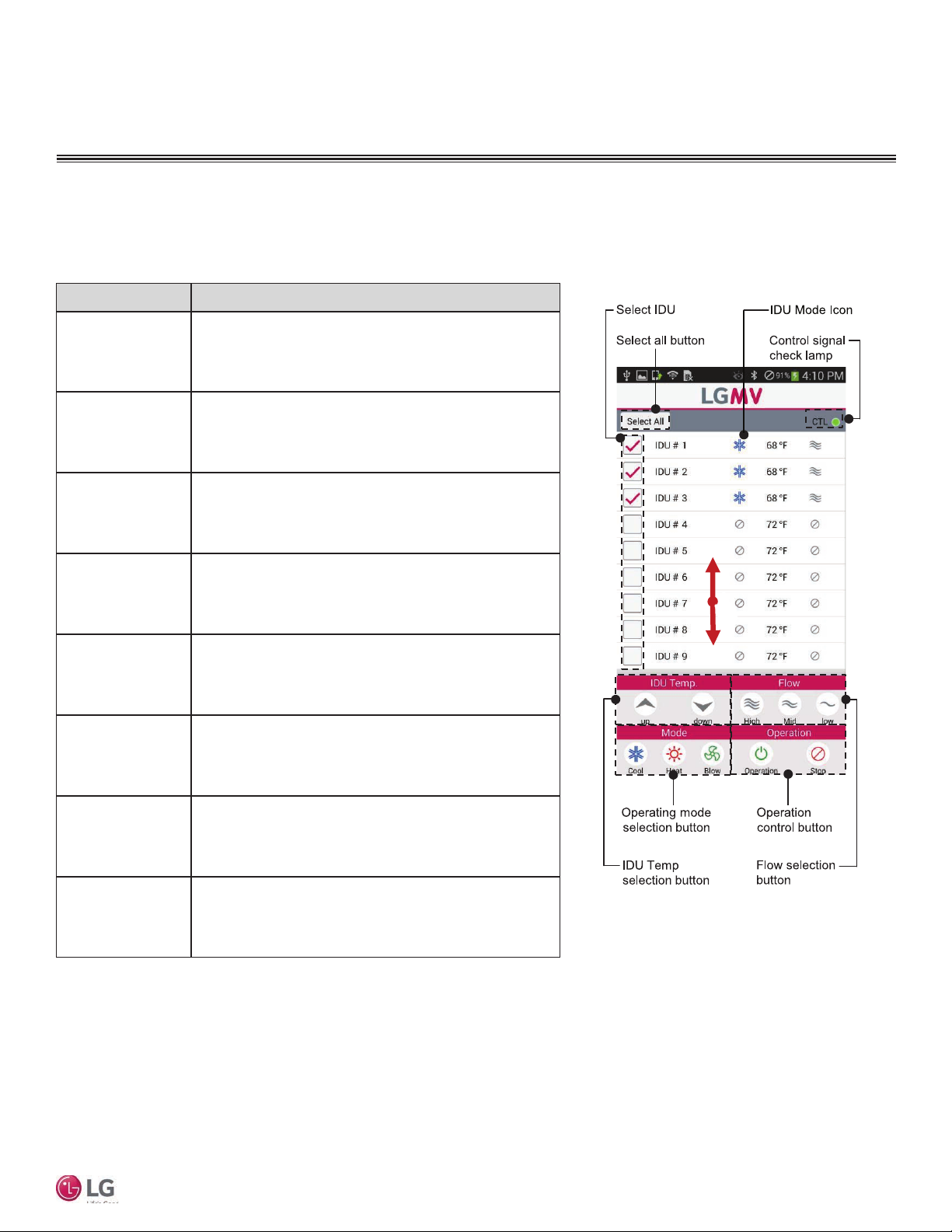
IDU Mode Control Screen Description
Refer to the table below for information on the controls and indicators of the IDU Mode Control Screen (Figure 99). Indoor units can
be controlled individually or in a group of up to 16.
Control/Indicator Description
Tap Select All to select all indoor units displayed on screen.
Select All button
Select IDU
IDU Mode Icon
Control signal
check lamp
Operation control
button
The Select All button then changes to Deselect All. Tap again to
deselect all selected indoor units.
Tap an indoor unit’s check box to select the unit. Tap a checked
box to deselect the unit.
Displays an icon to indicate the current operating mode of the
IDU: Cool, Heat, Blow (fan), or Off.
The control signal check lamp flashes three times after the
operation control button is tapped.
Press Operation to start or Stop to stop the selected indoor
unit(s).
Figure 99:
User Manual
Flow selection
button
IDU Temp selection
button
Operating mode
selection button
Press High, Mid, or Low button to select air flow for the
selected indoor unit(s).
Press the up or down arrow to raise or lower a setpoint for the
Indoor unit.
Press Cool, Heat, or Blow to set the operating mode for the
currently selected indoor unit(s).
Due to our policy of continuous product innovation, some specifications may change without notification.
©LG Electronics U.S.A., Inc., Englewood Cliffs, NJ. All rights reserved. “LG” is a registered trademark of LG Corp.
41
Page 42
OPERATION
IDU Operation
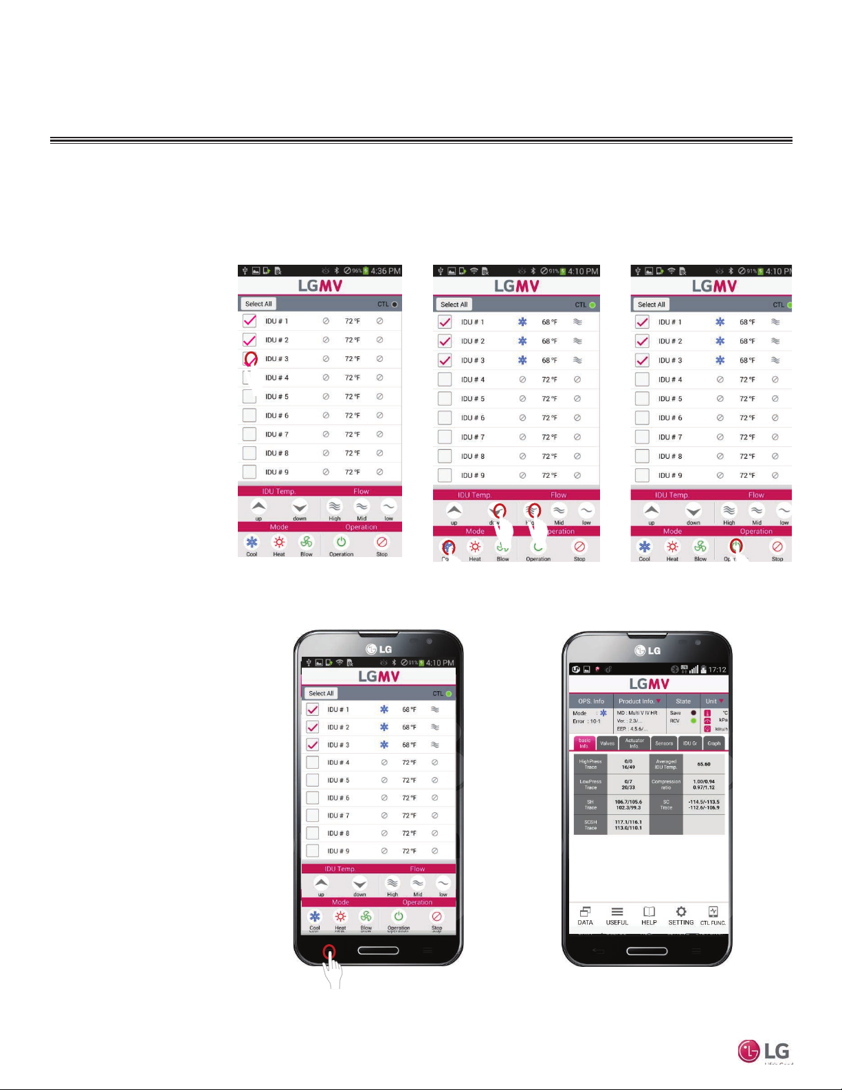
IDU Control Example
The IDU Mode Control screen allows you to turn on and off and set operating parameters for indoor units of the system being tested.
From one to a group of up to 16 IDUs can be controlled at a time.
1. Select the indoor unit(s)
(Figure 100).
2. Select the operating
mode (Figure 101).
3. Tap the Operation button to send the selected
commands to the indoor
unit(s) (Figure 102).
4. When finished with
indoor unit operation,
press the back button on
the smartphone to return
to the previous Mobile
LGMV screen (Figure
103 and Figure 104).
Mobile LGMV
Figure 100:
Figure 103:
Figure 101:
Figure 102:
Figure 104:
42
Due to our policy of continuous product innovation, some specifications may change without notification.
©LG Electronics U.S.A., Inc., Englewood Cliffs, NJ. All rights reserved. “LG” is a registered trademark of LG Corp.
Page 43
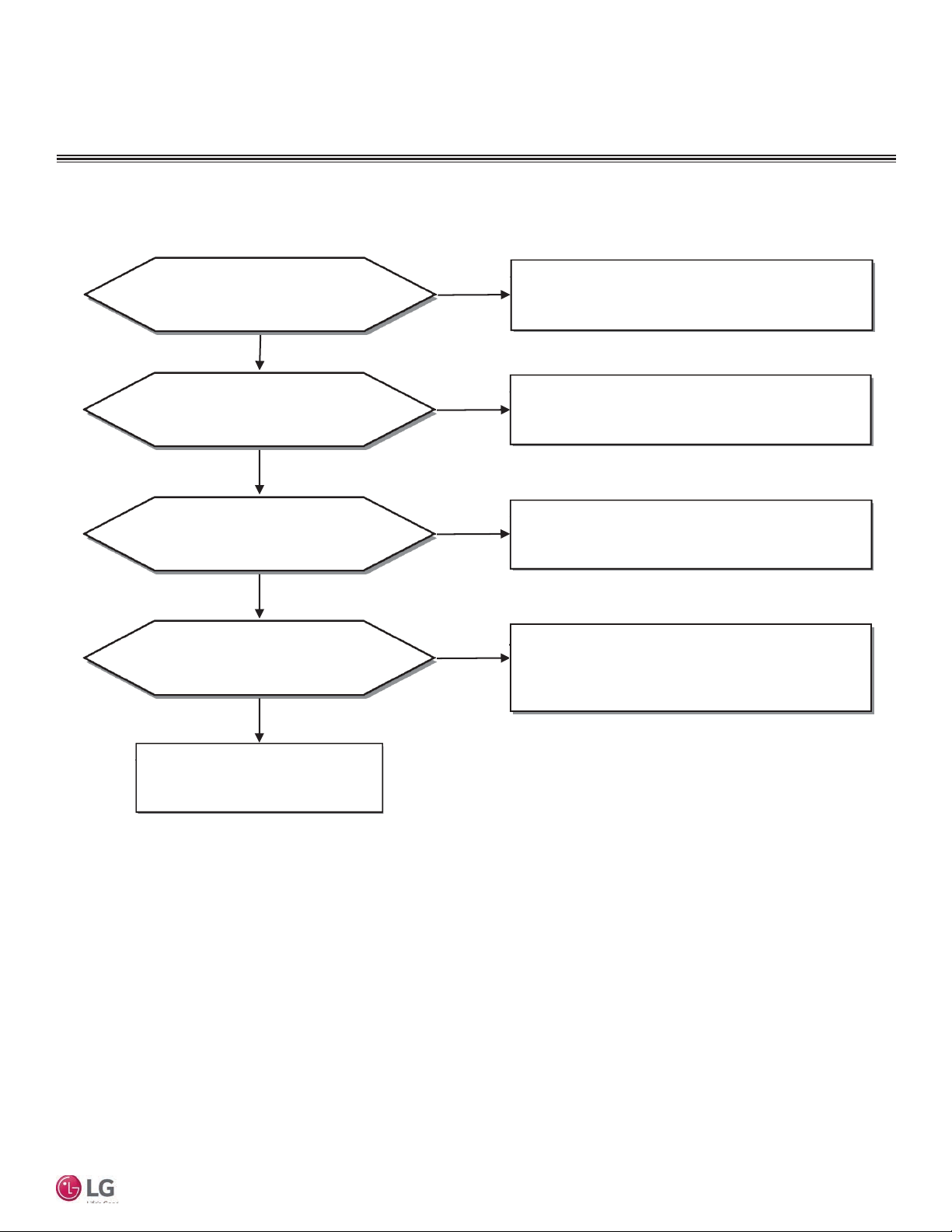
Smartphone and Wifi Module will not Connect
OPERATION
Troubleshooting
Is power connected to the outdoor unit?
Yes
Are the outdoor unit board and
Communication module connected normally?
Yes
Is another user connected?
No
Was the Communication connection
procedure accurately followed?
Yes
No
No
Yes
No
Try connecting after connecting power
to the outdoor unit
Try connecting again after outdoor unit board and
Communication module are connected normally
Try connecting after other user ends the connection
After separating the Communication module,
try connecting again.
Refer to how to set up the smart phone connection
(Communication).
User Manual
Recheck smart phone and
installation environment
Due to our policy of continuous product innovation, some specifications may change without notification.
©LG Electronics U.S.A., Inc., Englewood Cliffs, NJ. All rights reserved. “LG” is a registered trademark of LG Corp.
43
Page 44
OPERATION
Troubleshooting
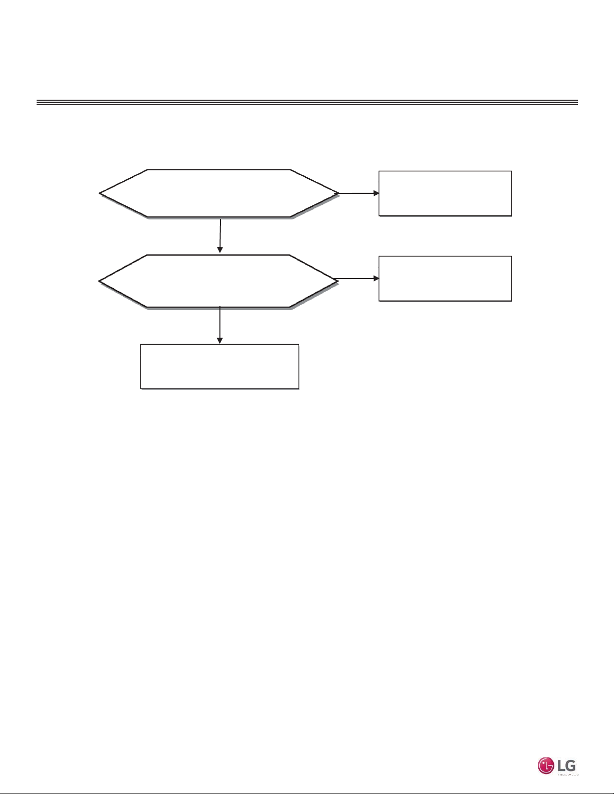
Smartphone and Wifi Module lose Connection during Operation
Mobile LGMV
Is the smart phone close enough to the wifi
module to allow connection?
Yes
Are there any obstacles (wall, shield etc.)
between the wifi module and smart phone?
Recheck smart phone and
installation environment
No
No
Yes
Move the smart phone
closer to the wifi module
Avoid (or remove) the
obstacle causing the issue
44
Due to our policy of continuous product innovation, some specifications may change without notification.
©LG Electronics U.S.A., Inc., Englewood Cliffs, NJ. All rights reserved. “LG” is a registered trademark of LG Corp.
Page 45
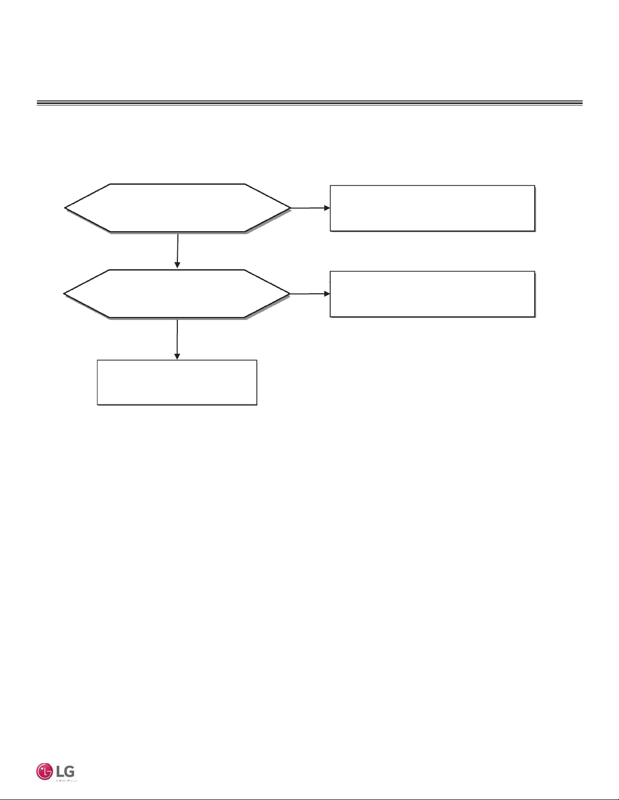
Time Gap in Saved Data
OPERATION
Troubleshooting
Does the smart phone meet
the recommended specifications?
Yes
Is another app (game, browser, etc.)
running while saving data?
No
Check app installed in smart phone
No
Yes
Use a smart phone that meets the
recommended specifications
1. Do not use any other app while saving data
2. Reboot the smart phone and retry saving data
User Manual
Due to our policy of continuous product innovation, some specifications may change without notification.
©LG Electronics U.S.A., Inc., Englewood Cliffs, NJ. All rights reserved. “LG” is a registered trademark of LG Corp.
45
Page 46
OPERATION
Troubleshooting
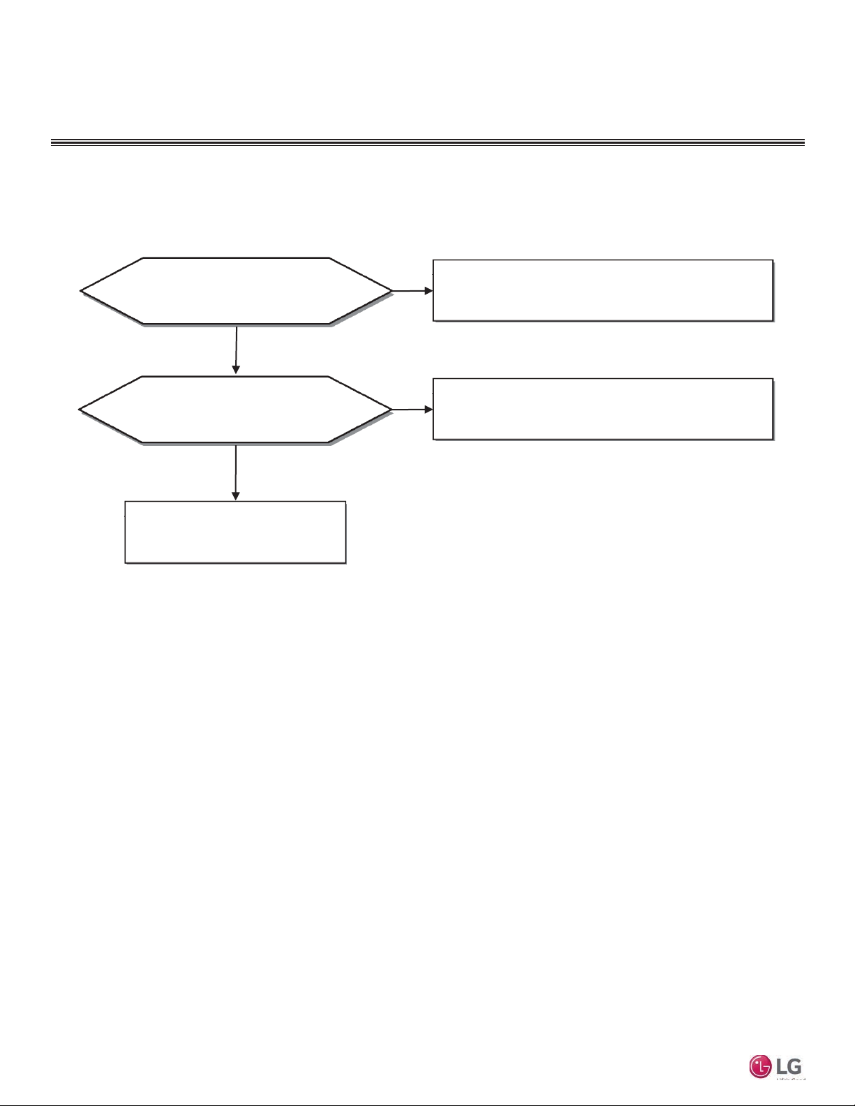
Part of Smartphone Screen not Visible or Looks Wider
Does the smart phone have a screen
Does the smart phone meet the required
Mobile LGMV
ratio correction function?
No
screen ratio specification?
Yes
Recheck smart phone and
installation environment
Yes
Run screen ratio correction function
Example: LG Optimus View smart phone:
(Settings > Display > Screen ratio correction > LGMV)
No
1. Use a smart phone with recommended specification
2. Optimized for 1280 x 720 and 800 x 480 resolution
46
Due to our policy of continuous product innovation, some specifications may change without notification.
©LG Electronics U.S.A., Inc., Englewood Cliffs, NJ. All rights reserved. “LG” is a registered trademark of LG Corp.
Page 47

User Manual
Due to our policy of continuous product innovation, some specifications may change without notification.
©LG Electronics U.S.A., Inc., Englewood Cliffs, NJ. All rights reserved. “LG” is a registered trademark of LG Corp.
47
Page 48

LG Electronics
Commercial Air Conditioning Division
11405 Old Roswell Road
Alpharetta, Georgia 30009
www.lghvac.com
LG Customer Information Center, Commercial Products
1-888-865-3026 USA
Follow the prompts for commercial A/C products and parts.
UM_MobileLGMV_Android_9_15
Supercedes UM_MobileLGMV_Android_8_15
 Loading...