

Page 1

CodePlus™ PIVD100R
Pro:Idiom® Video Distribution
Transcoder System
Installation & Setup Guide
Warranty
© Copyright 2014 LG Electronics U.S.A., Inc.
P/N: 206-4202 (Rev B)
Page 2
For Customer Support/Service, please call: 1-888-865-3026
The latest product information and documentation is available online at:
www.LGsolutions.com
WARNING
RISK OF ELECTRIC SHOCK
DO NOT OPEN
WARNIN G:
TO REDUCE THE RISK OF ELECTRIC SHOCK DO NOT REMOVE COVER (OR BACK). NO
USER-SERVICEABLE PARTS INSIDE. REFER TO QUALIFIED SERVICE PERSONNEL.
The lightning flash with arrowhead symbol, within an equilateral triangle, is intended to alert
the user to the presence of uninsulated “dangerous voltage” within the product’s enclosure
that may be of sufficient magnitude to constitute a risk of electric shock to persons.
The exclamation point within an equilateral triangle is intended to alert the user to the presence
of important operating and maintenance (servicing) instructions in the literature accompanying
the appliance.
WARNING:
TO PREVENT FIRE OR SHOCK HAZARDS, DO NOT EXPOSE THIS PRODUCT TO RAIN
OR MOISTURE.
Apparatus shall not be exposed to dripping or splashing and no objects filled with liquids, such
as vases, shall be placed on the apparatus.
L’appareil ne doit pas être exposé à des égouttements d’eau ou des éclaboussures et de plus
qu’aucun objet rempli de liquide tel que des vases ne doit être placé sur l’appareil.
REGULATORY INFORMATION:
This equipment has been tested and found to comply with the limits for a Class A digital
device, pursuant to Part 15 of the FCC Rules. These limits are designed to provide reasonable
protection against harmful interference when the equipment is operated in a commercial environment. This equipment generates, uses and can radiate radio frequency energy and, if not
installed and used in accordance with the instruction manual, may cause harmful interference
to radio communications. Operation of this equipment in a residential area is likely to cause
harmful interference in which case the user should be required to correct the interference at
his own expense.
CAUTION:
Do not attempt to modify this product in any way without written authorization from LG
Electronics U.S.A., Inc. Unauthorized modification could void the user’s authority to operate
this product.
NOTE TO SATELLITE DISH INSTALLER:
This reminder is provided to call your attention to Articles 810 and 820 of the 2002 National
Electrical Code. Refer to Article 810, in particular 810-1 and 810-15, for required grounding of
the metal dish antenna. Refer also to 810-2 which, by reference to Article 820, requires that
the satellite dish coaxial cable shield be connected to the grounding system of the building as
close to the point of cable entry as practical.
COMPLIANCE:
The responsible party for this product’s compliance is: LG Electronics U.S.A., Inc.
2000 Millbrook Drive, Lincolnshire, IL 60069, USA • Phone: 1-847-941-8000
Marketed and Distributed in the United States by LG Electronics U.S.A., Inc.
2000 Millbrook Drive, Lincolnshire, IL 60069
2
© Copyright 2014 LG Electronics U.S.A., Inc.
206-4202
Page 3

IMPORTANT SAFETY INSTRUCTIONS
1. Read these instructions.
2. Keep these instructions.
3. Heed all warnings.
4. Follow all instructions.
5. Do not use this apparatus near water.
6. Clean only with dry cloth.
7. Do not block any ventilation openings.
Install in accordance with the manufacturer's instructions.
8. Do not install near any heat sources,
such as radiators, heat registers, stoves,
or other apparatus (including amplifiers)
that produce heat.
9. Do not defeat the safety purpose of the
polarized or grounding-type plug. A polarized plug has two blades with one wider
than the other. A grounding-type plug has
two blades and a third grounding prong.
The wide blade or the third prong are
provided for your safety. If the provided
plug does not fit into your outlet, consult
an electrician for replacement of the
obsolete outlet.
10. Protect the power cord from being walked
on or pinched, particularly at plugs,
convenience receptacles, and the point
where it exits from the apparatus.
11. Only use attachments/accessories
specified by the manufacturer.
12. Use only with the cart, stand, tripod,
bracket, or table specified by the
manufacturer or sold with the apparatus.
When a cart is used, use caution when
moving the cart/apparatus combination
in order to avoid injury from tip-over.
13.
Refer all servicing to qualied service
personnel. Servicing is required when the
apparatus has been damaged in any way,
such as power-supply cord or plug is
damaged, liquid has been spilled or
objects have fallen into the apparatus, the
apparatus has been exposed to rain or
moisture, does not operate normally, or
has been dropped.
14. Power Sources
This product should be operated only from the
type of power source indicated on the marking
label. If you are not sure of the type of power
supply to your INSTALLATION, consult your
product dealer or local power company.
15. Overloading
Do not overload wall power outlets and
extension cords as this can result in a risk of
fire or electric shock.
16. Disconnect Device
The AC mains plug is used as the disconnect
device. The disconnect device must remain
readily operable.
17. Object and Liquid Entry
Never push objects of any kind into this
product through openings as they may touch
dangerous voltage points or short-out parts
that could result in a fire or electric shock.
Never spill liquid of any kind on the product.
Do not use liquid cleaners or aerosol cleaners.
18. Outdoor Use
Warning: To prevent fire or shock
hazards, do not expose this product
to rain or moisture.
19. Wet Location
Do not use this product near water or mois-
ture or in an area, such as a basement, that
might become flooded. The apparatus shall
not be exposed to dripping or splashing and
no objects filled with liquids, such as vases,
shall be placed on the apparatus.
20. Test Equipment
In some cases, LG has supplied or recommended the use of test equipment and
devices for the setup and testing of the equipment. The operation and maintenance of test
equipment is described in their associated
instruction manuals. Please refer to these
manuals for explicit instructions regarding the
safe use and handling of the equipment.
(Continued on next page)
206-4202
3
Page 4

IMPORTANT SAFETY INSTRUCTIONS
(Continued from previous page)
21. Damage Requiring Service
Unplug this product from the wall power
outlet and refer servicing to qualied service
personnel under the following conditions:
a. If the power-supply cord or plug is damaged.
b. If liquid has been spilled, or objects have
fallen into the product.
c. If the product has been exposed to rain or
water.
d.
If the product does not operate normally
by following the operating instructions.
Adjust only those controls that are covered
by the operating instructions, as an
improper adjustment of other controls may
result in damage and will often require
extensive work by a qualied technician to
restore the product to its normal operation.
e. If the product has been dropped or the
cabinet has been damaged.
f. If the product exhibits a distinct change in
performance.
Caution: Refer all servicing to qualied
service personnel.
22. Servicing
23. Replacement Parts
When replacement parts are required, be sure
Caution: These servicing instructions are for use by qualied service
personnel only. To reduce the risk
of electrical shock, do not perform any
servicing other than that described in the
operating instructions unless you are
qualied to do so.
the service technician uses replacement parts
specied by the manufacturer or that have the
same characteristics as the original parts.
Unauthorized substitutions may result in re,
electric shock, or other hazards.
24. Safety Check
Upon completion of any service or repairs to
this product, ask the service technician to
perform safety checks to determine that the
product is in proper operating condition.
PIVD100R Rack Installation
(also see pages 11 and 12)
To install the PIVD100R in a rack:
• Carefully slide the PIVD100R into a standard
19-inch equipment rack.
• When mounting in the rack, make sure to use
the appropriate hardware. ALL FOUR MOUNTING SCREWS MUST BE USED.
• This equipment is not designed to support
other devices. Do NOT stack other equipment
on the top of the PIVD100R.
• Rear cabling must be dressed and supported
so that the weight of the cabling is not a strain
on the PIVD100R connectors.
• MOUNTING OF THE EQUIPMENT IN THE
RACK SHOULD BE SUCH THAT A HAZARDOUS CONDITION IS NOT ACHIEVED DUE TO
UNEVEN MECHANICAL LOADING.
Rack-mount Considerations
A. Elevated Operating Ambient
If installed in a closed or multi-unit rack
assembly, the operating ambient temperature of the rack environment may be greater
than room ambient. Therefore, consideration
should be given to installing the equipment in
an environment compatible with the maximum
ambient temperature (Tma) specified by the
manufacturer (see Specifications information
in this document).
(Continued on next page)
4
206-4202
Page 5

IMPORTANT SAFETY INSTRUCTIONS
(Continued from previous page)
B. Reduced Air Flow
Installation of the equipment in a rack should
be such that the amount of air flow required
for safe operation of the equipment is not
compromised. To ventilate the system normally and avoid overheating, leave at least
1 inch (2.5 cm) on each side (including top
and bottom) of the PIVD100R. Do NOT stack
other equipment on the top of the PIVD100R.
Also, ensure that the unit’s AC power adapter
is never stacked or bundled with other AC
power adapters. Each adapter should have
adequate ventilation and should be isolated
from other heat sources.
C. Circuit Overloading
Consideration should be given to the
connection of the equipment to the supply
circuit and the effect that overloading of the
circuits might have on overcurrent protection
and supply wiring.
D. Reliable Earthing
Maintain reliable earthing of rack-mounted
equipment. Particular attention should be
given to supply connections other than direct
connections to the branch circuit (e.g. use of
power strips).
E. Mains Outlet Earthing
The apparatus with Class I construction must
be connected to a mains socket outlet with a
protective earthing connection.
PIVD100R Server Installation on a Flat Surface
To install the
top, shelf, etc.):
• Install the equipment in an environment
compatible with the maximum operating
ambient temperature (Tma) specied by the
manufacturer (see Specications information
in this document).
• Place spacers or rubber feet (not provided) on
the bottom of the
• Carefully place the
surface.
• To ventilate the system normally and avoid
overheating, leave at least 1 inch (2.5 cm) on
each side (including top and bottom) of the
PIVD100R. Do NOT stack other equipment on
the top of the PIVD100R.
PIVD100R
PIVD100R
PIVD100R
on a level surface (table
.
on the level
206-4202
5
Page 6

Table of Contents
Safety Warnings . . . . . . . . . . . . . . . . . . . . . . . 2
Important Safety Instructions. . . . . . . . . . . . 3 – 5
Table of Contents . . . . . . . . . . . . . . . . . . . . . . 6
PIVD100R Product Description . . . . . . . . . . . . 7
Setup Information . . . . . . . . . . . . . . . . . . . . 8 – 9
Rear and Front Panel Overviews . . . . . . . . . 10
Rack Installation . . . . . . . . . . . . . . . . . . . 11 – 12
Typical Rack Installation . . . . . . . . . . . . . . 11
Rack-mount Considerations . . . . . . . . . . . . 12
System Setup . . . . . . . . . . . . . . . . . . . . . 13 – 19
Typical Setup Flowchart for PIVD100R
with RF Output . . . . . . . . . . . . . . . . . . . . . . 13
Typical Setup Flowchart for PIVD100R
with IP Output . . . . . . . . . . . . . . . . . . . . . . . 14
Typical System Installation . . . . . . . . . . . . . 15
Network and Communication Setup . . . . . . . 20
Configuration Options via GUI . . . . . . . . 21 – 36
Access the PIVD100R Web GUI . . . . . . . . 21
PIVD100R System Status . . . . . . . . . . . . . 22
STB Information . . . . . . . . . . . . . . . . . . . . . 23
STB Menu Options . . . . . . . . . . . . . . . . . . . 24
PIVD100R System Setup Options . . . . . . . 27
MUX Setup Options . . . . . . . . . . . . . . . . . . 32
PIVD100R Maintenance Options . . . . . . . 34
Configuration Options via Command
Line . . . . . . . . . . . . . . . . . . . . . . . . . . . . . 37 – 60
Log In to the PIVD100R and Access
the Main Menu . . . . . . . . . . . . . . . . . . . . . . 37
View System Information . . . . . . . . . . . . . . 38
Monitor the System . . . . . . . . . . . . . . . . . . 38
STB Menu Commands . . . . . . . . . . . . . . . . 40
Setup Menu Commands . . . . . . . . . . . . . . 45
Update Menu Commands . . . . . . . . . . . . . 56
Pro:Idiom Menu Commands . . . . . . . . . . . 58
Reset the System . . . . . . . . . . . . . . . . . . . . 60
Exit the Current Session . . . . . . . . . . . . . . 60
Troubleshooting . . . . . . . . . . . . . . . . . . . . 61 – 65
PIVD100R Setup . . . . . . . . . . . . . . . . . . . . 61
PIVD100R Communication . . . . . . . . . . . . 62
Receiver Reception . . . . . . . . . . . . . . . . . . 63
Specifications . . . . . . . . . . . . . . . . . . . . . . . . 66
Document Revision History / Notes . . . . . . . 67
Open Source Software Notice . . . . . . . . . . . . 68
Warranty . . . . . . . . . . . . . . . . . . . . . Back Cover
6
206-4202
Page 7

PIVD100R Product Description
The LG CodePlus™ PIVD100R Pro:Idiom ® Video Distribution Transcoder System provides a
flexible 8- to 16-program HDTV solution for system providers who provide satellite delivered
content to commercial facilities (hotels, hospitals, etc.). The PIVD100R incorporates eight
100BaseTX Ethernet interface X-Ports that connect up to eight satellite set-top boxes (STBs)
from either DIRECTV ® or DISH Network ® satellite service.
Features
• Two output options: RF or IP (concurrent operation not supported)
− RF output: The PIVD100R generates four contiguous 256-QAM cable channels, with
up to two DIRECTV or three DISH Network program streams multiplexed on each
channel. This capability provides up to 8 HD programs of DIRECTV content or up to
12 HD programs of DISH Network content.
− IP output: The PIVD100R provides up to 8 HD programs of DIRECTV content or up
to 16 HD programs of DISH Network content.
• Transcodes satellite content for distribution
• Built-in Pro:Idiom content protection
• Supports Pro:Idiom encryption key maintenance
• Transcoded output supports Closed Captions and V-Chip (Parental Control)
(if included in the signal source)
• Remote management capability over Ethernet via either graphical user interface (GUI) or
command line interface
• Unit does not require local monitor, keyboard, or mouse connection
• Small, lightweight chassis
• 19-inch rack-mountable
• 1U height prole to minimize rack space usage
The PIVD100R converts satellite MPEG-4 HD programming to an encrypted, encoded
transport stream. A Pro:Idiom-compatible television is required to view premium HD content,
and a proper session ID must be set at the TV in order for Pro:Idiom decryption to be enabled.
LG’s Pay-Per-View (PPV) partners can set up this session through their interface. LG’s FreeTo-Guest (FTG) Mode of operation also enables Pro:Idiom decryption.
Multiple PIVD100R units may be combined in the head end to deliver an entire channel
lineup of HD programming.
Note: Design and specifications subject to change without prior notice.
206-4202
7
Page 8

Setup Information
This document provides installation and setup support only for the PIVD100R. The satellite
dish antenna and satellite STBs must be installed and operating before you proceed to set up
the PIVD100R. LG recommends that the system be professionally installed.
Check the following items before you begin the PIVD100R installation and setup procedures.
Satellite Dish Antenna
__ The satellite dish must be located where it will have unobstructed access to the satellite
signals. At least RG-6 or larger coaxial cables must be installed between the satellite dish
antenna system and the satellite STB. Refer to documentation provided with the satellite
dish antenna.
__ Ensure the appropriate satellite dish configuration (either 3-LNB or 5-LNB depending on
the satellite provider) is in place for MPEG-4 HD channel reception. If the number of
transcoders exceeds the dish antenna capacity, multi-switch equipment will be required.
For more information, refer to the manufacturer’s documentation.
Satellite STBs
__ DIRECTV satellite service: Up to eight COM 23 satellite STBs are supported for either RF
or IP output.
__ DISH Network satellite service: Up to six ViP ® 222 or ViP 222k satellite STBs are
supported for RF output, or up to eight ViP 222 or ViP 222k satellite STBs are supported
for IP output.
__ Refer to the manufacturer’s documentation, and carefully follow the system setup
procedures for each satellite STB. (The satellite STBs provide the X-Port signal inputs
for the PIVD100R.)
__ Authorization from the satellite service provider is required for HD channels. Contact the
provider to get subscription programming authorization for each satellite STB.
PIVD100R
__ Unpack the PIVD100R unit and all accessories.
PIVD100R Accessories: • AC Power Cord and Adapter
• 8 x 1 meter CAT5E Cables (for X-Port connections)
__ Select the location for mounting the PIVD100R. Ensure that adequate ventilation is
available
__ Obtain the necessary attachment hardware to mount the PIVD100R chassis in its targeted
location.
__ Plan and install the necessary cabling and network (Ethernet) and AC power access for
the PIVD100R. You will also need the following to connect a PC directly to the PIVD100R
for system setup purposes: FTDI TTL-USB cable (P/N TTL-232R-5V-AJ).
8
.
206-4202
Page 9

Setup Information (Cont.)
Channel Assignments for RF Output
__ Create a channel assignment plan for the installation site, or modify an existing plan to
incorporate the RF output of the PIVD100R. Ensure that up to four contiguous CATV
channels are allocated for the PIVD100R RF output. The PIVD100R uses a 256-QAM
modulation format, thereby occupying approximately 24 MHz of frequency spectrum.
The RF start channel is user-assigned during system setup, and the remaining channels
are then automatically assigned per EIA-542 STD CATV frequency allocation standards.
For example, if the RF start channel assignment is channel “2,” the three remaining
channels will be “3” “4” and “5”. However, if the RF start channel assignment is “6,” the
three remaining channels will be “95” “96” and “97”. Refer to EIA-542 STD CATV frequency
allocation tables for further information as required.
The highest available RF channel number for the PIVD100R is “135.” Thus, to allocate
all four channels available for PIVD100R RF output, the RF start channel must be set no
higher than “132.”
__ Find a location on the frequency spectrum that is free of existing noise.
Channel Assignments for IP Output
__ The PIVD100R outputs IPv4 multicast streams. Ensure the institution’s IP network and
room receivers support IPv4 multicast and that the network is capable of selectively routing
multicast traffic. Refer to vendor equipment documentation for further information.
__ Create a channel assignment plan for the installation site, or modify an existing plan to
incorporate the IP output of the PIVD100R. Ensure that up to 16 unused and unreserved
IPv4 multicast addresses, within the designated range 224.0.0.0 to 239.255.255.255, are
allocated for the PIVD100R IP output.
IP channels are user-assigned during system setup. You may opt to specify an IP start
channel and enable the system to auto-increment the remaining channel assignments. For
example, if the IP start channel assignment is “227.0.0.40,” the remaining channels will be
“227.0.0.41,” “227.0.0.42,” etc. Or, you may opt to manually specify the IP details for each
IP channel.
__ Reserve at least one User Datagram Protocol (UDP) port for the multicast data streams.
You can use the system default (1234) or another unassigned port number for each data
stream, as required, for example, 50000, 50001, etc. The port(s) must avoid conict with
other protocols in use.
Note: Refer to the IANA IPv4 Multicast Address Space Registry and/or the IANA Service
Name and Transport Protocol Port Number Registry for further IP address/port information as
required.
206-4202
9
Page 10
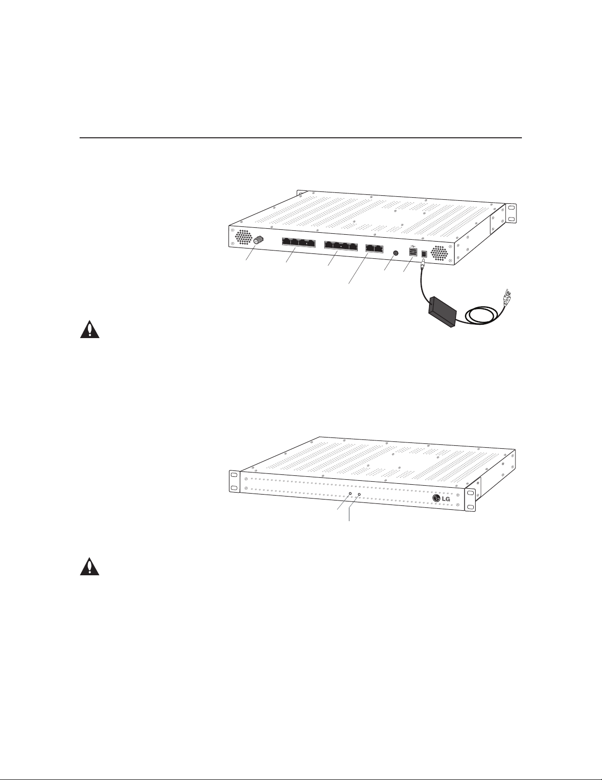
Rear and Front Panel Overviews
PIVD100R Rear View
Disconnect Device
The AC mains plug is used as the
disconnect device. The disconnect
device must remain readily operable.
PIVD100R Front View
RF OUT
RF-OUT
8 7 6 5
X-Ports
8, 7, 6, 5
X-Port
POWER LED
X-Port
4 3 2 1
X-Ports
4, 3, 2, 1
Feature & Control
(Ethernet) Ports
STATUS LED
Feature Port Control Port
Service Port
Service
Port
PWR
STATUS
POWER
12V
USB
Ports
AC Power
Cord & Adapter
Ventilation Holes
Air flow must not be obstructed. To ventilate
the system normally and avoid overheating,
leave at least 1 inch (2.5 cm) on each side
(including top and bottom) of the PIVD100R.
Do NOT stack other equipment on the top of
the PIVD100R.
10
206-4202
Page 11
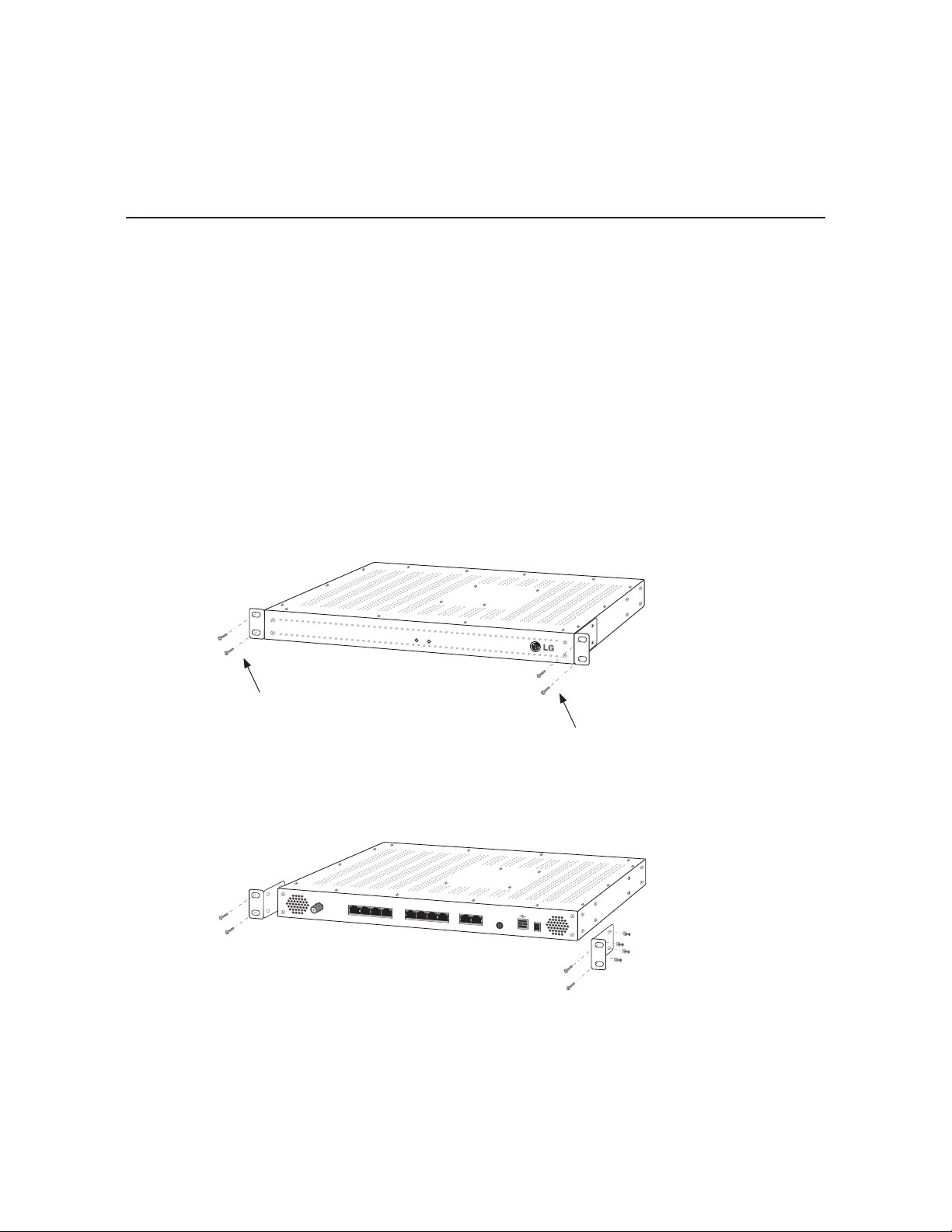
Rack Installation
STATUS
PWR
Typical Rack Installation
1. (Optional) As shipped, the PIVD100R mounting brackets are attached ush with the front of
the unit (see diagram a). If desired, the mounting brackets may be detached from the unit
and reattached, for example, so that they are ush with the rear of the unit (see diagram b).
If you wish to change the location/orientation of the mounting brackets, carefully remove
each of the four (M4 x 10 mm) screws and attendant washers (one at and one lock washer
per screw) holding each bracket in place. Then, use the same screws and washers to
reattach the mounting brackets in the desired location.
2. Carefully slide the chassis into a standard 19-inch equipment rack.
3. Use all four mounting screws to secure the chassis to the rack.
(a)
(b)
PWR
STATUS
To rack
To rack
RF-OUT
X-Port
8 7 6 5
X-Port
4 3 2 1
Feature Port Control Port
POWER
Service Port
12V
Use at washer and
lock washer with each
M4 x 10 mounting
bracket screw.
206-4202
11
Page 12
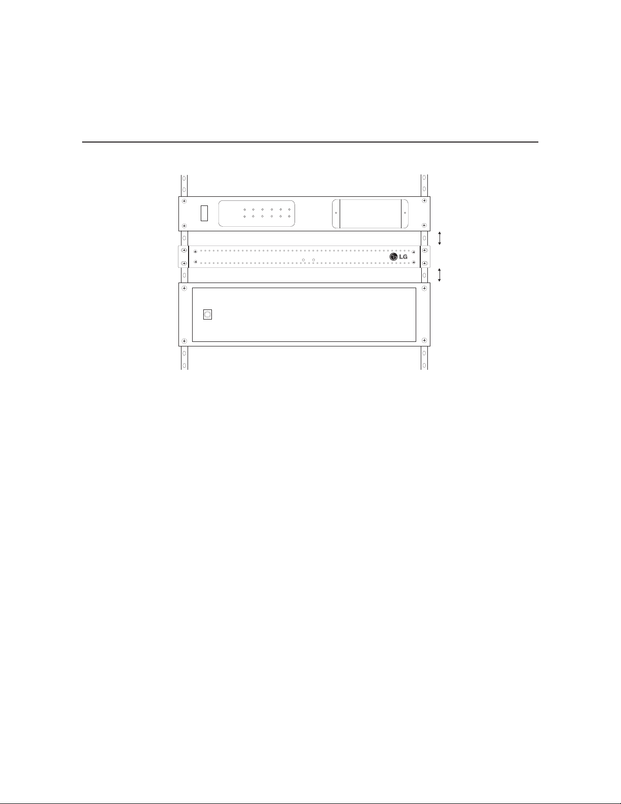
Rack Installation (Cont.)
Front View
of Rack Cabinet
PWR STATUS
PWR STATUS
1 inch minimum
1 inch minimum
Rack-mount Considerations
A. Elevated Operating Ambient
If installed in a closed or multi-unit rack assembly, the operating ambient temperature of the rack
environment may be greater than room ambient. Therefore, consideration should be given to
installing the equipment in an environment compatible with the maximum ambient temperature
(Tma) specified by the manufacturer (see Specifications information in this document).
B. Reduced Air Flow
Installation of the equipment in a rack should be such that the amount of air flow required for
safe operation of the equipment is not compromised. To ventilate the system normally and
avoid overheating, leave at least 1 inch (2.5 cm) on each side (including top and bottom) of
the PIVD100R. Do NOT stack other equipment on the top of the PIVD100R. Also, ensure that
the unit’s AC power adapter is never stacked or bundled with other AC power adapters. Each
adapter should have adequate ventilation and should be isolated from other heat sources.
C. Circuit Overloading
Consideration should be given to the connection of the equipment to the supply circuit and the
effect that overloading of the circuits might have on overcurrent protection and supply wiring.
D. Reliable Earthing
Maintain reliable earthing of rack-mounted equipment. Particular attention should be given to
supply connections other than direct connections to the branch circuit (e.g. use of power strips).
E. Mains Outlet Earthing
The apparatus with Class I construction must be connected to a mains socket outlet with a
protective earthing connection.
12
206-4202
Page 13
CAT5E
Cable
Feature Port
PIVD100R
IP
Distribution
Network
Network
Room
Receiver
Room
Receiver
Room
Receiver
Laptop
PC
Service Port
Connection
Ethernet
Satellite
STB
X-Port n **
Satellite Signal/
Distribution
*
Satellite In
X-Port 3
X-Port 2
X-Port 1
.
.
.
1000BaseT
Full Duplex
System Setup
Refer to the following diagrams, and complete the system installation as described on pages
15 to 19.
Caution: Do NOT make system connections until instructed to do so during the
system installation procedure. In some instances, configuration steps must be
performed before physical connections are made.
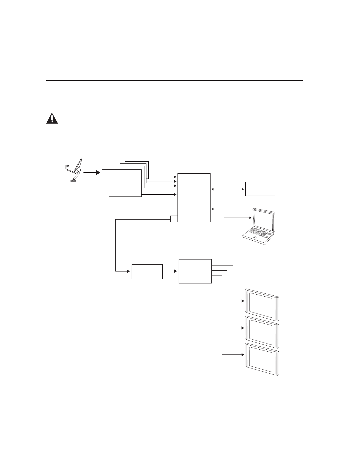
Typical Setup Flow Chart for PIVD100R with RF Output
Satellite Signal/
Distribution
Satellite In
Satellite
STB
*
Ethernet
X-Port 1
X-Port 2
X-Port 3
X-Port n **
.
.
.
PIVD100R
Network
RF
Cable
Combiner
* Multi-switch will be necessary if the number
of transcoders exceeds the dish antenna’s
capacity.
** Where n is the last X-Port used. Up to eight
COM 23 or six ViP 222/ViP 222k STBs are
supported for RF output.
RF Out
RF
Distribution
System
Service Port
Connection
Laptop
PC
Room
Receiver
Room
Receiver
Room
Receiver
206-4202
13
Page 14
System Setup (Cont.)
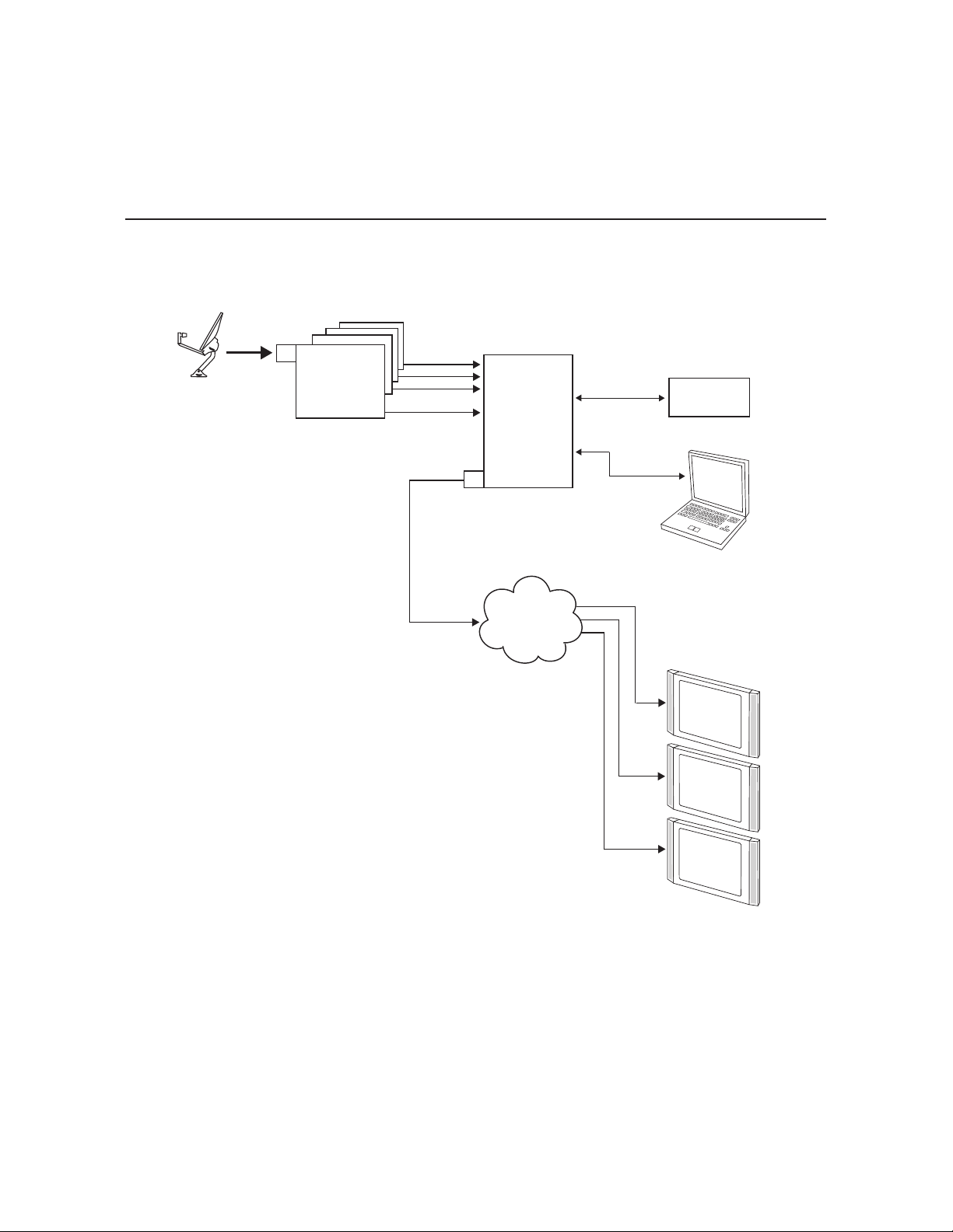
Typical Setup Flow Chart for PIVD100R with IP Output
Satellite In
Satellite
Satellite Signal/
Distribution
*
STB
Ethernet
1000BaseT
Full Duplex
* Multi-switch will be necessary if the number
of transcoders exceeds the dish antenna’s
capacity.
** Where n is the last X-Port used. Up to
eight COM 23 or ViP 222/ViP 222k STBs are
supported for IP output.
CAT5E
Cable
X-Port 1
X-Port 2
X-Port 3
.
.
.
X-Port n **
PIVD100R
Feature Port
IP
Distribution
Network
Service Port
Connection
Network
Laptop
PC
Room
Receiver
Room
Receiver
14
Room
Receiver
206-4202
Page 15

System Setup (Cont.)
Typical System Installation
(see also Typical Setup Flow Charts on the previous pages)
1. Verify that each satellite STB is set up and functioning. Each STB should be powered up,
initialized, authorized, and displaying the default channel properly—refer to the manufacturer’s
documentation.
Caution: Do NOT make any connections between the satellite STBs and the
PIVD100R until you have verified that the STBs are authorized and functioning
properly.
2. For each satellite STB: Connect one of the supplied CAT5E cables between one of the
X-Ports on the PIVD100R rear panel and the ETHERNET port on the satellite STB.
Note: Once you make the connection between a satellite STB and the PIVD100R, STB
front panel and remote control functionality may be limited. If necessary, to restore IR
remote usability, unplug the X-Port cable and reset the STB. (The STB/tuner channels will
be set later during the system setup.)
3. To enable remote management, connect one end of a CAT5 RJ-45 Ethernet cable to the
Control Port on the PIVD100R rear panel, and connect the other end of the cable to the
institution’s network.
Caution: The subnet 192.168.0.x is reserved for STB communication and
cannot be used for the Control Port network subnet. This is the only restriction;
for example, you can use 192.168.1.x, 10.x.x.x, etc. Contact your service
representative for further information.
4. Connect the PIVD100R power supply to the POWER connector on the PIVD100R rear panel.
Then, plug the AC power cord into a powered AC line receptacle. When power is applied, the
PWR (Power) LED on the PIVD100R front panel will initially flash red and then turn green.
The boot-up process for the PIVD100R may take up to 90 seconds. When boot-up is
complete, the STATUS LED on the PIVD100R front panel will light continuously green.
5. Once the STATUS LED is lit continuously, use the FTDI TTL-232R-5V-AJ cable to connect
a PC to the Service Port on the PIVD100R rear panel.
6. Using HyperTerminal or an equivalent terminal emulation program on the PC, congure the
serial port as follows: Bits per second/baud = 115200; Data bits = 8; Parity = None; Stop
bits = 1; Flow Control = None.
Once the connection is established, you should see a login prompt. (If the login prompt is
not automatically displayed, press Enter to refresh the screen.)
7. At the
login as:
type Password4Partners (case-sensitive) and press Enter.
Note: After the system setup is complete, it is highly recommended that you
change the admin user password from its default value. See “Change the Login
Password” on page 56 for further information.
prompt, type admin and press Enter. Then, at the
password:
prompt,
206-4202
(Continued on next page)
15
Page 16

System Setup (Cont.)
(Continued from previous page)
8. At the
Command >
PIVD100R command prompt to view current menu, if desired.)
The initial System Information display identifies PIVD100R default configuration settings,
including the Control Port IP address, the STB type, and the output conguration, for
example:
prompt, type info and press Enter. (You can press Enter at any
PIVD100R
Pro:Idiom Video Distribution Transcoder System
Copyright (c) 2010-2012 LG Electronics U.S.A., Inc.
Copyright (c) 2010-2012 Zenith Electronics LLC
SN: 101-12470001
Version 1.5
HW id: 3-207-79-4
Ctrl MAC: 00:0C:63:3B:00:BE
Ctrl IP: 136.166.60.92
STB Type: DirecTV
Output: RF
RF config: Mode 2, QAM-B, RF: 6 MHz, 5.36 MSps
RF channels: 3 4 5 6
Local time: Thu Mar 22 14:42:02 CDT 2012
9. Check the Ctrl IP (Control Port IP address) eld in the System Information display. By
default, the PIVD100R uses DHCP; thus, the DHCP server, if congured, assigns an IP
address to the PIVD100R once the PIVD100R successfully connects to the network.
• If the Ctrl IP eld shows an IP address, the PIVD100R is up and running on the network.
Continue with step 10.
• If the network is congured for DHCP but the Ctrl IP eld is blank, refer to “Network Setup”
troubleshooting information on page 61.
• If the network is not congured for DHCP, you will need to congure a static IP address
for the PIVD100R. Complete steps 10 to 13 (as required), and then set the PIVD100R IP
address using the commands indicated in step 14.
10. Check the Output eld in the System Information display. If the default value (RF) does not
identify the appropriate output type, set the output mode as follows:
a) At the
b) Use the Setup Menu “omode” command, as described on page 47, to set the appropriate
11. The next step depends on the output mode:
• If you are setting up the system for RF output, continue with step 12.
• If you are setting up the system for IP output, go to step 13.
Command >
output mode.
prompt, type setup and press Enter to access the Setup Menu.
16
(Continued on next page)
206-4202
Page 17

System Setup (Cont.)
(Continued from previous page)
12. (RF output only) Complete PIVD100R RF output configuration as follows:
a) If the
b) Use the Setup Menu “rf” command, as described on page 50, to congure the RF mode
c) Connect RF OUT on the PIVD100R rear panel to the RF distribution center combiner,
d) Go to step 14.
13. (IP output only) Complete PIVD100R IP output configuration as follows:
a) If the
b) At the
c) The IP Output Conguration Menu offers two options for configuring output IP channels:
d) Once you have completed the output IP channel conguration, at the next
e) Connect a CAT5E or better cable between the Feature Port on the PIVD100R rear
f) Continue with step 14.
Command >
Setup Menu.
and the RF channels.
Note: By default, the PIVD100R is configured for QAM-B RF output; thus, when you are
prompted to select the RF mode (initial prompt before RF channel configuration), the
default value shown in square brackets should show the appropriate option for RF output.
and balance the RF signal so that the signal level at the TV(s) is between 0 to +7 dBmV.
Caution: For proper system performance, the PIVD100R signal level at the
TV input (ANTENNA IN) must be between 0 to +7 dBmV. Note that additional
equipment (i.e., attenuators) may be required to adjust the signal level.
Command >
Setup Menu.
Setup Command >
Output Conguration Menu.
• To manually congure the output IP channels, use the “set’’ command. You will need
to specify a multicast IP address and the multicast port number for each STB/tuner.
• To auto-congure output IP channels from a base multicast IP address and port
number, use the “ll” command. Once you enter the base multicast IP address and
the multicast port number, the system will auto-increment the remaining IP channels.
Refer to “Congure the IP Output” on pages 50 to 53 for further information on the IP
Output Conguration Menu commands. Make sure to use the IP Output Conguration
Menu “apply” command to conrm and apply the conguration data to the system.
prompt is on display, type setup and press Enter to access the
prompt is on display, type setup and press Enter to access the
prompt, type ipout and press Enter to access the IP
IP
Output Command >
prompt.
panel and the institution’s IP distribution network.
prompt, type exit and press Enter to return to the Setup Menu
206-4202
(Continued on next page)
17
Page 18

System Setup (Cont.)
(Continued from previous page)
14. (Optional) For remote management purposes, you can set a static IP address for the
PIVD100R Control Port as follows:
a) If the
b) At the
c) Use the Network Configuration Menu “ip” and “dns” commands to configure the Control
Note: Review the New Network Configuration overview carefully before you confirm the
Control Port configuration settings. Ensure each of the addresses was entered correctly.
Note: If you change the Control Port configuration, you will be prompted to reset the
system. If you intend to modify additional configuration settings during the current session,
you may wait until all changes are complete before you reset the system.
15. Once all physical connections to the PIVD100R have been made and the Control Port IP
address has been assigned or configured, you also have the option to complete the
system setup remotely using either the web GUI or the command line interface.
• To complete the system setup in the current session (via the Service Port), continue with
• If you wish to complete the setup remotely, reset the system at this time: At either the
16. Check the STB Type field in the System Information display (if necessary, you can rerun
the “info” command from either the
default value (DIRECTV) does not identify the appropriate service provider, set the STB
type as follows:
a) If the
b) Use the Setup Menu “type” command, as described on page 47, to select the STB type.
Note: If you set a new STB type, you will be prompted to reset the system. If you intend to
modify additional configuration settings during the current session, you may wait until all
changes are complete before you reset the system.
Command >
Setup Menu.
Setup Command >
display the current network configuration, followed by the Network Configuration Menu.
Port. Refer to “Configure the Control Port” on pages 48 to 49 for further information.
step 16.
prompt is on display, type setup and press Enter to access the
prompt, type setip and press Enter. The system will
Command >
When you are ready, establish remote communication with the PIVD100R, and then
continue with step 16. Note that you may use the GUI to perform the conguration steps,
if desired. Refer to “Network and Communication Setup” on page 20 for information on
establishing remote communication with the PIVD100R and/or “Conguration Options
via GUI” on pages 21 to 36 for further information on the GUI.
Setup Menu.
prompt or the
Command >
Setup Command >
Command > or Setup Command >
prompt is on display, type setup and press Enter to access the
prompt, type reset and press Enter.
prompt). If the
18
(Continued on next page)
206-4202
Page 19

(Continued from previous page)
System Setup (Cont.)
17. If the
18. Set the channel(s) on each of the installed STBs as follows:
Setup Command >
Command >
a) At the
b) At the
connected to the STB for which you wish to set the channel(s). Then, press Enter.
The system will identify the current STB and then display an STB command prompt,
for example:
prompt.
Command >
Enter STB number >
prompt is on display, type exit and press Enter to return to the
prompt, type stb and press Enter to access the STB Menu.
prompt, type the number of the PIVD100R X-Port
Current STB: STB-1
STB-1 Command >
c) Use the STB Menu “channel” command, as described on page 42, to set the STB/
tuner channel. If applicable, make sure to set the channel for both STB tuners.
d) Use the STB Menu “stb” command, as described on page 41, to access the STB Menu
for the next STB for which you wish to set the channel(s). Then, use the “channel”
command to set the channel(s) for the (newly) current STB.
Repeat this step to set the channel on each STB/tuner.
19. At the
20. (Optional) If you wish to review the system settings at this time, at the
21. At the
22. Check one or more room receivers to make sure all content is properly mapped and
STB Command >
prompt.
prompt, type exit and press Enter to return to the
Command >
Command >
prompt, type info and press Enter to display the system information.
Note: You can also run the “monitor” command, if desired, to review the system settings.
See “Monitor the System” on page 38 for further information.
Command >
Note: This initiates a reset of the PIVD100R and may also initiate a reset of one or more
STBs, if required. Once the PIVD100R is reset (may take up to 90 seconds), it may then
take up to 10 minutes for the system to resume normal operation.
available.
prompt, type reset and press Enter to reset the system.
206-4202
19
Page 20

Network and Communication Setup
This section describes PIVD100R communication options for configuration purposes.
Note: Before you proceed with any additional configuration, the system should
be installed and operating as described in the system installation procedure on
pages 15 to 19.
Also note that configuration updates periodically require that you reset the PIVD100R. Make
sure to reset the unit when directed to do so.
There are three options for communicating with the PIVD100R.
• When the PIVD100R is connected to an IP network, you can use a standard Internet
browser to communicate with the PIVD100R via a graphical user interface (GUI).
• When the PIVD100R is connected to an IP network, you can also use an SSH client to
communicate with the PIVD100R via a command line interface.
• To establish a direct connection to the PIVD100R, connect a PC to the serial port on the
PIVD100R using the FTDI TTL-USB cable (P/N TTL-232R-5V-AJ). Plug the USB end of
the cable into an open USB port on your PC. If necessary, install the device driver. Plug the
other end of the cable into the Service Port jack on the PIVD100R rear panel.
Using HyperTerminal or an equivalent terminal emulation program on the PC, configure the
serial port as follows:
− Bits per second/baud = 115200
− Data bits = 8
− Parity = None
− Stop bits = 1
− Flow Control = None
PIVD100R conguration options via web GUI are described on pages 21 to 36; PIVD100R
conguration options via command line are described on pages 37 to 60. For security and
control purposes, some options available from the command line menus are not available
from the GUI.
You will need to know the “admin” user password in order to log in to either the web GUI or
the command line interface. The default admin user password is “Password4Partners” (casesensitive). If necessary, for example, if the password has been changed from its default value,
consult the system administrator to obtain the current admin user password.
Note: The default network setting for the PIVD100R is DHCP, in which case the server
assigns an IP address to the PIVD100R. If necessary, consult the network administrator to
obtain the IP address that has been assigned to the PIVD100R.
Note: If you want to connect the PC directly to the PIVD100R Control Port using an Ethernet
CAT5E cable, in order to establish communication you must rst connect the PC to the
PIVD100R Service Port and set the PIVD100R’s IP address (see “Congure the Control Port”
on pages 48 to 49). The PIVD100R’s IP address must be on the same subnet as the PC’s IP
address.
20
206-4202
Page 21
Conguration Options via GUI
Access the PIVD100R Web GUI
Note: The PIVD100R must be connected to an IP network for GUI access. See “Network and
Communication Setup” on page 20 for further information.
If necessary, consult the system administrator to obtain the current “admin” user password
before proceeding. The default admin user password is “Password4Partners” (case-sensitive).
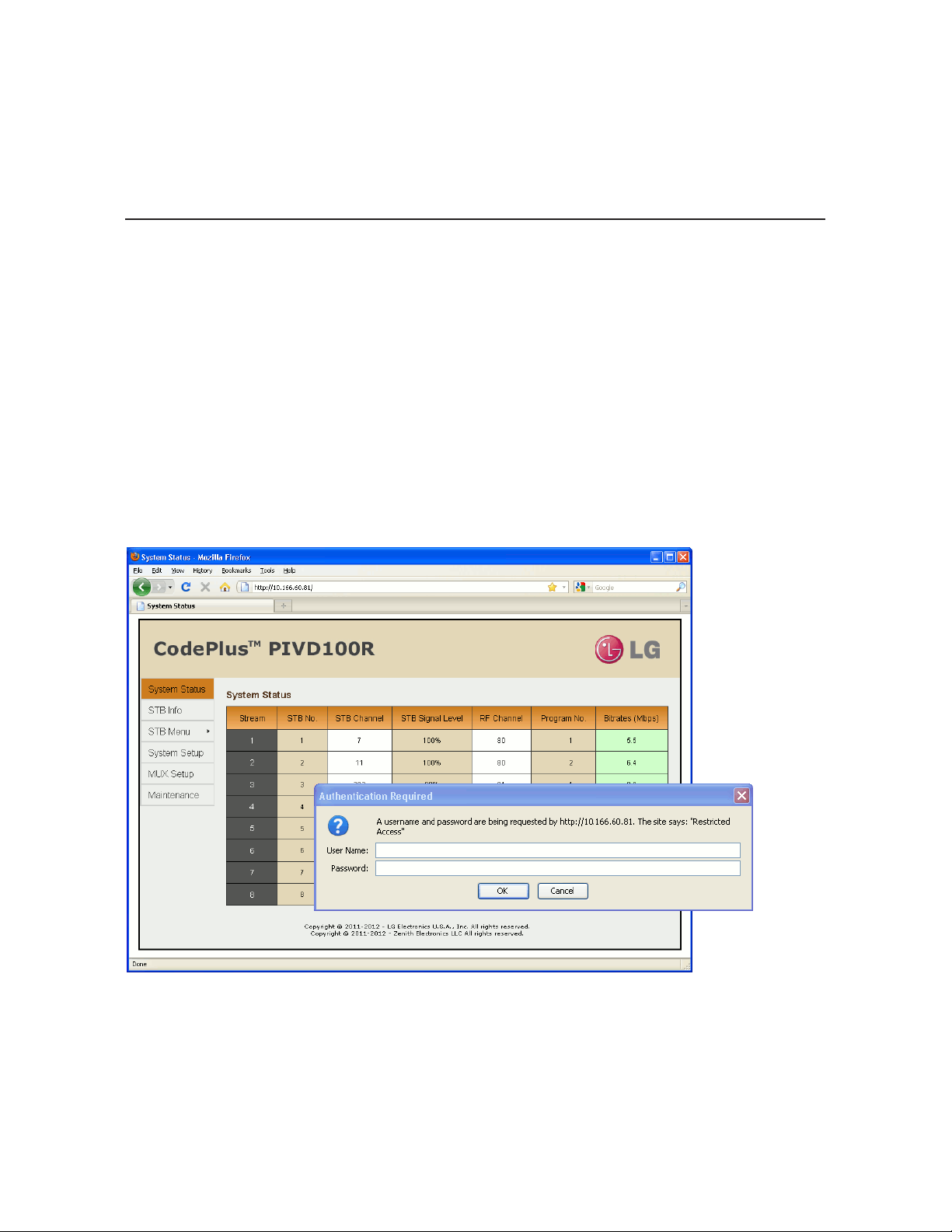
1. Launch a web browser, and type http://ipaddress in the browser’s address bar, where
ipaddress is the network IP address of the PIVD100R. Then, press Enter.
2. The system will display a login authentication pop-up window. In the User Name eld, type
admin; in the Password eld, type the admin user password. Then, click OK.
The PIVD100R web GUI opens with the System Status on display (see “PIVD100R System
Status” on the next page for further information). The options panel at the left of the screen
enables you to view and congure system settings. The following sections provide detailed
information on the configuration settings and commands.
Note: The System Status screen above shows a typical DIRECTV system with RF output data.
Note: It is possible, if desired, to change the login password via the command line interface
Setup Menu “pwd” command as described on page 56.
When you have completed your activities in the PIVD100R web GUI, it is recommended
that you close your browser to prevent unauthorized access to the system.
206-4202
21
Page 22

Conguration Options via GUI (Cont.)
PIVD100R System Status
For each transport stream (one per COM 23 STB or two per ViP 222/ViP 222k STB), the
System Status screen identies the STB number, the STB channel, the STB signal level, and
the streaming bitrates. Depending on the output mode, the display also identies (for each
stream) either the RF channel and program number or the multicast IP address and port number.
From the System Status screen, you can click on an STB channel number to access the
STB Menu for the selected STB. Also, you can click on an RF channel number or multicast
IP address, depending on the output mode, to access the System Setup screen and menu
options for the PIVD100R. Refer to “STB Menu Options” on pages 24 to 27 for information on
the STB Menu and “PIVD100R System Setup Options” on pages 27 to 32 for information on
the System Setup display and menu options.
To view the System Status data at any time while you are working in the web GUI, click on
System Status in the options panel at the left of the screen.
22
Typical System
Status Screen
(DISH Network
system with IP
output data)
206-4202
Page 23

yellow
red
green
yellow
red
yellow
red
Conguration Options via GUI (Cont.)
The STB Signal Level and Bitrates columns refresh every 30 seconds with the latest data. If
a bitrates value is shown with a
operating range; if the bitrates value is shown with a
sion may be too slow (i.e., between 0.2 and 2 Mbps); and if the bitrates value is shown with a
red
background, there is little to no data transmission (under 0.2 Mbps). If an STB is powered
OFF, the Bitrates column will show “N/A.”
Note: The System Status screen above shows a typical DISH Network system with IP output
data. If a DISH Network system is configured for RF output, the System Status screen will
show up to 12 streams (four channels with three programs each). If an additional STB (one or
two) is installed for spare purposes, you will be able to see the spare(s) in the STB Information
screen described below.
STB Information
For each STB connected to the PIVD100R, the STB Information screen identies the STB
channel number, the STB signal level, the streaming bitrates (color coded as described
above), the STB serial number, and the link status (UP or DOWN). For COM 23 STBs, the
screen will also identify the STB access card number and the activation status of the STB
(Activated or N/A), while for ViP 222/ViP 222k STBs, the screen will identify the STB smart
card number and the STB software version.
From the STB Information screen, you can click on an STB channel number to access the
STB Menu for the selected STB. Refer to “STB Menu Options” on pages 24 to 27 for
information on the STB Menu
To view the STB information data at any time while you are working in the web GUI, click on
STB Info in the options panel at the left of the screen.
green
background, the data transmission is within a standard
yellow
background, the data transmis-
206-4202
Typical STB
Information
Screen
23
Page 24

Conguration Options via GUI (Cont.)
STB Menu Options
The STB Menu screen enables you to view and/or modify the STB conguration. To access
the STB Menu for a selected STB, either:
• Click on the desired STB channel number in the System Status or STB Information screen, or
• Click on STB Menu in the options panel at the left of the screen, and then select the
appropriate STB number from the submenu (see below).
On the left side of the STB Menu screen, an Information section displays STB status and
configuration data. On the right side of the STB Menu screen, several menu options are
available, as described in the following subsections.
Typical STB
Menu Screen
(COM 23 Satellite
STB)
24
206-4202
Page 25

Conguration Options via GUI (Cont.)
Typical STB
Menu Screen
(ViP 222k Satellite
STB)
Set the STB/Tuner Channel
In the Change Channel section of the STB Menu screen, you can specify the appropriate
channel number(s) for the STB.
• COM 23 STBs: Type the desired channel number in the Tuner 1 Channel eld. Then, click
on the Set button at the right of the eld.
• ViP 222 or ViP 222k STBs: Type the desired channel number in the Tuner 1 Channel and/or
Tuner 2 Channel elds. Then, click on the Set button at the right of the Tuner 1 Channel eld.
If the channel(s) is/are set successfully, the system will display at the bottom of the
STB Information display.
Note: The system does not determine whether a particular channel is valid/authorized for
your system; it only determines if a “Change Channel” operation is successful. See also note
below.
206-4202
25
Page 26

Conguration Options via GUI (Cont.)
Note: It may take a few minutes before a channel change registers in the system. During the
transition period for the channel change, or if the channel is not valid and thus the STB cannot
tune to the selected channel, the System Status, STB Information, and STB Menu screens will
all show indication of a transition in the STB Channel column/eld, for example:
Note: If you set/change a ViP 222/ViP 222k STB/tuner channel, it is recommended that
you check one or more room receivers to make sure the new channel is tuning properly. If
you see a blank screen or a “No Signal” message on a receiver, use the “reset” command
described on the following page to reset the STB.
Power the STB On or Off
In the STB Power section of the STB Menu screen, you can power ON the STB from standby
mode or power OFF the STB to standby mode.
• To power ON the STB from standby, click on the On button.
• To power OFF the STB, i.e., to switch the STB to standby, click on the Off button.
In each case, if the action is completed successfully, the system will display
bottom of the STB Information display.
at the
Schedule an STB Software Update (ViP 222 or ViP 222k STBs Only)
In the STB Software Update section of the STB Menu screen, you can schedule a software
update for ViP 222 and ViP 222k STBs. The STB Software Update feature enables the STB to
check for and download software updates on a one-time, user-dened basis. An STB Update
should periodically be scheduled in conjunction with software updates from the satellite service
provider.
Note: If you intend to schedule an STB software update, make sure the time is
set on the PIVD100R. See “Date and Time Conguration” on page 31 for further
information.
Note: At the time an update is scheduled to begin, the PIVD100R will switch the
STB(s) to standby in order to enable it/them to download the update. When the 30
minutes allowed for the update window is over, the PIVD100R will power the STB(s)
back ON; however, note that it may take up to 10 minutes for streaming to resume.
Contact your service provider for further information.
1. Select the appropriate STB Software Update status—Enable or Disable (default)—by
clicking the radio button at the left of the desired option.
(Continued on next page)
26
206-4202
Page 27

Conguration Options via GUI (Cont.)
(Continued from previous page)
2. If you enabled the STB Software Update in step 1, complete each of the date and time
elds to set the parameters for the STB update. Click on the down arrow at the right of
each eld (Year, Month, Day, Hour, Minute) to select the appropriate value from the dropdown list of options.
Note: It is recommended that you schedule the 30-minute STB software update window
during a time when the STB is not likely to be in use.
3. If you wish to apply the new enabled/disabled status, and if applicable, the data and time
data, to all of the STBs connected to this PIVD100R, click the “Apply to all other STBs”
checkbox.
4. When you have completed the fields as required, click on the Set button at the bottom of the
STB Software Update section to confirm your settings.
If you successfully set the STB Software Update status/parameters, the system will display
at the bottom of the STB Information display.
Reset the STB
1. Click on the Reset button in the Reset STB section of the STB Menu screen.
2. The system will display a pop-up window prompting for confirmation. Either:
• Click OK to proceed.
• Click Cancel to return to the STB Menu screen without resetting the STB.
If you opt to proceed, the system will initiate the reset immediately. Note that an STB reset
may take up to 10 minutes. After reset, the STB resumes normal operation.
PIVD100R System Setup Options
The System Setup screen enables you to view and/or modify the system conguration. To
access the System Setup screen, click on System Setup in the options panel at the left of the
screen.
On the left side of the System Setup screen, the System Information section provides important
information about the current configuration of the PIVD100R, including the unit serial number,
software version, hardware ID (firmware version), Control Port MAC and IP addresses, and
output configuration. On the right side of the screen, several menu options are available, as
described in the following subsections.
206-4202
27
Page 28

Conguration Options via GUI (Cont.)
Typical System
Setup Screen
28
206-4202
Page 29

Conguration Options via GUI (Cont.)
Select the STB Type
1. In the STB Type section of the System Setup screen, click the radio button at the left of the
appropriate service provider for your system, and then click on the Set button.
If you successfully changed the STB type, the system will display
at the bottom of the System Information display. The System Information display will also
show the new STB type.
2. Click on the Reset button in the System Reset section of the System Setup screen if you
are ready to reset the system immediately (see “Reset the System” on page 32 for further
information).
Note: If you intend to modify additional conguration settings during the current session,
you may wait until all changes are complete before you reset the system.
Control Port Configuration
In the Control Port IP Conguration section of the System Setup screen, you can modify the
Control Port IP conguration as required.
1. Select the appropriate DHCP Mode—Enable (default) or Disable—by clicking the radio
button at the left of the desired option.
Note: If DHCP is enabled, the server assigns an IP address to the PIVD100R, and only the
Hostname eld will be editable. All other elds will be inaccessible/grayed out.
2. If desired, modify the name of the host in the Hostname eld.
3. If DHCP is disabled, specify the host IP address, the subnet mask, the default gateway IP
address, the primary DNS IP address, and the secondary DNS IP address in the fields
provided. Type each in the format xxx.xxx.xxx.xxx.
4. When you have completed the fields as required, click on the Set button below the
Secondary DNS IP Address field.
If you successfully changed the IP configuration of the Control Port, the system will display
at the bottom of the System Information display. The System
Information display will also show the new Control Port IP address, if applicable.
5. Click on the Reset button in the System Reset section of the System Setup screen if you
are ready to reset the system immediately (see “Reset the System” on page 32 for further
information).
Note: If you intend to modify additional conguration settings during the current session,
you may wait until all changes are complete before you reset the system.
206-4202
29
Page 30

Conguration Options via GUI (Cont.)
Output Mode Configuration
In the Output Mode section of the System Setup screen, you can modify the PIVD100R output
conguration (see RF and IP output conguration examples below).
Example: RF Output Configuration Field
Example: IP Output Configuration Fields
Complete output configuration as follows:
1. Select the Output Mode—RF or IP—by clicking the radio button at the left of the appropriate
option.
Note: Depending on the current configuration of the system, when you access the System
Setup screen, either the RF Output Configuration or IP Output Configuration field(s) initially
will be on display below the Output Mode options. If you select a new mode, the system will
display the applicable field(s) per your selection.
(Continued on next page)
30
206-4202
Page 31

Conguration Options via GUI (Cont.)
(Continued from previous page)
2. The next step depends on the output mode selected:
• For RF output conguration: In the Start RF Channel eld, type the RF start channel
number. The remaining three channels will be automatically assigned per EIA-542 STD
CATV frequency allocation standards.
• For IP output conguration: For each IP channel stream (one per COM 23 STB or two per
ViP 222/ViP 222k STB), type the appropriate multicast IP address and port number in the
IP Address and IP Port elds, respectively.
Note: The IP Output Configuration Fields example above shows IP output configuration
fields for a COM 23 STB, with one program per stream. If the system is configured for
ViP 222/ViP 222k STBs, you will need to specify two programs per stream.
Note: If you would like to have the PIVD100R auto-increment IP channels from a base
multicast IP address, you will need to complete output IP channel configuration from
the command line interface. See “Configure the IP Output” on pages 50 to 53 for further
information.
3. When you have completed the field(s) as required, click on the Set button at the right of the
Start RF Channel field or below the last IP Port field, as applicable.
If you successfully changed output configuration parameters, the system will display
at the bottom of the System Information display. The System Information display will also show
the updated output conguration.
Date and Time Configuration
If your system is congured with ViP 222/ViP 222k STBs, you may want to set the date and
time on the PIVD100R for the purposes of scheduling STB software updates (see “Schedule
an STB Software Update” on page 26 for further information).
By default, the PIVD100R is synchronized with an NTP client and congured for the Central
time zone. If the PIVD100R is connected to the Internet, the NTP client will periodically update
the time setting on the PIVD100R. If the PIVD100R is not connected to the Internet, you also
have the option to disable NTP client synchronization and specify date and time data manually.
1. Click on the down arrow at the right of the Time Zone eld in the Time Conguration
section of the System Setup screen, and select the appropriate time zone from the dropdown list of options.
2. Select the appropriate NTP setting—Enable or Disable—by clicking the radio button at the
left of the appropriate option.
Note: Per your selection, certain of the Time Conguration elds will become inaccessible/
grayed out. If NTP is enabled, Data and Time elds will be grayed out; if NTP is disabled,
the NTP Server eld will be grayed out.
(Continued on next page)
206-4202
31
Page 32

Conguration Options via GUI (Cont.)
(Continued from previous page)
3. The next step depends on whether you enabled or disabled NTP:
• If you enabled NTP, type the IP address of the NTP server in the NTP Server eld.
• If you disabled NTP, complete the Date and Time elds to manually specify the date and
time for the PIVD100R. Click on the down arrow at the right of each eld (Year, Month,
Day, Hour, Minute) to select the appropriate value from the drop-down list of options.
4. When you have completed the fields as required, click on the Set button at the bottom of
the Time Conguration section.
If you successfully changed the PIVD100R time configuration, the system will display
at the bottom of the System Information display. The System
Information display will also show the updated information in the Time Zone and Current
Time elds, as applicable.
5. Click on the Reset button in the System Reset section of the System Setup screen if you
are ready to reset the system immediately (see “Reset the System” below for further
information).
Note: If you intend to modify additional conguration settings during the current session,
you may wait until all changes are complete before you reset the system.
Reset the System
1. Click on the Reset button in the System Reset section of the System Setup screen.
2. The system will display a pop-up window prompting for confirmation. Either:
• Click OK to continue.
• Click Cancel to return to the System Setup screen without resetting the PIVD100R.
If you opt to proceed, this will initiate a reset of the PIVD100R and may also initiate a reset of
one or more STBs, if required. Once the PIVD100R is reset (may take up to 90 seconds), it
may then take up to 10 minutes for the system to resume normal operation.
MUX Setup Options
The MUX Setup screen enables you to reset or recongure STB/output assignments. To
access the MUX Setup screen, click on MUX Setup in the options panel at the left of the
screen.
32
206-4202
Page 33

Conguration Options via GUI (Cont.)
Typical MUX
Setup Screen
Reset STB/Output Assignments
To reset the previous, i.e., last stored, STB/output assignments, click on the Reset button at
the bottom of the Stream column. The STB/output assignments will be reset immediately.
Modify STB/Output Assignments
1. Click on the down arrow at the right of each STB eld you wish to reassign, and select
from the drop-down list of options the appropriate STB number or N/C (no connection) for
the stream listed in the Stream column. Note that each STB can only be assigned to one
stream (DIRECTV) or one pair of streams (DISH Network).
2. When you have completed the assignments, click on the Set button at the bottom of the
STB column.
3. The system will display a pop-up window prompting for confirmation of the changes. Either:
• Click OK to conrm and apply the new assignments.
• Click Cancel to return to the MUX Setup screen without saving your changes.
If you successfully change the STB/output assignments, the system will display
below the MUX Setup screen.
206-4202
33
Page 34

Conguration Options via GUI (Cont.)
PIVD100R Maintenance Options
The Maintenance screen enables you to reload the Pro:Idiom key, update rmware, and reset
the system. To access the Maintenance screen, click on Maintenance in the options panel at
the left of the screen.
Typical
Maintenance
Screen
Reload the Pro:Idiom Key
A password is required to initiate a Pro:Idiom key reload. If necessary, obtain the password
from the system administrator before beginning this procedure.
Note: If this is the first time the Pro:Idiom key will be reloaded, contact LG for the password.
1. Click on the Reload button in the Pro:Idiom Key Reload section of the Maintenance screen
to reload the Pro:Idiom key on the TVs.
(Continued on next page)
34
206-4202
Page 35

Conguration Options via GUI (Cont.)
(Continued from previous page)
The system will display a pop-up window prompting for the password required to reload the
Pro:Idiom key.
2. Either:
• Type the password and click OK to continue.
• Click Cancel to return to the Maintenance screen without reloading the Pro:Idiom key.
If you opt to proceed, the system will execute the key reload immediately and display results
in the Result section at the bottom of the screen, for example:
Note: If you wish to install a new Pro:Idiom key or change the password required for
reloading a Pro:Idiom key, it must be done via the command line interface. See “Pro:Idiom
Menu Commands” on pages 58 to 60 for further information.
Update the PIVD100R Firmware
The appropriate update le must be provided by LG. The system will not download an
improper le.
1. In the Firmware Update section of the Maintenance screen, either click on the Browse
button at the right of or simply click in the Filename field, and navigate to/select the
appropriate file from the File Upload pop-up window.
2. Once you have selected the appropriate file, click on the Upload button below the Filename field to initiate the firmware update.
3. The system will display a pop-up window prompting for confirmation to update the system.
Either:
• Click OK to continue.
• Click Cancel to return to the Maintenance screen without updating the PIVD100R
rmware.
(Continued on next page)
206-4202
35
Page 36

Conguration Options via GUI (Cont.)
(Continued from previous page)
If you opt to proceed, the system will initiate the firmware update, and progress and results
messages will be displayed in the Result section at the bottom of the screen, for example:
4. When the rmware update is nished, click on the Reset button in the System Reset
section of the Maintenance screen to reset the system (see “Reset the System” below for
further information).
Check Firmware Update Status
In the Firmware Update section of the Maintenance screen, click on the Status button to
check the current firmware update status.
The system will display firmware update status (for example, “Firmware Update finished” or
“Firmware Update is in progress”) in the Result section at the bottom of the screen. If a
firmware update has never been performed on this system, the Result display will show:
Reset the System
1. Click on the Reset button in the System Reset section of the Maintenance screen.
2. The system will display a pop-up window prompting for confirmation. Either:
• Click OK to continue.
• Click Cancel to return to the Maintenance screen without resetting the PIVD100R.
If you opt to proceed, this will initiate a reset of the PIVD100R and may also initiate a reset of
one or more STBs, if required. Once the PIVD100R is reset (may take up to 90 seconds), it
may then take up to 10 minutes for the system to resume normal operation.
36
206-4202
Page 37

Conguration Options via Command Line
Log In to the PIVD100R and Access the Main Menu
Note: The PIVD100R must be connected to an IP network for SSH client access. For direct
access to the PIVD100R Service Port, use the FTDI TTL-USB cable (P/N TTL-232R-5V-AJ).
See also “Network and Communication Setup” on page 20 for further information.
If necessary, consult the system administrator to obtain the current “admin” user password
before proceeding. The default admin user password is “Password4Partners” (case-sensitive).
1. Establish communication with the PIVD100R using an SSH client or via a direct connection
to the PIVD100R Service Port.
Once communication is established, you should see a login prompt. (If the login prompt is
not automatically displayed, press Enter to refresh the screen.)
2. At the
3. At the
4. At the
The following sections describe each of the configuration commands.
Note: You can always press Enter at the
Menu.
login as:
password:
Command >
• Press Enter to display the PIVD100R Main Menu (see example below).
• Type the desired command and press Enter.
prompt, type admin and press Enter.
prompt, type the admin user password and press Enter.
prompt, either:
Command >
prompt to display the PIVD100R Main
Example: PIVD100R Main Menu
---------
Main Menu
---------
info System information
monitor System monitor
stb STB Menu
setup Setup Menu
update Update Menu
pi Pro:Idiom Menu
reset System reset
exit End session
Command >
206-4202
37
Page 38

Conguration Options via Command Line (Cont.)
View System Information
1. Log in to the PIVD100R as described on the previous page.
2. At the
The System Information display identies important information about the PIVD100R,
including the unit serial number, software version, hardware ID (rmware version), Control
Port MAC and IP addresses, and output conguration, for example:
PIVD100R
Pro:Idiom Video Distribution Transcoder System
Copyright (c) 2010-2012 LG Electronics U.S.A, Inc.
Copyright (c) 2010-2012 Zenith Electronics LLC
SN: 101-12470001
Version 1.5
HW id: 3-207-79-4
Ctrl MAC: 00:0C:63:3B:00:BE
Ctrl IP: 136.166.60.92
STB Type: DirecTV
Output: RF
RF config: Mode 2, QAM-B, RF: 6 MHz, 5.36 MSps
RF channels: 3 4 5 6
Local time: Thu Mar 22 14:42:02 CDT 2012
Command >
prompt, type info and press Enter.
Note: If the system is configured for IP output, the Output field will show “IP” and RF fields
will not be present.
It is recommended that you record this information for future reference. If you find it
necessary to call customer service or engineering support, please have this information
available.
Monitor the System
This option enables you to view static or dynamic system streaming data.
1. Log in to the PIVD100R as described on the previous page.
2. At the
38
Command >
• Type monitor and press Enter to display the current system data (see examples on the
following page).
• To monitor streaming data in real time, type monitor and the number of seconds before
the data refreshes. Then, press Enter. For example, to refresh the data every second,
type monitor 1 and press Enter.
When you are nished monitoring streaming data, press Enter to stop the system
monitor and return to the
prompt, either:
Command >
prompt.
206-4202
Page 39

Conguration Options via Command Line (Cont.)
Example: System Monitor Display (DIRECTV STB/RF Output)
SYSTEM MONITOR
Date: 2012-02-16 16:44:27
STB type: DirecTV
Output: RF
Bitrates (Mbps):
------+------------+------+------+------+-----+------- STB | Channel | Sig | Lck | Out | Str | RF
------+------------+------+------+------+-----+------- 1-1 | 7 | 100 | Yes | 5.1 | 1 | 60-1 :)
2-1 | 11 | 100 | Yes | 12.2 | 2 | 60-2 :)
3-1 | 202 | 90 | Yes | 8.8 | 3 | 61-1 :)
4-1 | 206 | 96 | Yes | 6.8 | 4 | 61-2 :)
5-1 | 215 | 93 | Yes | 10.4 | 5 | 62-1 :)
6-1 | 218 | 94 | Yes | 8.8 | 6 | 62-2 :)
7-1 | 269 | 95 | Yes | 3.7 | 7 | 63-1 :)
8-1 | 504 | 93 | Yes | 9.5 | 8 | 63-2 :)
------+------------+------+------+------+-----+--------
Use a parameter for auto-refresh, e.g. type: “monitor 1”
Example: System Monitor Display (DISH Network STB/IP Output)
SYSTEM MONITOR
Date: 2012-02-21 19:05:20
STB type: Dish
Output: IP
Bitrates (Mbps):
------+------------+------+------+------+-----+--------------+------- STB | Channel | Sig | Lck | Out | Str | IP | Port
------+------------+------+------+------+-----+--------------+------- 1-1 | 2 | 50 | Yes | 4.9 | 1 | 227.0.0.0 | 1234 :)
1-2 | 5 | 51 | Yes | 6.2 | 2 | 227.0.0.1 | 1234 :)
2-1 | 7 | 52 | Yes | 4.9 | 3 | 227.0.0.2 | 1234 :)
2-2 | 9 | 52 | Yes | 4.6 | 4 | 227.0.0.3 | 1234 :)
3-1 | 105 | 51 | Yes | 4.4 | 5 | 227.0.0.4 | 1234 :)
3-2 | 112 | 51 | Yes | 3.8 | 6 | 227.0.0.5 | 1234 :)
4-1 | 119 | 53 | Yes | 3.4 | 7 | 227.0.0.6 | 1234 :)
4-2 | 120 | 51 | Yes | 4.5 | 8 | 227.0.0.7 | 1234 :)
5-1 | 138 | 52 | Yes | 4.0 | 9 | 227.0.0.8 | 1234 :)
5-2 | 139 | 52 | Yes | 5.9 | 10 | 227.0.0.9 | 1234 :)
6-1 | 140 | 51 | Yes | 3.6 | 11 | 227.0.0.10 | 1234 :)
6-2 | 144 | 51 | Yes | 6.2 | 12 | 227.0.0.11 | 1234 :)
7-1 | 160 | 52 | Yes | 4.1 | 13 | 227.0.0.12 | 1234 :)
7-2 | 176 | 53 | Yes | 5.3 | 14 | 227.0.0.13 | 1234 :)
8-1 | 205 | 50 | Yes | 6.2 | 15 | 227.0.0.14 | 1234 :)
8-2 | 206 | 52 | Yes | 3.7 | 16 | 227.0.0.15 | 1234 :)
------+------------+------+------+------+-----+--------------+--------
Use a parameter for auto-refresh, e.g. type: “monitor 1”
206-4202
39
Page 40

Conguration Options via Command Line (Cont.)
STB Menu Commands
The following subsections describe how to access and use the STB Menu commands.
Access the STB Menu
1. Log in to the PIVD100R as described on page 37.
2. At the
3. At the
4. At the
Note: You can always press Enter at the
Menu.
Command >
Enter STB number >
connected to the STB for which you wish to view/modify configuration. Then, press Enter.
The system identifies the current STB and then displays an STB command prompt, for
example:
prompt, type stb and press Enter.
prompt, type the number of the PIVD100R X-Port
Current STB: STB-1
STB-1 Command >
STB Command >
• Press Enter to display the STB Menu (see example below).
• Type the desired command and press Enter.
prompt, either:
STB Command >
prompt to display the STB
Example: STB Menu
---------
STB Menu
---------
stb Change STB
info STB info
monitor System monitor
channel Set channel
output Output slot
on Turn STB On
off Turn STB Off (Standby)
update Schedule STB software update
reset Reset STB
exit Return to the main menu
STB-1 Command >
40
206-4202
Page 41

Conguration Options via Command Line (Cont.)
Change STB
This command enables you to switch to the STB Menu for another STB.
1. At the
2. At the
View STB Information
At the
configuration data (see examples below).
Example: STB Information (COM 23 Satellite STB)
STB Command >
Enter STB number [#]>
connected to the STB for which you wish to view/modify configuration. Then, press Enter.
The system will identify the (newly) current STB and then display a command prompt, for
example:
prompt, type stb and press Enter.
prompt, type the number of the PIVD100R X-Port
Current STB: STB-3
STB-3 Command >
STB Command >
prompt, type info and press Enter to display STB status and
STB-1 Info
===========
Output: 1
Receiver N: 029267852837
Card N: 002528994052
Activated: Yes
Channel: 215
Locked: Yes
Signal level: 93
Example: STB Information (ViP 222k Satellite STB)
STB-1 Info
===========
Output: 1
Receiver N: R0128390262-81
Card N: S1959036673-74
STB Model: ViP222k-HD
STB SW ver: X397RPDB-N
SW Update: 2012-03-05 11:56:00
Tuner 1
Channel: 2
Locked: Yes
Signal lvl: 75
Tuner 2
Channel: 5
Locked: Yes
Signal lvl: 80
206-4202
41
Page 42

Conguration Options via Command Line (Cont.)
Monitor the System
This option enables you to view static or dynamic system streaming data and is also available
from the PIVD100R Main Menu and the Setup Menu.
At the
STB Command >
• Type monitor and press Enter to display the current system data (see sample displays
under the “Monitor the System” section on page 38).
• To monitor streaming data in real time, type monitor and the number of seconds before
the data refreshes. Then, press Enter. For example, to refresh the data every second, type
monitor 1 and press Enter.
When you are nished monitoring streaming data, press Enter to stop the system monitor
and return to the
Set the STB/Tuner Channel
1. At the
2. (Dual tuner STB only) At the
3. At the
STB Command >
press Enter to accept the default value in square brackets, or type the appropriate tuner
number and press Enter.
Enter channel [7]>
• Press Enter to accept the default value in square brackets, or
• Type in a new channel number and then press Enter.
prompt, either:
STB Command >
prompt, type channel and press Enter.
Enter tuner number (1 or 2) [1]>
prompt, either:
prompt.
prompt, either
The system will display confirmation, for example:
Channel: 8 or Tuner: 1 Channel: 2
Note: The system does not determine whether a particular channel is valid/authorized for your
system; it only determines if a “Set Channel” operation is successful. See also note below.
Note: It may take a few minutes before a channel change registers in the system. During the
transition period for the channel change, or if the channel is not valid and thus the STB cannot
tune to the selected channel, the System Monitor will show indication of a transition in the
Channel column, for example:
Note: If you set/change a ViP 222/ViP 222k STB/tuner channel, it is recommended that you
check one or more room receivers to make sure the new channel is tuning properly. If you
see a blank screen or a “No Signal” message on a TV, use the “reset” command described
on page 45 to reset the STB.
42
7 -> 2
.
206-4202
Page 43

Conguration Options via Command Line (Cont.)
Configure STB/Output Assignments
This option enables you to recongure STB/output assignments. Note that each STB can
only be assigned one output stream (DIRECTV) or one pair of streams (DISH Network). If
you remap an existing stream assignment to another STB X-Port, the initial assignment will
be disconnected.
For example: If STB 1 is currently streaming on output 1, and STB 2 is remapped so that it
is streaming on output 1, the initial STB 1 assignment will be disconnected. If all STBs are
currently assigned to output streams, STB 1 will now be assigned the output that was
previously assigned to STB 2. If STB 2 initially had “no connection” status before it was
remapped to output 1, STB 1 will now have “no connection” status.
If you wish to remap an existing stream or pair of streams to another STB, it is recommended
that you rst modify the output assignment of the stream in question to “no connection” before
you reassign the stream as required.
1. At the
2. (Dual tuner STB only) At the
3. At the
STB Command >
press Enter to accept the default value in square brackets, or type the appropriate tuner
number and press Enter.
prompt, type output and press Enter.
Enter tuner number (1 or 2) [1]>
prompt, either
Enter output slot number (1-8 or 0 for no connect) [slot#]>
prompt, either:
• Press Enter to accept the default (slot#) value in square brackets.
• Type 0 and press Enter to specify “no connection.”
• Type in a slot number (1–8) and press Enter to remap the output stream to a different
STB/X-Port.
The system will display confirmation, for example:
Output slot remapped. STB is now streaming on output 2
Note: You can run the “monitor” command, if desired, to review the system settings. Refer to
“Monitor the System” on the previous page for further information.
Power the STB On or Off
These commands enable you to power ON the STB from standby mode or power OFF the
STB to standby mode.
At the
STB Command >
• Type on and press Enter to power ON the STB from standby. The system will display
conrmation, for example:
prompt, either:
Powering on STB-1: OK
• Type off and press Enter to power OFF the STB, i.e., to switch the STB to standby. The
system will display conrmation, for example:
Powering off STB-1: OK
206-4202
43
Page 44

Conguration Options via Command Line (Cont.)
Schedule an STB Software Update (ViP 222 or ViP 222k STBs Only)
This option is available only for ViP 222 and ViP 222k STBs. The STB Software Update feature
enables the STB to check for and download software updates on a one-time, user-dened
basis. An STB Update should periodically be scheduled in conjunction with software updates
from the satellite service provider.
Note: If you intend to schedule an STB software update, make sure the time is set
on the PIVD100R. See “Set the Time Zone” and “Set the Date and Time” on pages
53 to 55 for further information.
Note: At the time an update is scheduled to begin, the PIVD100R will switch the
STB(s) to standby in order to enable it/them to download the update. When the 30
minutes allowed for the update window is over, the PIVD100R will power the STB(s)
back ON; however, note that it may take up to 10 minutes for streaming to resume.
Contact your service provider for further information.
1. At the
2. At the
STB Command >
Enable STB software update? [y/n]:
• Type y and press Enter to enable an STB software update. The system will initiate a
series of prompts that enable you to congure the date and time parameters for the
update. Continue with step 3.
• Type n and press Enter to disable the STB software update. At the
all other STBs? [y/n]:
- Type y and press Enter to disable a scheduled STB software update on all STBs
connected to the PIVD100R, or
- Type n and press Enter to disable a scheduled STB software update on the current
STB only.
The system will display conrmation of your setting, for example:
prompt, type update and press Enter.
prompt, either:
Also disable for
prompt, either:
STB-1 SW Update: not scheduled
3. At each of the following prompts, type the year, month, and day, respectively, on which you
wish to schedule the STB software update. Note that all three of these elds require
numerical values. Press Enter after each entry.
If applicable, you can also press Enter at each prompt to accept the default value in
square brackets.
Enter year [2012]>
Enter new month [2]>
Enter new day [22]>
(Continued on next page)
44
206-4202
Page 45

Conguration Options via Command Line (Cont.)
(Continued from previous page)
4. At each of the following prompts, type the hour and minute, respectively, at which you wish
to schedule the STB software update. Note that the hour should be entered in 24-hour
format. Press Enter after each entry.
If applicable, you can also press Enter at each prompt to accept the default value in square
brackets.
Enter new hour [3]>
Enter new minute [0]>
Note: It is recommended that you schedule the 30 minute STB software update window
during a time when the STB is not likely to be in use.
5. At the
The system will display conrmation of your setting, for example:
STB-1 SW Update: 2012-02-22 03:00:00
Also schedule for all other STBs? [y/n]:
• Type y and press Enter to enable the scheduled STB software update on all STBs
connected to the PIVD100R, or
• Type n and press Enter to enable the scheduled STB software update on the current
STB only.
prompt, either:
Reset the STB
At the
STB Command >
the STB. Note that an STB reset may take up to 10 minutes.
Exit the STB Menu
At the
STB Command >
to the PIVD100R Main Menu
prompt, type reset and press Enter to initiate an immediate reset of
prompt, type exit and press Enter to exit the STB Menu and return
Command >
prompt.
Setup Menu Commands
The following subsections describe how to access and use the Setup Menu commands.
Access the Setup Menu
1. Log in to the PIVD100R as described on page 37.
2. At the
3. At the
Note: You can always press Enter at the
Menu.
206-4202
Command >
Setup Command >
• Press Enter to display the Setup Menu (see example on following page).
• Type the desired command and press Enter.
prompt, type setup and press Enter.
prompt, either:
Setup Command >
prompt to display the Setup
45
Page 46

Conguration Options via Command Line (Cont.)
Example: Setup Menu
----------
Setup Menu
----------
info System information
monitor System monitor
type Set STB type
omode Set output mode
setip Control port IP configuration menu
rf RF output configuration
ipout IP output configuration menu
tz Timezone setup
time Time setup
pwd Change password
exit Return to the main menu
reset System reset
Setup Command >
View System Information
This option is also available from the PIVD100R Main Menu.
At the
Setup Command >
The System Information display identies important information about the PIVD100R,
including the unit serial number, software version, hardware ID (rmware version), Control
Port MAC and IP addresses, and output conguration. See sample display under the “View
System Information” section on page 38.
It is recommended that you record this information for future reference. If you nd it necessary
to call customer service or engineering support, please have this information available.
Monitor the System
This option enables you to view static or dynamic system streaming data and is also available
from the PIVD100R Main Menu and the STB Menu.
At the
Setup Command >
• Type monitor and press Enter to display the current system data (see sample displays
under the “Monitor the System” section on page 38).
• To monitor streaming data in real time, type monitor and the number of seconds before
the data refreshes. Then, press Enter. For example, to refresh the data every second, type
monitor 1 and press Enter.
When you are nished monitoring streaming data, press Enter to stop the system monitor
and return to the
Setup Command >
prompt, type info and press Enter.
prompt, either:
prompt.
46
206-4202
Page 47

Conguration Options via Command Line (Cont.)
Select the STB Type
1. At the
2. At the prompt, either press Enter to accept the default value (i.e., the current setting) in
3. If prompted to do so, make sure to reset the system before you exit the current session. If
Setup Command >
The system will display a list of the available STB types, followed by a prompt for the new
STB type, for example:
prompt, type type and press Enter.
Available STB types:
1 - Dish
2 - DirecTV
Enter number of new STB type [1]>
square brackets, or type the number that corresponds to the appropriate STB type and
press Enter.
The system will conrm your selection. If you change the STB type, you will also be
prompted to reset the PIVD100R, for example:
STB type is set: DirecTV
Please reset the system
you are ready to reset the system immediately, at the
reset and press Enter (see “Reset the System” on page 56 for further information).
Note: If you intend to modify additional conguration settings during the current session,
you may wait until all changes are complete before you reset the system.
Setup Command >
prompt, type
Set the Output Mode
1. At the
Setup Command >
The system will display a list of the available output modes, followed by a prompt for the
new output mode, for example:
prompt, type omode and press Enter.
Available output modes:
1 - RF
2 - IP
Enter number of new output mode [1]>
2. At the prompt, either press Enter to accept the default value (i.e., the current setting) in
square brackets, or type the number that corresponds to the appropriate output mode and
press Enter.
The system will conrm your selection, for example:
Output mode is set: RF
3. Complete the appropriate conguration, depending on the output mode. Refer to “Congure
the RF Output” on page 50 or “Congure the IP Output” on pages 50 to 53, as applicable.
206-4202
47
Page 48

Conguration Options via Command Line (Cont.)
Configure the Control Port
1. At the
Setup Command >
The system displays an overview of the current TCP/IP network conguration followed by
the Network Conguration Menu, for example:
prompt, type setip and press Enter.
Current Network Configuration
Interface controller port
Host name: pivd100r
Using DHCP: YES
DNS servers
Primary DNS: 68.94.156.1
Secondary DNS: 68.94.157.1
-------------------------Network Configuration Menu
------------------------- ip Configure Control Port IP
dns Configure DNS
exit Exit network configuration
Choose item to modify >
2. Either:
• Continue with step 3 for information on modifying the IP conguration of the Control Port.
• Go to step 8 for information on modifying the DNS conguration.
• To exit the Network Conguration Menu without modifying any settings, type exit at the
Network Conguration Menu
3. Type ip and press Enter to modify the conguration of the Control Port.
4. At the
5. At the
6. If the PIVD100R is NOT using DHCP, type the information requested at each of the following
Host name [pivd100r]:
square brackets, or type a new host name and then press Enter.
Using DHCP (Y/N) [Y]:
specify the network IP addresses. Then, press Enter.
prompts. Press Enter after each entry.
This host IP address []:
Network mask []:
(Type the netmask in the format xxx.xxx.xxx.xxx.)
Gateway IP address []:
>
prompt.
prompt, either press Enter to accept the default value in
prompt, type y if the PIVD100R uses DHCP, or type n to
(Type the host IP address in the format xxx.xxx.xxx.xxx.)
(Type the IP address of the default gateway in the format xxx.xxx.xxx.xxx.)
(Continued on next page)
48
206-4202
Page 49

Conguration Options via Command Line (Cont.)
(Continued from previous page)
7. Once you enter the gateway IP address, the system will redisplay the Network Configuration
Menu.
• To modify the DNS conguration, continue with step 8.
• If no additional network conguration is required, go to step 9.
8. To change the DNS conguration, type dns and press Enter.
At each of the following prompts, type the information requested. Press Enter after each
entry.
Configuring DNS
Primary DNS IP address []:
Secondary DNS IP address []:
Once you enter the secondary DNS IP address, the system will redisplay the Network
Configuration Menu. You can select another option to modify (see previous steps) or you
can exit as described below.
9. When you are nished with network conguration, type exit at the Network Conguration
Menu
>
prompt. The system will display an overview of the new network conguration
and then prompt for conrmation to save the changes, for example:
New Network Configuration
Interface controller port
Host name: pivd100r
Using DHCP: NO
Host IP address: 136.166.60.92
Network mask: 255.255.255.0
Gateway IP address: 136.166.60.1
DNS servers
Primary DNS: 68.94.156.2
Secondary DNS: 68.94.157.2
Do you want to save the new configuration? (Y/N):
10. Type y or n and press Enter, as appropriate.
If you opt NOT to save the new configuration, the system will return immediately to the
Setup Command >
and prompt you to reset the system:
prompt. Otherwise, the system will confirm the configuration updates
New configuration has been saved. Please restart the system.
11. If you are ready to reset the system immediately, at the
reset and press Enter (see “Reset the System” on page 56 for further information).
Note: If you intend to modify additional conguration settings during the current session,
you may wait until all changes are complete before you reset the system.
206-4202
Setup Command >
prompt, type
49
Page 50

Conguration Options via Command Line (Cont.)
Configure the RF Output
This option enables you to specify the appropriate RF channels for your location. See
“Channel Assignments for RF Output” on page 9, and/or check with your service representative,
if necessary.
Note: Ensure the output mode also has been set accordingly. See “Set the Output Mode” on
page 47 for further information.
1. At the
2. At the prompt for the RF mode, either:
3. If you selected the RF output (QAM-B) option in step 2, the system will prompt next for an RF
4. At the
Setup Command >
The system displays a list of the RF mode options and prompts for a selection:
prompt, type rf and press Enter.
RF Setup
Available RF modes are:
1) RF: OFF
2) QAM-B, RF: 6 MHz, 5.36 MSps
(default)
Select a new RF mode [2]:
• Type 1 and press Enter to disable RF output.
• Type 2 and press Enter to enable RF output.
Note: You can simply press Enter if the default shown in square brackets is the correct op-
tion for this system.
channel number (i.e., the RF start channel number):
Enter a new RF channel [3]:
At the prompt, either press Enter to accept the default value in square brackets, or type a
new RF start channel number and then press Enter.
Enter number of channels [4]:
default value in square brackets, or type the applicable number of channels (Maximum = 4).
prompt, either press Enter to accept the
Once you specify the RF setup, the system displays an overview of the settings, for example:
RF config: Mode 2, QAM-B, RF: 6 MHz, 5.36 MSps
RF channels: 7 8 9 10
Configure the IP Output
IP Output Configuration Menu options enable you to view and/or modify the IP output
configuration for your system. Each of the menu options is described below.
Note: Ensure the output mode also has been set accordingly. See “Set the Output Mode” on
page 47 for further information.
50
206-4202
Page 51

Conguration Options via Command Line (Cont.)
Access the IP Output Configuration Menu
1. At the
2. At the
Setup Command >
IP Output Command >
• Press Enter to display the IP Output Conguration Menu (see example below).
• Type the desired command and press Enter.
prompt, type ipout and press Enter.
prompt, either:
---------------------------IP Output Configuration Menu
--------------------------- display Display output IP configuration
set Configure output IP channel
fill Fill IP configuration with autoincrement IP
apply Apply the new IP configuration
exit Return to the Setup Menu
IP Output Command >
Display Output IP Conguration
1. At the
IP Output Command >
current output conguration, for example:
prompt, type display and press Enter to view the
N IP Address Port
--- ------------- ---1-1 227.0.0.0 1234
2-1 227.0.0.2 1234
3-1 227.0.0.4 1234
4-1 227.0.0.6 1234
5-1 227.0.0.8 1234
6-1 227.0.0.10 1234
7-1 227.0.0.11 1234
8-1 227.0.0.12 1234
2. At the
Manually Configure Output IP Channels
This option enables you to specify the multicast IP address and port number for each program.
Each program must be assigned a unique IPv4 multicast address. See “Channel Assignments
for IP Output” on page 9, and/or check with your service representative, if necessary.
Note: If you wish to set a base multicast IP address and have the system auto-increment the
remaining program data, use the “fill” option described below.
1. At the
IP Output Command >
Menu when you are nished reviewing the display.
IP Output Command >
prompt, type exit and press Enter to return to the Setup
prompt, type set and press Enter.
206-4202
(Continued on next page)
51
Page 52

Conguration Options via Command Line (Cont.)
(Continued from previous page)
2. At the
3. (Dual tuner STB only) At the
4. At the
5. At the
6. After you type the port number, the system returns to the
7. When you have set all output IP channels as required, type apply and press Enter at the
8. At the
Auto-configure Output IP Channels
This option enables you to have the system auto-increment the output IP channels from a
base multicast IP address and port number. Each program must be assigned a unique IPv4
multicast address. See “Channel Assignments for IP Output” on page 9, and/or check with your
service representative, if necessary.
Note: If you wish to manually configure each IP channel, use the “set” option described above.
1. At the
2. At the
3. At the
Enter STB number [#]>
connected to the STB for which you wish to modify configuration. Then, press Enter.
Enter tuner number (1 or 2) [1]>
press Enter to accept the default value in square brackets, or type the appropriate tuner
number and press Enter.
Enter multicast IP address [227.0.0.0]:
to accept the default value in square brackets, or type the appropriate multicast IP address
for this stream and press Enter.
Enter new multicast port [1234]>
the default value in square brackets, or type the appropriate port number for the multicast
stream and press Enter.
command, type the number of the PIVD100R X-Port
command, either
command, either press Enter
command, either press Enter to accept
IP Output Command >
prompt. To congure additional IP channels, repeat steps 1 to 5.
IP Output Command >
The system will display conrmation before returning to the
prompt, for example:
New IP outputs configuration is now active.
IP Output Command >
Menu.
IP Output Command >
Enter base multicast IP address [227.0.0.0]:
Enter to accept the default value in square brackets, or type the appropriate base multicast
IP address and press Enter.
Enter new multicast port [1234]
default value in square brackets, or type the appropriate port number for the multicast
streams and press Enter.
prompt to confirm and apply the configuration data to the system.
IP Output Command >
prompt, type exit and press Enter to return to the Setup
prompt, type ll and press Enter.
command, either press
prompt, either press Enter to accept the
52
(Continued on next page)
206-4202
Page 53

Conguration Options via Command Line (Cont.)
(Continued from previous page)
4. After you type the port number, the system returns to the
prompt. At the
and apply the configuration data to the system.
The system will display conrmation before returning to the
prompt, for example:
IP Output Command >
prompt, type apply and press Enter to confirm
New IP outputs configuration is now active.
5. At the
Set the Time Zone
Note: See “Set the Date and Time” on the following page for information on setting the date
and time for the PIVD100R.
1. At the
The system displays the current time zone information for the PIVD100R and prompts you
IP Output Command >
Menu.
Setup Command >
to specify whether or not you wish to change the time zone.
prompt, type exit and press Enter to return to the Setup
prompt, type tz and press Enter.
IP Output Command >
IP Output Command >
Current time zone is: America/New York
Change the time zone? [y/n]:
2. Either:
• Type n and press Enter to return to the
current time zone.
• Type y and press Enter to change the time zone. Then, continue with step 3.
3. The system will display the following prompt for a location, followed by a list of options:
Setup Command >
prompt without changing the
Please identify a location so that time zone rules can be set correctly.
Please select a continent or ocean.
At the
4. The system will display the following prompt for a country, followed by a list of options:
#?
prompt, type the number that corresponds to the appropriate option for your
location, and then press Enter.
Please select a country.
At the
#?
prompt, type the number that corresponds to the appropriate option for your
country, and then press Enter.
5. The system will display the following prompt for a region, followed by a list of options:
Please select one of the following time zone regions.
At the
#?
prompt, type the number that corresponds to the appropriate option for your
region, and then press Enter.
206-4202
(Continued on next page)
53
Page 54

Conguration Options via Command Line (Cont.)
(Continued from previous page)
After you specify the time zone region, the system displays an overview of your location
selections and prompts for conrmation, for example:
The following information has been given:
United States
Central Time
Therefore TZ=’America/Chicago’ will be used.
Local time is now: Tue May 24 16:23:10 CST 2011.
Universal Time is now: Tue May 24 22:23:10 UTC 2011.
Is the above information OK?
1) Yes
2) No
#?
6. Either:
• Type 1 and press Enter if the information in the display is correct. The system will conrm
the setting and then prompt you to reset the PIVD100R:
Time zone has been set. Please reset the system.
Continue with step 7.
• Type 2 and press Enter to return to the initial location prompt and reset the time zone
(repeat this procedure from step 3).
7. If you are ready to reset the system immediately, at the
reset and press Enter (see “Reset the System” on page 56 for further information).
Note: If you intend to modify additional conguration settings during the current session,
you may wait until all changes are complete before you reset the system.
Setup Command >
prompt, type
Set the Date and Time
If your system is congured with ViP 222/ViP 222k STBs, you may want to set the date and
time on the PIVD100R for the purposes of scheduling STB updates (see “Schedule an STB
Software Update” on page 44 for further information).
By default, the PIVD100R is synchronized with an NTP server and congured for the US Central
time zone. If the PIVD100R is connected to the Internet, the NTP client will periodically update
the time setting on the PIVD100R. If the PIVD100R is not connected to the Internet, you also
have the option to disable NTP synchronization and specify date and time data manually. Refer
to “Set the Time Zone” on the previous page for information on setting the time zone.
1. At the
54
Setup Command >
prompt, type time and press Enter.
(Continued on next page)
206-4202
Page 55

Conguration Options via Command Line (Cont.)
(Continued from previous page)
2. At the
Use NTP for time synchronization (Y/N) ? [Y]:
• Type y and press Enter if you intend to use an NTP client for time synchronization.
At the
Enter new NTP server IP: [64.90.182.55]:
to accept the default value in square brackets, or type the appropriate NTP server IP
address and press Enter.
The system will display conrmation for example:
prompt, either:
prompt, either press Enter
Time will now be synchronized via NTP from server: xxx.xxx.xxx.xxx
(where xxx.xxx.xxx.xxx is the NTP server IP address you provided above)
• Type n and press Enter to set the time manually.
The system will display the current time, for example:
Current time: 2012-02-16 18:49:56
and then initiate a series of prompts to enable you to set the time. Continue with step 3.
3. At each of the following prompts, type the year, month, and day, respectively. Note that all
three of these elds require numerical values. Press Enter after each entry.
If applicable, you can also press Enter at each prompt to accept the default value in square
brackets.
Enter new year [2012]>
Enter new month [2]>
Enter new day [16]>
4. At each of the following prompts, type the hour and minute, respectively. Note that the hour
should be entered in 24-hour format. Press Enter after each entry.
If applicable, you can also press Enter at each prompt to accept the default value in square
brackets.
Enter new hour [18]>
Enter new minute [49]>
5. The system will display the new time and then prompt for conrmation, for example:
New time: 2012-02-16 18:53:00
Apply? [y/n]
Either, type y and press Enter to apply the new conguration to the system, or type n
and press Enter to return to the
conguration.
If you do apply new manual conguration, the system will display conrmation, for example:
Setup Command >
prompt without changing the time
New time is set
206-4202
55
Page 56

Conguration Options via Command Line (Cont.)
Change the Login Password
For security purposes, it is recommended that the admin user login password be unique to
the system. Note that the login password is case-sensitive.
1. At the
2. Type the current password and press Enter. The system will then prompt you to type and
3. Type and then retype the new password at the prompts. Press Enter after each entry.
Once you complete the Password elds successfully, the system displays conrmation:
Password for admin changed by admin.
Setup Command >
The system prompts for the current admin user password:
prompt, type pwd and press Enter.
Changing password for admin
Old password:
retype the new password:
New password:
Retype password:
Exit the Setup Menu
At the
Setup Command >
return to the PIVD100R Main Menu
Reset the System
This command is also available from the PIVD100R Main Menu.
At the
Setup Command >
PIVD100R and may also initiate a reset of one or more STBs, if required. Once the PIVD100R
is reset (may take up to 90 seconds), it may then take up to 10 minutes for the system to
resume normal operation.
prompt, type exit and press Enter to exit the Setup Menu and
Command >
prompt, type reset and press Enter. This will initiate a reset of the
prompt.
Update Menu Commands
The following subsections describe how to access and use the Update Menu commands.
Access the Update Menu
1. Log in to the PIVD100R as described on page 37.
2. At the
3. At the
Note: You can always press Enter at the
Update Menu.
Command >
Update Command >
• Press Enter to display the Update Menu (see example on following page).
• Type the desired command and press Enter.
prompt, type update and press Enter.
prompt, either:
Update Command >
prompt to display the
56
206-4202
Page 57

Conguration Options via Command Line (Cont.)
Example: Update Menu
-----------
Update Menu
-----------
update Update
updser Update via serial link
ucfg Configure update server
exit Return to the main menu
Update Command >
Update PIVD100R Firmware via Ethernet
This option enables you to update PIVD100R firmware via the Ethernet. The appropriate
update file must be provided by LG; the system will not download an improper file.
Note: See “Update PIVD100R Firmware via Serial Link” below for information on updating
firmware via a serial link.
1. At the
2. At the
3. When the update is successfully completed, reset the system (see “Reset the System” on
Update Command >
Enter update file name:
press Enter.
The system will initiate the download and conrm progress, for example:
prompt, type update and press Enter.
prompt, type in the rmware update lename and
Downloading file: pivd100r_app_xxxx.upd
page 60 for further information).
Update PIVD100R Firmware via Serial Link
This option enables you to update PIVD100R firmware via a serial link to the PIVD100R. The
appropriate update file must be provided by LG; the system will not transfer an improper file.
Note: See “Update PIVD100R Firmware via Ethernet” above for information on updating
firmware via the Ethernet.
1. At the
2. At the
The system will display progress messages as well as the result of the update process
3. When the update is successfully completed, reset the system (see “Reset the System” on
206-4202
Update Command >
Send file using XMODEM
Xmodem protocol. For example, in HyperTerminal, select Transfer and then Send File....
In the Send File window, enter or select the appropriate filename in the Filename field, and
select Xmodem in the Protocol field.
(which may take several minutes).
page 60 for further information).
prompt, type updser and press Enter.
prompt, transfer the rmware update le using
57
Page 58

Conguration Options via Command Line (Cont.)
Configure the Update Server
1. At the
2. At the
3. At the
4. (FTP only) At the
5. (FTP only) At the
Exit the Update Menu
At the
return to the PIVD100R Main Menu
Update Command >
Enter update protocol (ftp or tftp) [ftp]:
to accept the default value (i.e., the current setting) in square brackets or type the new
update protocol to use (ftp or tftp) and press Enter.
Enter update host IP address [136.166.60.106]:
Enter to accept the default value in square brackets, or type the IP address of the PIVD100R
and press Enter.
Enter update user name [update]:
update user.
Enter update user password [update]:
word for the update user.
Update Command >
prompt, type ucfg and press Enter.
prompt, either press Enter
prompt, either press
prompt, type the name for the
prompt, type the pass-
prompt, type exit and press Enter to exit the Update Menu and
Command >
prompt.
Pro:Idiom Menu Commands
The following subsections describe how to access and use the Pro:Idiom Menu commands.
Access the Pro:Idiom Menu
Note: You will need to know the Pro:Idiom password to enter this menu. If this is the first time
the menu is being accessed, contact LG for the password. Otherwise, if necessary, obtain the
password from the system administrator.
1. Log in to the PIVD100R as described on page 37.
2. At the
3. At the
4. At the
Note: You can always press Enter at the
Menu.
Command >
Enter PI password >
P:I Command >
• Press Enter to display the Pro:Idiom Menu (see example on following page).
• Type the desired command and press Enter.
prompt, type pi and press Enter.
prompt, type the Pro:Idiom password and press Enter.
prompt, either:
P:I Command >
prompt to display the Pro:Idiom
58
206-4202
Page 59

Conguration Options via Command Line (Cont.)
Example: Pro:Idiom Menu
--------------
Pro:Idiom Menu
--------------
pxm Download a new Pro:Idiom key via Xmodem
pnet Download a new Pro:Idiom key from a remote server
pload Reload Pro:Idiom key
pchk Checksum Pro:Idiom key
pip Change PI password
exit Return to the main menu
P:I Command >
Download a Pro:Idiom Key via XModem
This option enables you to download a Pro:Idiom key via XModem. See “Download a
Pro:Idiom Key From a Remote Server” below for information on downloading a Pro:Idiom key
from a remote server.
1. At the
2. At the
The system will display progress messages as well as the result of the download process
(which may take several minutes).
P:I Command >
Send Pro:Idiom key file using Xmodem ...
Pro:Idiom key le using Xmodem protocol. For example, in HyperTerminal, select Transfer
and then Send File.... In the Send File window, enter or select the appropriate filename in
the Filename field, and select Xmodem in the Protocol field.
prompt, type pxm and press Enter.
prompt, transfer the new
Download a Pro:Idiom Key From a Remote Server
This option enables you to download a Pro:Idiom key via a remote server. See “Download
a Pro:Idiom Key via XModem” above for information on downloading a Pro:Idiom key via
XModem.
1. At the
2. At the
The system will display progress messages as well as the result of the download process.
Reload the Pro:Idiom Key
1. At the
2. At the
When the reload is complete, the system will display:
P:I Command >
prompt, type pnet and press Enter.
Enter the Pro:Idiom key URL:
which to download the Pro:Idiom key le.
P:I Command >
prompt, type pload and press Enter.
Reload PI key. Continue (y/n)?
prompt, type the IP address of the server from
prompt, type y and press Enter to continue.
Reload PI complete OK
206-4202
59
Page 60

Conguration Options via Command Line (Cont.)
View the Pro:Idiom Key Checksum
At the
P:I Command >
The Pro:Idiom key checksum is a 10 digit number that identifies the Pro:Idiom key file installed
on the PIVD100R, for example:
Pro:Idiom key checksum = 1521204805
Change the Pro:Idiom Password
1. At the
2. At the
The new password will take effect immediately.
Exit the Pro:Idiom Key Menu
At the
return to the PIVD100R Main Menu
P:I Command >
Enter new PI password:
Enter.
P:I Command >
prompt, type pchk and press Enter.
prompt, type pip and press Enter.
prompt, type a new Pro:Idiom password and press
prompt, type exit and press Enter to exit the Pro:Idiom Menu and
Command >
prompt.
Reset the System
Note: This option is also available from the Setup Menu.
1. If not already logged in, log in to the PIVD100R as described on page 37.
2. At the
This will initiate a reset of the PIVD100R and may also initiate a reset of one or more STBs, if
required. Once the PIVD100R is reset (may take up to 90 seconds), it may then take up to 10
minutes for the system to resume normal operation.
Command >
prompt, type reset and press Enter.
Exit the Current Session
At the
Command >
prompt, type exit and press Enter to end the current session.
60
206-4202
Page 61

Troubleshooting
PIVD100R Setup
The following sections provide basic troubleshooting information for the PIVD100R.
Equipment Setup Review
• Make sure all connectors and connections are tight and secure on all entertainment system
components.
• Check the PIVD100R LEDs:
− Under standard operating conditions the PWR (Power) LED on the PIVD100R front panel
is continuously lit green. If there is a hardware fault, the PWR LED will turn and stay red.
(When power is rst applied to the PIVD100R, the PWR LED initially flashes red and then
turns green.)
− When the PIVD100R is booted and operating normally, the STATUS LED is continuously
lit green.
• COM 23 STBs: Ensure the satellite STB access card is installed, up-to-date, and authorized
by DIRECTV.
• ViP 222 and ViP 222k STBs: Ensure the satellite STB smart card is up-to-date and authorized
by DISH Network.
Network Setup
If the network is configured for DHCP but the PIVD100R has not been assigned an IP
address, i.e., the Ctrl IP field in the PIVD100R System Information display is blank:
1. Check the Control Port connector on the rear panel of the PIVD100R. Make sure the
cable connection is tight and secure.
2. Observe the green LED on the Control Port. Once the PIVD100R is connected to the
network, the LED will be lit continuously.
3. Contact the network administrator to verify the network status and check that the DHCP
server is working properly.
206-4202
61
Page 62

Troubleshooting (Cont.)
PIVD100R Communication
If you are unable to establish communication with the PIVD100R either via the web GUI or
the command line interface, refer to the following flow chart.
Cannot Communicate
with PIVD100R
To verify the PIVD100R IP address:
• If DHCP is enabled, check the router for DHCP IP address
Check that the proper IP
address for the PIVD100R
is being targeted. If
necessary, adjust and then
reattempt communication.
assignments to determine whether the proper IP address is being
used to communicate with the PIVD100R.
• If DHCP is not enabled, connect a PC to the PIVD100R Service
Port, display the System Information, and ensure the IP address
shown in the Ctrl IP field is the IP address being used to
communicate with the PIVD100R. If necessary, update the
Control Port configuration as described in this document.
Problem
solved?
No
Ensure your PC’s IP address
is on the same subnet as the
PIVD100R’s IP address. If
necessary, adjust and then
reattempt communication.
Problem
solved?
No
Contact LG.
Yes
Yes
End
Note: For example, if the
PIVD100R is configured with IP
address: 192.168.1.x and
Network mask: 255.255.255.0,
the PC’s IP address cannot be:
192.168.2.x.
End
62
206-4202
Page 63

Troubleshooting (Cont.)
Receiver Reception
If one or more receivers have symptoms of broken audio or video or no signal, refer to the
troubleshooting ow charts below and on the following pages. If necessary, contact LG for
additional troubleshooting help.
Broken Audio/Video on
Receiver or No Signal
Access the PIVD100R System
Status (via GUI) or System
Monitor (via command line)
display and observe the
system configuration/data.
Check that both the signal level
and output bitrates for each STB
are within the parameters/range
recommended by the STB
manufacturer.
Reset any STBs with lower
than ideal signal level or
output bitrates. Use “reset”
(Reset STB) command
described in this document.
Check
receiver(s).
Problem
solved?
No
Check that the STB channels
are valid and/or authorized. If
necessary, reconfigure the
STB channels as described in
this document.
Check
receiver(s).
Problem
solved?
Yes
Yes
Note: Typically, the ideal
satellite signal is greater
than 70%, and output
bitrates should be greater
than 1 Mbps, respectively.
End
Note: It may take a few
minutes for any channel
changes to activate in the
system.
End
Check that the PIVD100R output
mode (RF or IP) is properly
configured. If necessary,
reconfigure the output mode as
described in this document.
Check
receiver(s).
Problem
Problem
solved?
solved?
No
Check that the STB type is
properly configured.
Reconfigure the STB type
as necessary.
Reset the PIVD100R. Use
“reset” (System Reset)
command described in this
document.
Check
Problem
receiver(s).
solved?
Problem
solved?
Yes
Yes
End
Note: If you cannot determine
the STB type from the current
display/stream configuration,
you can view STB Information
as described in this document.
End
206-4202
Go to
Chart A
No
No
63
Page 64

Troubleshooting (Cont.)
Receiver Reception (Cont.)
Redisplay the PIVD100R
A
System Status (via GUI) or
System Monitor (via command
line), and check the ouput
bitrates for each STB.
All STBs
activated?
No
Yes
Bitrates at
ideal level for
all STBs?
Check the link status of each
STB via the STB Information
(GUI) or System Monitor
(command line) display.
Link status
OK for all
STBs?
Check STB Ethernet cables.
Ensure that each cable is
good and that connections are
secure both at the STB(s) and
at the PIVD100R. Fix and
verify as necessary.
Yes
No
Yes
No
Go to
Chart C
Note: If you are viewing the System
Monitor and there are dashes
through all of the fields for an STB
in question, the STB link is down.
Contact your satellite
service provider to activate
any unactivated STBs.
Signal level
OK for all
STBs?
Check the satellite distribution;
e.g., check cabling, multi-switch
configuration, etc. Refer to the
manufacturer’s documentation.
Fix and verify as necessary.
Check
Problem
receiver(s).
solved?
Problem
solved?
Go to
Chart B
Yes
No
No
Yes
End
64
206-4202
Page 65

Troubleshooting (Cont.)
Receiver Reception (Cont.)
Verify that the problem
B
C
receiver(s) is/are set up
properly.
Receiver
setup OK?
Correct and verify the
receiver setup as
necessary.
Verify the output (RF or
IP) on the PIVD100R.
If necessary, correct and
verify any output issues; e.g.,
adjust the signal level at RF
OUT, or use a PC/traffic
analyzer to check/adjust IP
traffic on the network.
Yes
No
Go to
Chart C
Check
receiver(s).
Problem
Problem
solved?
solved?
Go to
Chart C
For example:
• Check that the proper session ID has been set for Pro:Idiom
encryption.
• If using RF output, check that the RF signal level at the receiver is
OK. The PIVD100R signal level at the TV input (ANTENNA IN)
must be between 0 to +7 dBmV. Also, check the RF power level at
the receiver as well as the signal-to-noise ratio.
• If using IP output, check for an error-free Ethernet connection, and
check the IP links at the switches.
Yes
No
To verify the PIVD100R output:
• For RF output, check the signal at RF OUT on the PIVD100R rear
panel. The signal level at RF OUT should be approximately 42
dBmV.
• For IP output, check the LEDs on the PIVD100R Feature Port.
When the amber LED is lit continuously, the PIVD100R is
operating/streaming normally. If the green LED is lit, there is a
viable connection to the IP distribution network, but no traffic. If the
amber LED is blinking, there is intermittent traffic, but no streaming.
End
206-4202
Check
Problem
receiver(s).
solved?
Problem
solved?
No
Contact your network
administrator. There is
an issue in the network.
Yes
End
65
Page 66

Specications
Dimensions
Height: 1.692 inches (42.977 mm)
Width: 19.0 inches (482.6 mm) with mounting brackets attached
(for EIA standard 19-inch rack mount)
Depth: 8.5 inches (215.9 mm)
Weight: 4.45 pounds (2.02 kgrms) rack-only weight
Environmental Storage Conditions
Temperature: -20° to 70° Celsius
-4° to 158° Fahrenheit
Humidity: 95% non-condensing
Environmental Operating Conditions
Temperature (Tma): 0° to 40° Celsius
32° to 104° Fahrenheit
Humidity: 95% non-condensing
Electrical
RF Out Connector: Type ‘F’
RF Output Span: 4 Contiguous Channels (typically 24 MHz)
RF Output Frequency Range: 54 MHz to 864 MHz
Active Output Level at RF Out jack: + 42 dBmV Min.
DC Input: +12V DC @ 2.1 Amps
Ethernet Connector (Control Port): 10/100/1000BaseT, RJ-45
Ethernet Connector (Feature Port): 1000BaseT Full Duplex, RJ-45
X-Ports (8): 100BaseTX, RJ-45
USB Ports (2): USB 2.0
Note: Design and specications subject to change without prior notice.
66
206-4202
Page 67

Document Revision History / Notes
Document Revision History
Date Description
April 2012 Revision A: New document
February 2014 Revision B: Admin user password, system reset updates
Product documentation is available online at: www.LGsolutions.com.
Notes
206-4202
67
Page 68

Open Source Software Notice
The following GPL executables and LGPL libraries used in this
product are subject to the GPL Version 2.0/LGPL Version 2.1
License Agreements:
GPL EXECUTABLES: bash-2.05b, busybox-1.1.3, e2fsprogs-1.34, ethtool-3, gawk-3.1.3, linux kernel 2.6.33,
lrzsz_0.12.21, LTIB 10.1.1, lzo-2.03, mtd-utils-1.2.0, nettools-1.60, ntpclient_2003_194, openvpn-2.1.1, pciutils-2.1.11,
ppp-2.4.1, procps-3.1.11, screen-4.0.2-1, skell-1.13, time-1.7
LGPL LIBRARIES: eglibc 2.8, libelf-0.8.5, termcap-2.0.8
To obtain the source code under GPL, LGPL, MPL and other
open source licenses that are contained in this product, please
visit http://opensource.lge.com. In addition to the source code,
all referenced license terms, warranty disclaimers and copyright notices are available for download. LG Electronics
will also provide open source code to you on CD-ROM for a
charge covering the cost of performing such distribution (such
as the cost of media, shipping and handling) upon e-mail
request to opensource@lge.com. This offer is valid for three (3)
years from the date on which you purchased the product.
You can obtain a copy of the GPL, LGPL licenses from: http://
www.gnu.org/licenses/old-licenses/gpl-2.0.html and http://
www.gnu.org/licenses/oldlicenses/lgpl-2.1.html.
This product includes:
• OpenSSH-4.3p2:
Copyright © 1994, 1995 Tatu Ylonen, Espoo, Finland
Copyright © 1998 CORE SDI S.A., Buenos Aires, Argentina
Copyright © 1995, 1996 by David Mazieres
Copyright © 1980, 1983, 1987, 1988, 1990, 1992, 1993,
1995 The Regents of the University of California
Copyright © 1999, 2000, 2001, 2002, 2003, 2004 Markus
Friedl
Copyright © 1995, 1996, 1998, 1999 Theo de Raadt
Copyright © 1999, 2000, 2001, 2002 Niels Provos
Copyright © 1999 Dug Song
Copyright © 1999 Aaron Campbell
Copyright © 1999, 2000, 2001, 2002, 2003, 2004, 2005
Damien Miller
Copyright © 2001 Kevin Steves
Copyright © 2002 Daniel Kouril
Copyright © 2003 Wesley Grifn
Copyright © 2001 Per Allansson
Copyright © 2002, 2003 Nils Nordman
Copyright © 2001-2003 Simon Wilkinson
Copyright © 2000, 2001 2003 Ben Lindstrom
Copyright © 2002, 2005 Tim Rice
Copyright © 2000 Andre Lucas
Copyright © 2002 Chris Adams
Copyright © 2000, 2001 Corinna Vinschen
Copyright © 2002 Cray Inc. (Wendy Palm)
Copyright © 2000 Denis Parker
Copyright © 2001 Gert Doering
Copyright © 2001, 2003 Jakob Schlyter
Copyright © 1996 Jason Downs
Copyright © 2002 Juha Yrjölä
Copyright © 2000 Michael Stone
Copyright © 2002 Networks Associates Technology, Inc.
Copyright © 1997, 1998, 2000-2002, 2004 Todd C. Miller
Copyright © 2003, 2004, 2005 Darren Tucker
Copyright © 1988-2002 Sun Microsystems, Inc.
Copyright © 2005 The SCO Group
Copyright © 2004 The OpenBSD Project
Copyright © 2005 Anil Madhavapeddy
Copyright © 1994 Phil Karn
Copyright © 1996-1998, 2003 William Allen Simpson
Copyright © 2003 Peter Stuge
Copyright © 2005 Reyk Floeter
Copyright © 1991 Massachusetts Institute of Technology
Copyright © 2004 Ted Unangst and Todd Miller
Copyright © 1999 WIDE Project
Copyright © 1996 Internet Software Consortium
Portions Copyright © 1999-2001 Internet Software Consortium
Portions Copyright © 1993 Digital Entertainment Corporation
Portions Copyright © 1995 International Business Machines, Inc.
• OpenSSL-1.0.0:
Copyright © 1998-2008 The OpenSSL Project
Copyright © 1995-1998 Eric Young
All rights reserved.
Permission is hereby granted, free of charge, to any person
obtaining a copy of this open source software and associated
documentation les (the “Software”), to deal in the Software
without restriction, including without limitation the rights to
use, copy, modify, merge, publish, distribute, sublicense, and/
or sell copies of the Software, and to permit persons to whom
the Software is furnished to do so, subject to the following
conditions:
SUBJECT TO THE TERMS OF THE GPL VERSION 2.0/LGPL
VERSION 2.1 LICENSE AGREEMENTS AND OTHER PROVISIONS REGARDING SOFTWARE USE, THE SOFTWARE IS
PROVIDED “AS IS”, WITHOUT WARRANTY OF ANY KIND,
EXPRESS OR IMPLIED, INCLUDING BUT NOT LIMITED TO
THE WARRANTIES OF MERCHANTABILITY, FITNESS FOR
A PARTICULAR PURPOSE AND NONINFRINGEMENT. IN
NO EVENT SHALL THE AUTHORS, COPYRIGHT HOLDERS,
OR LG ELECTRONICS (THE “LICENSOR”) BE LIABLE
FOR ANY CLAIM OR ANY DIRECT, INDIRECT, OR CONSEQUENTIAL DAMAGES OR OTHER LIABILITY, WHETHER
IN AN ACTION OF CONTRACT, TORT OR OTHERWISE,
ARISING FROM, OUT OF OR IN CONNECTION WITH THE
SOFTWARE OR THE USE OF OR OTHER DEALINGS IN
THE SOFTWARE, EVEN IF LICENSOR HAS BEEN ADVISED
OF THE POSSIBILITY OF SUCH DAMAGES. LICENSEE
ASSUMES THE COST OF ALL NECESSARY SERVICING,
REPAIR, OR CORRECTION.
68
206-4202
Page 69

LG CodePlus PIVD100R Warranty
Broadcast Products Welcome to the LG family! We believe that you will be pleased with your new PIVD100R Pro:Idiom Video Distribution
Transcoder System. Please read this warranty carefully, it is a “LIMITED WARRANTY” as defined under Federal Law. This
warranty gives you specific legal rights, and you may also have other rights that vary from state-to-state within the U.S.A.
LG’s R E S P ONSIBIL I T Y
Warranty Term One year parts and labor from date of purchase or delivery date.
Parts New or remanufactured replacements for factory-defective parts may be used. Such replacement parts are warranted for
Warranty Service Warranty service is provided at LG. Customer pays for shipping charges to LG; LG pays for return shipping charges to
Not Covered This warranty covers manufacturing defects and does not cover installation, adjustment of customer controls, installation
the remaining portion of the original warranty period.
return PIVD100R to customer. Call 1-888-865-3026 for further information.
or repair of antenna systems, cable converters or cable company-supplied equipment; it also does not cover damage due
to misuse, abuse, negligence, acts of God or other causes beyond the control of LG. Any alteration of the product after
manufacture voids this warranty in its entirety.
THIS WARRANTY IS IN LIEU OF ANY OTHER WARRANTY, EXPRESS OR IMPLIED, INCLUDING WITHOUT LIMITATION,
ANY WARRANTY OF MERCHANTABILITY OR FITNESS FOR A PARTICULAR PURPOSE, AND LG SHALL NOT BE
LIABLE FOR ANY CONSEQUENTIAL, INDIRECT, OR INCIDENTAL DAMAGES OF ANY KIND, INCLUDING LOST
REVENUES OR PROFITS IN CONNECTION WITH THIS PRODUCT. SOME STATES DO NOT ALLOW LIMITATIONS
ON HOW LONG AN IMPLIED WARRANTY LASTS OR THE EXCLUSION OR LIMITATION OF INCIDENTAL OR
CONSEQUENTIAL DAMAGES, SO THE ABOVE LIMITATIONS OR EXCLUSIONS MAY NOT APPLY TO YOU.
OWN E R ’ S R ESPONSI B I L ITY
Effective Warranty Date Warranty begins on the date of delivery of the PIVD100R.
For your convenience, keep the dealer’s dated bill of sale or delivery ticket as evidence of the purchase date.
Installation Guide Read the Installation & Setup Guide carefully so that you will understand the operation of the PIVD100R and how to adjust
the settings.
Warranty Service For warranty service information, call 1-888-865-3026. Parts and service labor that are LG’s responsibility (see above)
will be provided without charge. Other service is at the owner’s expense. If you have any problem in obtaining satisfactory
warranty service, call 1-888-865-3026.
You must provide the model number, serial number and date of purchase or date of original installation.
For Customer Support/Service, please call:
1-888-865-3026
www.LGsolutions.com
CodePlus is a trademark of LG Electronics U.S. A., Inc. Pro:Idiom is a registered
trademark of Zenith Electronics LLC. DIRECTV is a registered trademark of DIRECTV,
Inc. DISH, DISH Network, and ViP are registered trademarks of DISH Network LLC. All
other trademarks or registered trademarks are the property of their respective owners.
206-4202
© Copyright 2014 LG Electronics U.S.A., Inc.
Revision B
 Loading...