

Page 1
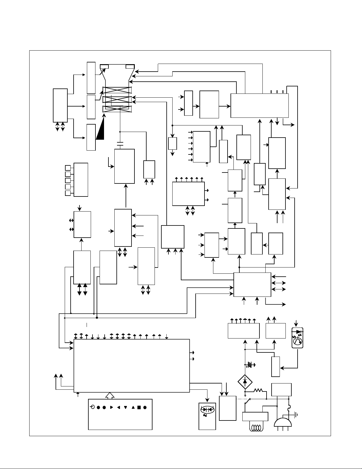
BLOCK DIAGRAM
- 13 -
5V
POWER OFF
STBY & SUS
8 BIT
MICOM
(IC271)
D-SUB
(SIGNAL CABLE)
EEPROM
(IC272)
VIDEO Pre Amp
CXA2153S
(IC302)
Video Amp
LM2412
(IC303)
CRT
R/G/B
CLAMP
CONTRA
ST
OSD SIGNAL
(R/G/B)
OSD PROCESSOR
(IC301)
12V
H-SYNC SIGNAL
V-SYNC SIGNAL.
Degaussing Coil
Degaussing
circuit
(RL901)
POWER
& DPM
LED
LINE
FILTER
(LF901)
PWM IC
(IC905)
SMPS
Main
(T951)
RECTIFIER
D901
7.5V
28V
15V
12V
-15V
80V
210V
H/V Sync
Processor
TDA4856
(IC201)
12V
H-out
2SC5597
(Q705)
SPCC &
H-size mixing
(IC2041)
H-LINRARITY
CORRECTION
(Q752,754,756,758
760,762)
High-voltage
PWM IC
M62501P
(IC501)
D/D CONVERTER
(Q405)
DYNAMIC
FOCUS VR
DYNAMIC
FOCUS VR
SCREEN VR
SCREEN
Dynamic Focus
High-voltage
V-out
TDA8177
(IC601)
CLAMP
CONTROL
TILT Control
(IC651)
Dynamic Focus
output
LF353
(IC291)
5V
H-SIZE
MUTE
5V
FLY
BACK
TRANS
(T501)
80V
R/G/B
R/G
BIAS
210V
15V
V-SAW
H-SYNC
V-SYNC
LED
DEG
STBY&SUS
Control panel
R
G
SMPS
Sub
(T901)
5V
6.3V
IIC-SDA
IIC-SCL
STC Control
(IC261)
IIC-SDA
IICC-SCL
DDC-SDA
DDC-SCL
EW
H-DRV
SDA
SCL
IIC-SDA
IICC-SCL
IIC
SIGNAL
X-RAY
H/V DETECT
FBT DRIVE
& SWITCHING
(Q515,516)
H-drive Trans
B+ CONTROL
(Q701,702,Q703)
D/D DRIVE
(IC402)
DF
H-CENTERING
COIL
210V
DUMY FBT
(T702)
195V
H-drive Trans
(T701)
F/V
DF B+
AFC
AFC
AFC
D/D CONVER
(Q525)
80V
D-FOUS AMP
15V
DF
15V
15V
X-RAY
15V
Power input
90~132Vac
180~264Vac ( 50/60Hz )
CS1
CS2
CS3
CS4
CS5
CS0
USB-DOWNUSB-UP
USB CONTROL
(IC501)
5-BNC
-15V
I/O EXPANDER
M62320
(IC791)
CS1
CS2
CS3
CS4
CS5
CS0
RL1
15V
RL2
IIC-SDA
IICC-SCL
RELAY
28V
4-CORNER PURITY
Control(IC611,631,651)
DAC
M62393
(IC691)
IIC-SDA
IICC-SCL
H-STC
V-STC
TILT
T/L
B/L
T/R
B/R
POWER
AUTO
ADJUST
ADJUST
ADJUST
ADJUST
MENU
SELECT
INPUT
H-SYNC
V-SYNC
RESET
SOG-IN
UNLOCK
IIC-SDA
IIC-SCL
DDC-SDA
DDC-SCL
LED
BNC/DSUB
KEY2
ST-IN
KEY1
H-Conv.
V-Conv
EBRT
UMUTE
SOG/SEP
Page 2

DESCRIPTION OF BLOCK DIAGRAM
- 14 -
1. Line Filter & Associated Circuit
This is used for suppressing noise of power input line
flowing into the monitor and/or some noise generated
in this monitor flowing out through the power input
line. That is to say, this circuit prevents interference
between the monitor and other electric appliances.
2. Degauss Circuit & Coil
The Degauss circuit consists of the degaussing coil,
the PTC (Positive Temperature Coefficient) thermistor
(TH901), and the relay(RL901). This circuit eliminates
abnormal color of the screen automatically by
degaussing the slot mask in the CRT when turn on the
power switch. When you need to degauss while using
the monitor select DEGAUSS in the SPECIAL on the
OSD menu.
3. SMPS(Switching Mode Power Supply).
This circuit works with power of 90~264Vac(50/60Hz).
The operation procedure is as follows:
1) AC input voltage is rectified and smoothed by the
bridge diode (D901) and capacitors (C905).
2) The rectified voltage (DC voltage) is applied to the
primary coil of the transformer (T901,T951)
3) The control IC (IC951) generates switching pulse to
turn on and off the primary coil of the transformer
(T951) repeatedly.
4) Depending on the turn ratio of the transformer , the
secondary voltages appear at the secondary coil of
the transformer (T951).
5) These secondary voltages are rectified by each
diode(D957,958,951,959,960,961,962) and operate
the other circuits. (Deflection , Video Amplifier ,.....
etc.)
The switching IC (IC951) controls input-pulse-width
and generates secondary voltages by sub-transformer
(T901)
4. Display Power Management Circuit.
This circuit control power consumption of the monitor
by detecting H and V sync signal.
There are Stand-by and suspend mode.
When no horizontal or vertical sync signal input, the
circuit consists of IC903 becomes stand-by and
suspend mode. Its power consumption is below 8W.
5. X-ray Protection.
This circuit detects the rectified DC voltage comes
from the FBT pin 6. If the high volltage of the FBT
reaches up to about 30kV (abnormal state) , high
voltage control PWM IC (IC501) detects it. And PWM
IC (IC501) prevent output voltage to the gate of
switching FET(Q525).It stops operating primary circuit
of the FBT (T501), and high voltage is not be
generated.(In the normal state, the high voltage is
about 27kV.)
6. Micom (Microprocessor) Circuit.
The operating procedure of Micom (Microprocessor)
and its associated circuit is as follows:
1) H and V Sync signal is supplied from the D-sub to the
Micom (IC271).
2) The Micom (IC271) distinguishes polarity and
frequency of H and V sync.
3) The Micom controls each OSD function signals.(Hsize, H-position, V-size, etc.)
4) The controlled data of each mode is stored in itself.
User can adjust screen condition by each OSD
function. The data of the adjust screen condition is
stored automatically.
7. Horizontal and Vertical Synchronous Processor
This circuit generates the horizontal drive pulse and
the vertical drive pulse by taking sync-signal form the
D-SUB (P208). This circuit consists of the TDA4856
(IC201) and the associated circuit.
8. Oscillating Circuit for D/D Converter.
This circuit generates the saw-tooth wave which has
the horizontal period by taking the output of the
TDA4856 (IC201).
9. D/D (DC to DC) Converter.
This circuit supplies DC voltage to the horizontal
deflection output circuit by decreasing DC 210V
which is the secondary voltage of the SMPS in
accordance with the input horizontal sync signal.
10. Side-Pincushion Correcting Circuit.
This circuit improves the side-pincushion of the screen
by mixing east-west wave to the output of the
horizontal deflection D/D converter which is used for
the supply voltage source (B+) of the deflection
circuit.
11. D/D Drive & Convert Circuit.
This circuit is used for supplying B+ voltage to
horizontal deflection output transistor(Q705). This
circuit makes to add side-pincushion correcting signal
to B+ voltage.
12. Horizontal Deflection Output Circuit.
This circuit makes the horizontal deflection by
supplying the saw-tooth current to the horizontal
deflection yoke.
13. High Voltage Output & FBT (Fly Back Transformer).
The high voltage output circuit is used for generating
pulse wave to the primary coil of the FBT (Fly Back
Transformer (T501)). A boosted voltage (about 27kV)
appears at the secondary of the FBT and it is supplied
to the anode of the CRT. And there are another output
voltages such as the dynamic focus frequency.
Page 3

- 15 -
14. H-Linearity Correction Circuit.
This circuit corrects the horizontal linearity for each
horizontal sync frequency.
15. Vertical Output Circuit.
This circuit takes the vertical ramp wave form the
TDA4856(IC201) and performs the vertical deflection
by supplying the saw-tooth wave current form the
TDA8177 (IC601) to the vertical deflection yoke.
16. Dynamic Focus Output circuit.
This circuit takes H and V parabola wave from the
TDA4856(IC201) and amplifies these waves to offer to
the FBT(T501).
17. H & V Blanking and Brightness Control.
This circuit eliminates the retrace line by supplying a
negative pulse to the G1 of the CRT. The brightness
control circuit is used to control of the screen
brightness by changing the DC level of G1.
18. Tilt (Image Rotation) Circuit.
This circuit corrects the tilt of the screen by supplying
the image rotation signal to the tilt coil which is
attached to the CRT near the deflection.
19. Static Convergence Control Circuit.
This circuit corrects the convergence of the screen by
supplying the convergence signal to the 4H(STC) coil
which is attached to the CRT near the deflection.
20. Moiré Reduction Circuit.
This circuit reduce interference between the periodical
display pattern and the CRT’s slot (or dot). The
positions of every other one dot video signal beams
(red, green and blue beam) are shifted finely, thus
reducing interference.
21. OSD Circuit.
This circuit is used for performing the OSD (On
Screen Display) function. When a user selects the
OSD Select/ Adjustment control, the adjustment status
displays on the screen.
22. Video Pre-Amp Circuit.
This circuit amplifies the analog video signal from 0-
0.7V to 0-4V. This circuit is operated by taking the
clamp, R, G, B drives, and contrast signals from the
Micom (IC271).
23. Video Output Amp Circuit.
This circuit amplifies the video signal which comes
from the video pre-amp circuit and amplified video
signal is applied to the CRT cathode.
 Loading...