

LG MT-60PZ90V-M, MT-60PZ92M-V, MZ-60PZ92V Schematic

PLASMA MONITOR
SERVICE MANUAL
CAUTION
BEFORE SERVICING THE CHASSIS,
READ THE SAFETY PRECAUTIONS IN THIS MANUAL.
CHASSIS : RF-03LA
MODEL : MT-60PZ90V/M/92M/V
MODEL : MZ-60PZ92V
website:http://biz.LGservice.com
e-mail:http://www.LGEservice.com/techsup.html
INPUT
SELECT
VOLUME
ON/OFF

- 2 -
CONTENTS
SAFETY PRECAUTIONS ...................................................................................3
DESCRIPTION OF CONTROLS ........................................................................ 4
SPECIFICATIONS .............................................................................................. 8
ADJUSTMENT INSTRUCTIONS ........................................................................9
PRINTED CIRCUIT BOARD ..............................................................................12
BLOCK DIAGRAM.............................................................................................21
EXPLODED VIEW..............................................................................................22
EXPLODED VIEW PARTS LIST........................................................................23
REPLACEMENT PARTS LIST...........................................................................24
SCHEMATIC DIAGRAM ........................................................................................

- 3 -
SAFETY PRECAUTIONS
Many electrical and mechanical parts in this chassis have special safety-related characteristics. These parts are identified by in
the Schematic Diagram and Replacement Parts List.
It is essential that these special safety parts should be replaced with the same components as recommended in this manual to
prevent X-RADIATION, Shock, Fire, or other Hazards.
Do not modify the original design without permission of manufacturer.
General Guidance
An isolation Transformer should always be used during
the servicing of a receiver whose chassis is not isolated from
the AC power line. Use a transformer of adequate power rating
as this protects the technician from accidents resulting in
personal injury from electrical shocks.
It will also protect the receiver and it's components from being
damaged by accidental shorts of the circuitry that may be
inadvertently introduced during the service operation.
If any fuse (or Fusible Resistor) in this monitor is blown, replace
it with the specified.
When replacing a high wattage resistor (Oxide Metal Film
Resistor, over 1W), keep the resistor 10mm away from PCB.
Keep wires away from high voltage or high temperature parts.
Due to high vacuum and large surface area of picture tube,
extreme care should be used in handling the Picture Tube.
Do not lift the Picture tube by it's Neck.
Leakage Current Cold Check(Antenna Cold Check)
With the instrument AC plug removed from AC source,
connect an electrical jumper across the two AC plug prongs.
Place the AC switch in the on position, connect one lead of
ohm-meter to the AC plug prongs tied together and touch other
ohm-meter lead in turn to each exposed metallic parts such as
antenna terminals, phone jacks, etc.
If the exposed metallic part has a return path to the chassis, the
measured resistance should be between 1MΩ and 5.2MΩ.
When the exposed metal has no return path to the chassis the
reading must be infinite.
An other abnormality exists that must be corrected before the
receiver is returned to the customer.
Leakage Current Hot Check (See below Figure)
Plug the AC cord directly into the AC outlet.
Do not use a line Isolation Transformer during this check.
Connect 1.5K/10watt resistor in parallel with a 0.15uF capacitor
between a known good earth ground (Water Pipe, Conduit, etc.)
and the exposed metallic parts.
Measure the AC voltage across the resistor using AC
voltmeter with 1000 ohms/volt or more sensitivity.
Reverse plug the AC cord into the AC outlet and repeat AC
voltage measurements for each exposed metallic part. Any
voltage measured must not exceed 0.75 volt RMS which is
corresponds to 0.5mA.
In case any measurement is out of the limits specified, there is
possibility of shock hazard and the set must be checked and
repaired before it is returned to the customer.
Leakage Current Hot Check circuit
1.5 Kohm/10W
To Instrument's
exposed
METALLIC PARTS
Good Earth Ground
such as WATER PIPE,
CONDUIT etc.
AC Volt-meter
IMPORTANT SAFETY NOTICE
0.15uF
- 4 -
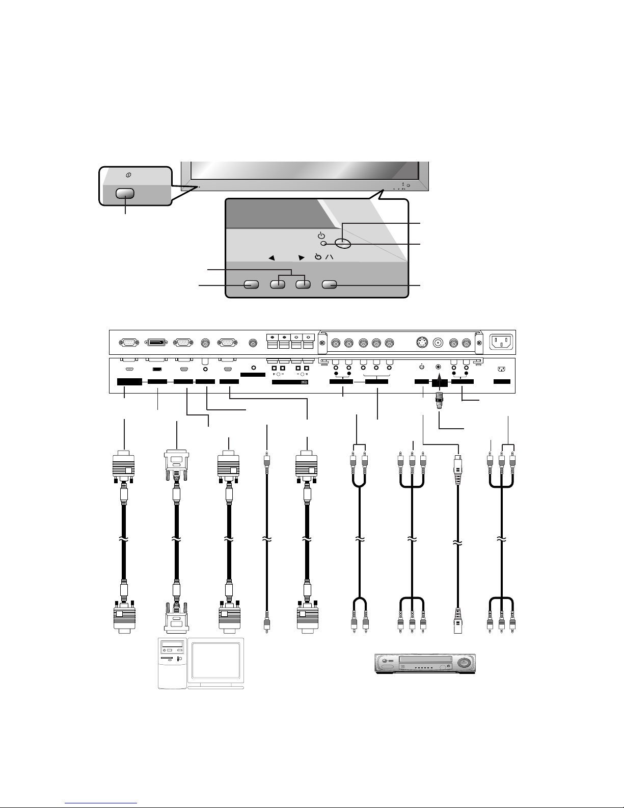
DESCRIPTION OF CONTROLS
<Back Panel>
<Front Panel Controls>
Connection to PC
Note: The connection cables shown above to the right are not included with the Monitor.
A D-sub 15-pin cable and a DVI cable are provided to connect the Monitor to a PC.
Connection to AV equipment
( )( )
R
( )( )
L
EXTERNAL SPEAKER
YPBP
R
(MONO)
R
AUDIO
L
R
AUDIO
L
S-VIDEO AC INPUTAUDIO INPUT
AUDIO INPUT
COMPONENT INPUT
REMOTE CONTROL
RS-232C INPUT
(CONTROL/SERVICE)
AUDIO INPUT RGB OUTPUTRGB INPUTDVI INPUT
VIDEO
INPUT
INPUT
SELECT
VOLUME
ON/OFF
ON/OFF
INPUT
SELECT
VOLUME
Main Power Button
INPUT SELECT Button
VOLUME (
F,G
) Buttons
Power Standby Indicator
Illuminates red in standby mode,
Illuminates green when the
Monitor is turned on
Remote Control Sensor
Sub power button
AUDIO
INPUT
VIDEO
INPUT
S-VIDEO
INPUT
AUDIO
INPUT
RS-232C
INPUT
DVI INPUT
RGB INPUT
RGB
OUTPUT
AUDIO
INPUT
COMPO-
NENT INPUT
- Shown is a simplified representation of the Monitor.
- Here shown may be somewhat different from your set.

- 5 -
1. RS-232C INPUT(CONTROL/SERVICE) PORT
Connect to the RS-232C port on a PC.
2. DVI INPUT / RGB INPUT / AUDIO INPUT SOCKETS
Connect the monitor output socket of the PERSONAL
COMPUTER to this socket.
RGB OUTPUT SOCKET
You can watch the RGB signal on another monitor, connect RGB OUTPUT to another monitor’s PC input port.
3. REMOTE CONTROL
Connect your wired remote control to the Remote port on
the Monitor.
4. EXTERNAL SPEAKER OUTPUT (8 ohm)
Connect to optional external speaker(s).
* For further information, refer to ‘Speaker & Speaker
Stand’ manual.
5. AUDIO / COMPONENT INPUT / S-VIDEO / VIDEO INPUT
/ AUDIO INPUT SOCKETS
EURO SCART SOCKET
Note : The interface board (AP-60EA30/31) is not
equipped on MT/MZ-60PZ90/92 series models. Contact
your dealer for buying this optional item.
6. POWER CORD SOCKET
This Monitor operates on an AC power. The voltage is
indicated on the Specifications page. Never attempt to
operate the Monitor on DC power.
AV1AV1
( )
( )
R
( )
( )
L
EXTERNAL SPEAKER
AC INPUT
RS-232C INPUT
(CONTROL/SERVICE)
AUDIO INPUT RGB OUTPUTRGB INPUTDVI INPUT
REMOTE CONTROL
<Back Panel>
RCA Type
Scart Type
5
( )( )
R
( )( )
L
EXTERNAL SPEAKER
Y PBP
R
(MONO)
R
AUDIO
L
R
AUDIO
L
S-VIDEO AC INPUTAUDIO INPUT
AUDIO INPUT
COMPONENT INPUT
REMOTE CONTROL
RS-232C INPUT
(CONTROL/SERVICE)
AUDIO INPUT RGB OUTPUTRGB INPUTDVI INPUT
VIDEO
INPUT
41 2 63 5
- 6 -
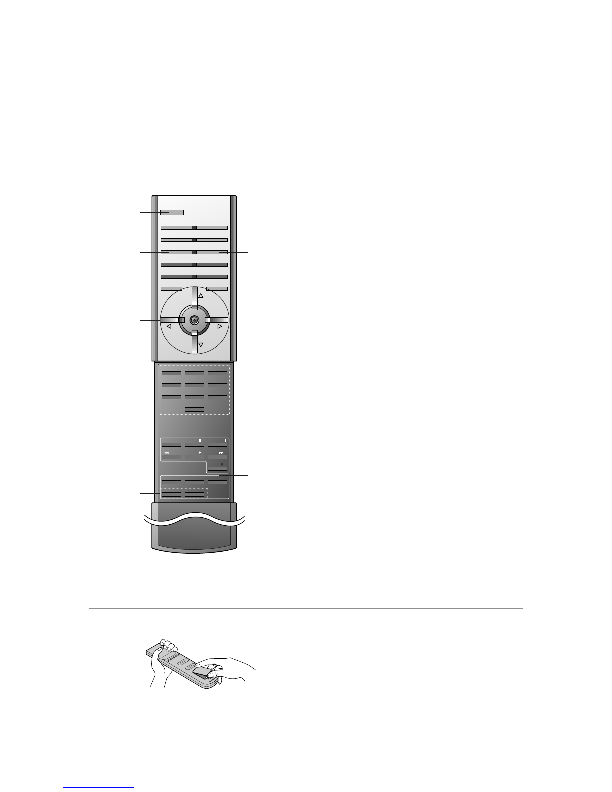
- When using the remote control aim it at the remote control sensor of the Monitor.
- There’s maybe defect in consecutive operation of remote control in specified brightness according to this monitor feature.
1 2 3
4 5 6
7 8
0
9
POWER
SLEEP INPUT SELECT
PSM SSM
ARC PIP ARC
PIP
TWIN PICTURE
SWAP
MENU MUTE
OK
VOL
POWER STOP
PLAY FF
REC
REW
P/STILL
WIN.SIZE
WIN.POSITION
ZOOM +
ZOOM -
SPLIT ZOOM
VOL
SUB INPUT
1. POWER
switches the set on from standby or off to standby.
2. SLEEP
sets the sleep timer.
3. PSM (Picture Status Memory)
recalls your preferred picture setting.
4. ARC (Aspect Ratio Control)
changes the picture format.
5. PIP
switches the sub picture on or off.
6. SWAP
alternates between main and sub picture.
7. MENU Button
selects a menu.
8.
DD/ EE
selects a menu item.
FF/ GG
(Volume Down/Up)
adjusts the volume.
adjusts menu settings.
OK
displays the current mode.
9. NUMBER BUTTONS
10. VCR BUTTONS
control a LG video cassette recorder.
11. WIN. SIZE
adjusts the sub picture size.
12. ZOOM-/ZOOM+
13. INPUT SELECT BUTTON
selects TV, AV or PC monitor mode.
14. SSM (Sound Status Memory)
recalls your preferred sound setting.
15. PIP ARC
changes the picture format of PIP.
16. TWIN PICTURE
17. SUB INPUT
selects the input mode for the sub picture.
18. MUTE Button
switches the sound on or off.
19. SPLIT ZOOM
enlarge the screen with regular ration.
20. WIN.POSITION
moves the sub picture to
DD/ EE
or FF/ GGdirection.
1
13
14
15
16
17
18
19
20
2
3
4
5
6
7
8
9
10
11
12
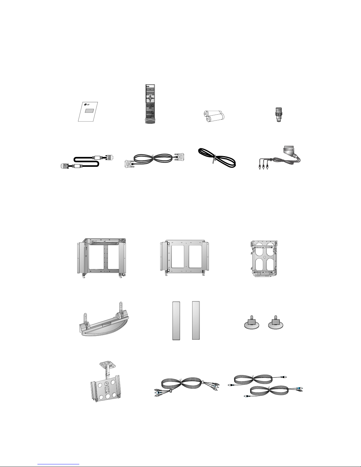
• Open the battery compartment cover on the back side and
insert the batteries with correct polarity.
• Apply two 1.5V alkaline batteries of AAAtype. Don’t mix the
used batteries with new batteries.
• Install the batteries with the correct polarities.
Installing Batteries
- 7 -
D-sub 15 pin cable
AS mark
LG TV
Owner’s Manual
1.5V
1.5V
Alkaline batteries
BNC-RCA adapter (optional)
DVI cable
Power cord
1 2 3
4 5 6
7 809
POWER
SLEEP INPUT SELECT
PSM SSM
ARC PIP ARC
PIP
TWIN PICTURE
SWAP
MENU MUTE
OK
VOL
POWER STOP
PLAY FF
REC
REW
P/STILL
WIN.SIZE
WIN.POSITION
ZOOM +
ZOOM -
SPLIT ZOOM
VOL
SUB INPUT
Remote control handset
Phone scart cable (Optional)
Ceiling mounting bracket
- Optional extras can be changed or modified for quality improvement without any notification new optional extras can be
added.
- Contract your dealer for buying these items.
Accessories
Optional Extras
Tilt wall mounting bracket
Wall mounting bracket
Desktop stand
Video cables
Desktop Speaker stand
Speakers
PC audio cables
Vertical Wall mounting bracket

- 8 -
SPECIFICATIONS
NOTE : Specifications and others are subject to change without notice for improvement
.
V Scope
This specification can be applied to all model of 60”PDP MONITOR related to RF-03LA Chassis.
V Test Condition
1) Temperature : 25¡ 5°C
2) Relative Humidity: 65¡ 10%
3) Power Voltage:Standard Input Voltage
(AC 110V-240V~, 50/60Hz)
But Standard input voltage of each product is marked by model.
4) Specification and performance of each parts are followed each drawing and specification by part number in accordance with BOM.
5)
The receiver must be operated for about 20 minutes prior to the adjustment
.
V Test and Inspection Method
1) Performance : Follow the Standard of LG TV test
2) Demanded other specification
Safety: UL, CSA, IEC specification
EMC : Fcc, ICES, IEC specification
Remark
Safety: IEC60065,IEC60095
EMI : EN55013
-Conducted / Radiation
Safety : IEC60065,IEC60095
EMI : EN55013
-Conducted / Radiation
Model Name
MZ-60PZ92V
MT-60PZ90V
Market
EU
N-EU
Chassis
RF-03LA
Brand
LG
Model Name
MZ-60PZ92V
MT-60PZ90V
Market Place
EU
N-EU
1. Application Object
These instructions are applied to all of the PDP MONITOR,
RF-03FA chassis.
2. Notes
(1) Because this is not a hot chassis, it is not necessary to use
an isolation transformer. However, the use of isolation
transformer will help protect test instrument.
(2) Adjustment must be done in the correct order.
(3) The adjustment must be performed in the circumstance of
25±5°C of temperature and 65±10% of relative humidity if
there is no specific designation.
(4) The input voltage of the receiver must keep 220V, 60Hz in
adjusting.
(5) The receiver must be operated for about 15 minutes prior
to the adjustment.
¤ After RGB Full white HEAT-RUN Mode, the receiver
must be operated prior to adjustment.
¤ŁEnter into HEAT-RUN mode
- Press the POWER ON Key on Remote Control for
adjustment.
- Press the VOL + Key. HEAT RUN WHITE OSD
display and screen display 100% full WHITE
PATTERN.
[ Set is activated HEAT-RUN without signal generator in
this mode.
[ Single color pattern(RED/BLUE/GREEN) of HEAT-RUN
mode uses to check PANEL.
Caution)
If you turn on a still screen more than 20 minutes, a
after image may be occur in the black level part of
the screen.
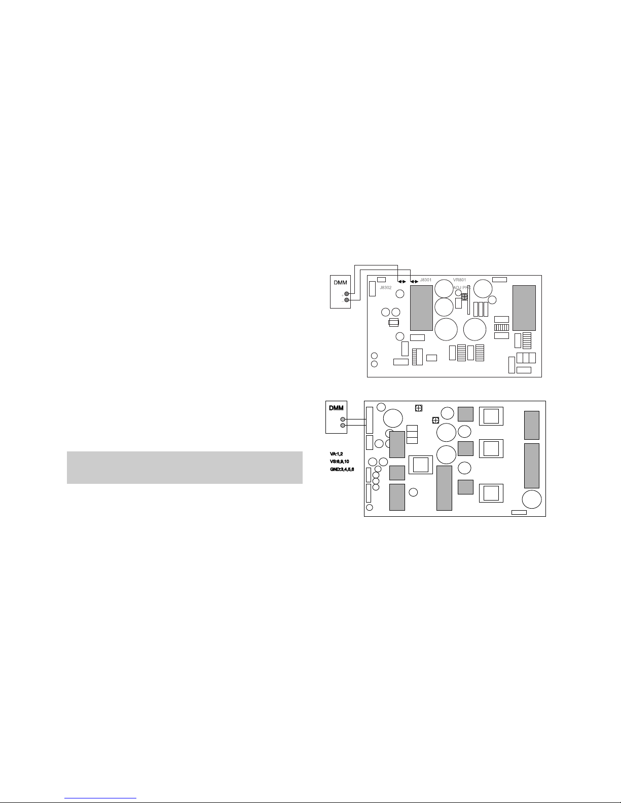
3. POWER PCB Assy Voltage
Adjustment (Va, Vs, Voltage Adjustment)
3-1. Test Equipment
: D.M.M 1EA
3-2. Connection Diagram for Measuring
: refer to fig.1
3-3. Adjustment Method
(1) PFC adjustment
¤ After receiving 100% Full White Pattern(06CH), HEAT
RUN.
¤Ł Connect +terminal of D.M.M to TP1 PFC+(J8302),
connect -terminal to TP2 PFC-(J8301)
¤Ø After turning VR 801, voltage of D.M.M adjust 380V
(deviation; ±1V)
(2) Va Adjustment
¤ After receiving 100% Full White Pattern, HEAT RUN.
¤ŁConnect + terminal of D.M.M to Va pin of P805 and
connect – terminal to GND pin of P805.
¤ØAfter turning the VR8401, voltage of D.M.M adjustment
as same as Va voltage which on label of panel
Right/Top. (Deviation : ±0.5V)
(3) Vs Adjustment
¤ Connect + terminal of D.M.M to Vs pin of P805 and
connect – terminal to GND pin of P805.
¤Ł After turning the VR8501, voltage of D.M.M adjustment
as same as Vs voltage which on label of panel
Right/Top. (Deviation : ±0.5V)
4. RGB Auto Cut-Off & MIN Bias
MAX Bias adjustment
(1) Input Full White (255 Gray) signal which generated from
Pattern Generator into RGB.
(2) Press POWER ON KEY on R/C for adjustment and select
Auto Cut-Off.
(3) Press Vol. + key and operate TO SET
(4) Original Window screen will be presented about 3-5
seconds later. And if there is a mark of OK OSD, then
Auto Cut-off will be completed.
(5) After adjustment, Press (
A)ENTER Key to save
adjustment mode.
O Data value, which adjusted in the board, is valid until the VSC
Board is dissuaded and must be protected.
- 9 -
ADJUSTMENT INSTRUCTIONS
Each PCB Assy must be checked by the Check JIG Set before
whole assembly. (Be careful the POWER PCB Assy not to
damage to PDP Module)
<Fig.1> Connection Diagram of Power Adjusment for Measuring
VR8501VR8501
VS VS ADJADJ
VR8401VR8401
VVAA ADJADJ
<Fig.2> Connection Diagram of Vs, Va Power adjusment for measuring
O For the protection of data, Micom does not permit any more
adjustment is completed well.
O In case of re-adjustment, operate First Value Setting.
1) Press both Volume +key of local key instart key of R/C for
adjustment.
2) Few second later, Temperture OSD display, then Press
onstop key of R/C for adjustment.
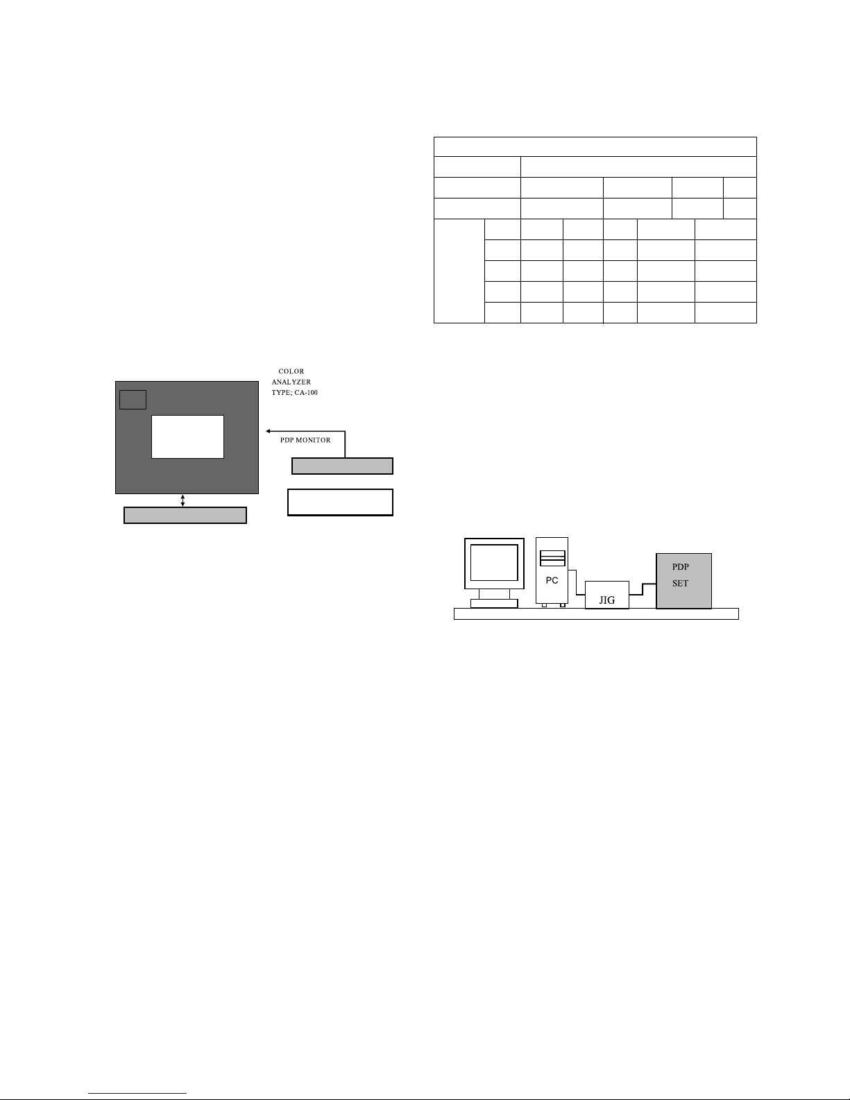
5. Adjustment of White Balance
5-1. Required Equipment
Color analyzer (CA-100 or same product)
5-2. Connection Diagram of Equipment for
Measuring (Auto Adjustment)
5-3. Adjustment of White Balance(Manual
adjustment)
O Operate the Zero-calibration of the CA-100, then stick
sensor to PDP module surface when you adjust..
O For manual adjustment, it is also possible by the following
sequence.
(1) Select WHITE PATTERN of HEAT RUN mode by pressing
POWER ON KEY on R/C for adjustment then operate
HEAT RUN more than 15 minute.
(2) Supply 216Gray Level, 50% size length and breadth signal
to RGB input.
(3) To adjust High Light, stick sensor to 216Gray Level(or
105~115 Cd/m2) Pattern, press ADJ Key on R/C for
adjustment and press
D, E on R/C in adjustment mode to
select R-H or G-H, press VOL +, - Key and adjust it until
color coordination becomes as below.
X: 0.280±0.003, Y: 0.290±0.003
Color temperature: 10,000°K±500°K
(4) Exit adjustment mode using V Key.
5-4. Auto adjustment (RS-232C)
6. DDC Data Input
6-1. Required Test Equipment
(1) A jig for adjusting PC, DDC. (PC serial to D-sub.
Connection equipment)
(2) S/W for writing DDC(EDID data write & read)
(3) D-Sub 15P cable, D-Sub to DVI Connector (Connect to
DVI Jack)
6-2. Setting of Device
6-3. Preparation for Adjustment
(1) Set devices as above and turn the PC, jig on.
(2) Put S/W for writing DDC (EDID data write & read) into
operation. (operated in DOS mode.)
6-4. Sequence of Adjustment
(1) DDC Data Input for Analog-RGB
¤ Put the set on the table and turn the power on.
¤ŁConnect PC Serial to D-sub 15P Cable of JIG for DDC
adjustment to RGB terminal (D-Sub 15Pin).
¤Ø Operate S/W for DDC record and select DDC Data for
Analog RGB in Model Menu.
¤Œ Operate EDID Write command.
¤º Operate EDID Read command and check whether
Check Sum is OK.
¤ If Check Sum is NG, repeat ¤Ø~ ¤Œ.
¤ If Check Sum is OK, DDC Data for Analog-RGB input is
completed.
(2) DDC Data input for Digital-RGB(DVI)
¤ Connect PC Serial to DVI Cable of JIG for DDC
adjustment to DVI terminal (DVI Jack).
- 10 -
R - H216R - H216
G - H216 G - H216
B - H216 B - H216
Window
MSPG-2100 or
MSTG-5200
RGB Signal Input
High Light adjustment
216 Gray Level
105 ~ 115 Cd/m
2
RS-232C communication
<Fig.3> Connection Diagram of Manual Adjustment
Type
Baud Rate
1150200
Index
R-H
G-H
Data bit
8
Cmd1 Cmd2
j a
j b
Stop bit1Parity
NONE
RF-03LA
Protocol
Setting
Data Min Value
180(B4)
170(A4)
Max Value
254(FE)
250(FA)
RS232

¤ŁOperate S/W for DDC record and select DDC Data for
Digital RGB in Model Menu.
¤ØOperate EDID Write command.
¤Œ Operate EDID Read command and check whether
Check Sum is OK.
¤ºIf Check Sum is NG, repeat ¤Ø~ ¤Œ.
¤ If Check Sum is OK, DDC Data for Digital-RGB input is
completed.
7. Adjustment of Component Off-Set
7-1. Required Test Equipment
: HD-STB(SK-011T) or same product
7-2. Manual Adjustment of Component Off-
Set
(1) Input Video signal and Component 720P signal of HD-
STB.
(2) Press ADJ key of R/C twice for entering twin picture mode.
(3) Adjust the same color senses between main and sub,
using Volume +; -key of R/C in R, G, B Off-Set menu.
- 11 -
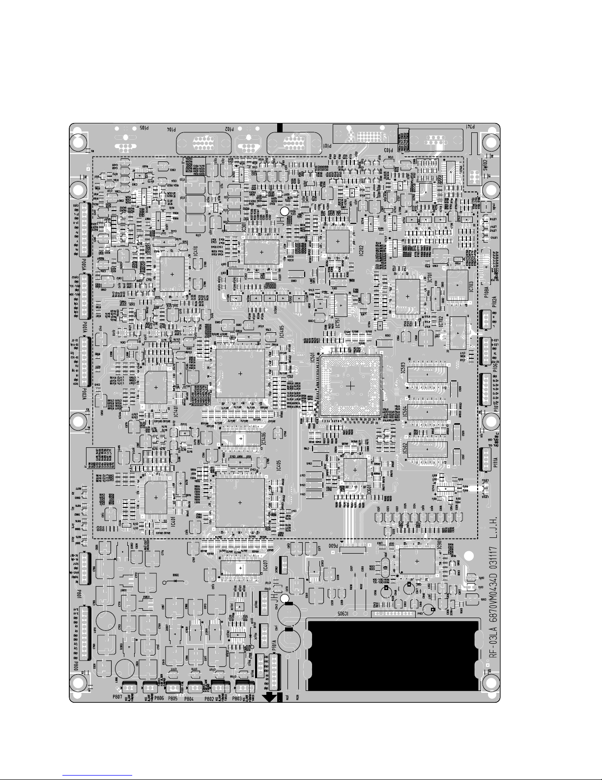
- 12 -
MAIN (TOP)
PRINTED CIRCUIT BOARD
 Loading...