

LG MT-50PZ41, MT-50PZ43S, MZ-50PZ42, MZ-50PZ43 User Manual

Please read this manual carefully before operating your set.
Retain it for future reference.
Record model number and serial number of the set.
See the label attached on the back cover and quote this information to your dealer when you require service.
Model number :
Serial number :
PLASMA MONITOR
OWNER’S MANUAL
MT-50PZ40/H/A/B/K/R/S
MT-50PZ41/H/A/B/K/R/S
MT-50PZ43/H/A/B/K/R/S
MZ-50PZ42/H/A/B/K/R/S
MZ-50PZ43/H/A/B/K/R/S
P/NO : 3828VA0351A (RF02CA, 067Y TX, 373-026H) f
2
What is a Plasma Display ?
If voltage is inputted to gas in glass panels, ultraviolet rays is outputted and fused with a fluorescent substance. At this
moment, light is emitted. APlasma Display is a next generation flat Display using this phenomenon.
160° - Wide angle range of vision
A Plasma Display provides more than 160° angle range of vision so that you can get a picture without distortion from
any direction.
Easy installation
A Plasma Display is much lighter and smaller than other same class products so that you can install the Plasma Display
at the desired place.
Big screen
The screen of a Plasma Display is 50" so that you can get vivid experience as if you are in a theater.
Multimedia Plasma Display
A Plasma Display can be connected with a computer so that you can use it as a screen for conference, game, internet
and so on.
The explanation about coloured dots may be present on PDP screen
The PDP which is the display device of this product is composed of 0.9 to 2.2 million cells and a few cell defects can
occur in the manufacture of the PDP. Several coloured dots visible on the screen would be acceptable, in line with other
PDP manufacturers and would not mean that the PDP is faulty. We hope you will understand that the product which corresponds to this standard is regarded as acceptable. It means that it could not be changed or refunded.
We promise that we'll do our best to develop our technology to minimize the cell defects.
WARNING
MT-50PZ40 / MZ-50PZ42 series : This is Class B product. In a domestic environment this product may
cause radio interference in which case the user may be required to take adequate measures.
WARNING
This is Class Aproduct. In a domestic environment this product may cause radio interference in which
case the user may be required to take adequate measures.
WARNING
TO REDUCE THE RISK OF FIRE AND ELECTRIC SHOCK, DO NOT EXPOSE THIS PRODUCT TO
RAIN OR MOISTURE.
LG Plasma Monitor
LG Plasma Monitor

After reading this manual, keep it in the place
where the user can
always contact easily.
Safety Instructions . . . . . . . . . . . . . . . . . . . . . . . . . . . . . . . . . . . . . . . . . . . . . . . .4
Equipment Connections and Setup
Controls of the Monitor . . . . . . . . . . . . . . . . . . . . . . . . . . . . . . . . . . . . . . . . . . . . .6
Watching External Equipments . . . . . . . . . . . . . . . . . . . . . . . . . . . . . . . . . . . . . . .7
Displayable Monitor Specification . . . . . . . . . . . . . . . . . . . . . . . . . . . . . . . . . . . .10
Controls of the Remote control . . . . . . . . . . . . . . . . . . . . . . . . . . . . . . . . . . . . . .11
Installation of the Simple monitor stand . . . . . . . . . . . . . . . . . . . . . . . . . . . . . . . .13
Monitor installation . . . . . . . . . . . . . . . . . . . . . . . . . . . . . . . . . . . . . . . . . . . . . . .13
Basic Features Setup and Operation
Turning on the Monitor . . . . . . . . . . . . . . . . . . . . . . . . . . . . . . . . . . . . . . . . . . . .14
Menu language setup . . . . . . . . . . . . . . . . . . . . . . . . . . . . . . . . . . . . . . . . . . . . .14
VIDEO Menu
PSM(Picture Status Memory) . . . . . . . . . . . . . . . . . . . . . . . . . . . . . . . . . . . . . . .15
Adjusting Auto Colour Control . . . . . . . . . . . . . . . . . . . . . . . . . . . . . . . . . . . . . . .15
Manual Colour Temperature Control . . . . . . . . . . . . . . . . . . . . . . . . . . . . . . . . . .15
Manual picture Control . . . . . . . . . . . . . . . . . . . . . . . . . . . . . . . . . . . . . . . . . . . .15
AUDIO Menu
SSM(Sound Status Memory) . . . . . . . . . . . . . . . . . . . . . . . . . . . . . . . . . . . . . . . .16
AVL(Auto Volume Leveler) . . . . . . . . . . . . . . . . . . . . . . . . . . . . . . . . . . . . . . . . .16
Adjusting Sound . . . . . . . . . . . . . . . . . . . . . . . . . . . . . . . . . . . . . . . . . . . . . . . . .16
TIME Menu
Setting the Clock . . . . . . . . . . . . . . . . . . . . . . . . . . . . . . . . . . . . . . . . . . . . . . . .17
Setting the On/Off Timer . . . . . . . . . . . . . . . . . . . . . . . . . . . . . . . . . . . . . . . . . . .17
Auto Off . . . . . . . . . . . . . . . . . . . . . . . . . . . . . . . . . . . . . . . . . . . . . . . . . . . . . . .17
Sleep Timer . . . . . . . . . . . . . . . . . . . . . . . . . . . . . . . . . . . . . . . . . . . . . . . . . . . .17
SPECIAL Menu
Child lock . . . . . . . . . . . . . . . . . . . . . . . . . . . . . . . . . . . . . . . . . . . . . . . . . . . . . .18
Orbiter . . . . . . . . . . . . . . . . . . . . . . . . . . . . . . . . . . . . . . . . . . . . . . . . . . . . . . . .18
White Wash . . . . . . . . . . . . . . . . . . . . . . . . . . . . . . . . . . . . . . . . . . . . . . . . . . . .18
SCREEN Menu
Auto adjustment . . . . . . . . . . . . . . . . . . . . . . . . . . . . . . . . . . . . . . . . . . . . . . . . . 19
Setting Picture Format . . . . . . . . . . . . . . . . . . . . . . . . . . . . . . . . . . . . . . . . . . . .19
Split Zoom . . . . . . . . . . . . . . . . . . . . . . . . . . . . . . . . . . . . . . . . . . . . . . . . . . . . .19
Screen Position . . . . . . . . . . . . . . . . . . . . . . . . . . . . . . . . . . . . . . . . . . . . . . . . .20
Manual Configure . . . . . . . . . . . . . . . . . . . . . . . . . . . . . . . . . . . . . . . . . . . . . . . .20
Screen Adjustments . . . . . . . . . . . . . . . . . . . . . . . . . . . . . . . . . . . . . . . . . . . . . .20
Initializing (Reset to factory value) . . . . . . . . . . . . . . . . . . . . . . . . . . . . . . . . . . . .20
PIP Function
Watching PIP . . . . . . . . . . . . . . . . . . . . . . . . . . . . . . . . . . . . . . . . . . . . . . . . . . . 21
PIP Aspect Ratio . . . . . . . . . . . . . . . . . . . . . . . . . . . . . . . . . . . . . . . . . . . . . . . . .21
Moving the PIP . . . . . . . . . . . . . . . . . . . . . . . . . . . . . . . . . . . . . . . . . . . . . . . . . .21
Main Picture Size Adjustment . . . . . . . . . . . . . . . . . . . . . . . . . . . . . . . . . . . . . . .21
PIP Size . . . . . . . . . . . . . . . . . . . . . . . . . . . . . . . . . . . . . . . . . . . . . . . . . . . . . . .21
Swapping the PIP . . . . . . . . . . . . . . . . . . . . . . . . . . . . . . . . . . . . . . . . . . . . . . . .21
Selecting a source input signal for the PIP . . . . . . . . . . . . . . . . . . . . . . . . . . . . .21
Main Picture Position Adjustment . . . . . . . . . . . . . . . . . . . . . . . . . . . . . . . . . . . .21
TWIN Picture
Main Picture Size Adjustment . . . . . . . . . . . . . . . . . . . . . . . . . . . . . . . . . . . . . . .22
Sub Picture Size Adjustment . . . . . . . . . . . . . . . . . . . . . . . . . . . . . . . . . . . . . . . .22
Selecting a source for the Twin Picture . . . . . . . . . . . . . . . . . . . . . . . . . . . . . . . .22
Swapping the Twin Picture . . . . . . . . . . . . . . . . . . . . . . . . . . . . . . . . . . . . . . . . . 22
External Control Device Setup . . . . . . . . . . . . . . . . . . . . . . . . . . . . . . . . . . . . .23
Others
Troubleshooting check list . . . . . . . . . . . . . . . . . . . . . . . . . . . . . . . . . . . . . . . . . .30
Product specifications . . . . . . . . . . . . . . . . . . . . . . . . . . . . . . . . . . . . . . . . . . . . .31
Contents
3
4
Safety Instructions
Do not place the Monitor in direct sunlight or near heat
sources such as heat registers, stove and so on.
- This may cause a fire.
Do not use the Monitor in damp place such as a bathroom or any place where it is likely to get wet.
- This may cause a fire or could give an electric shock.
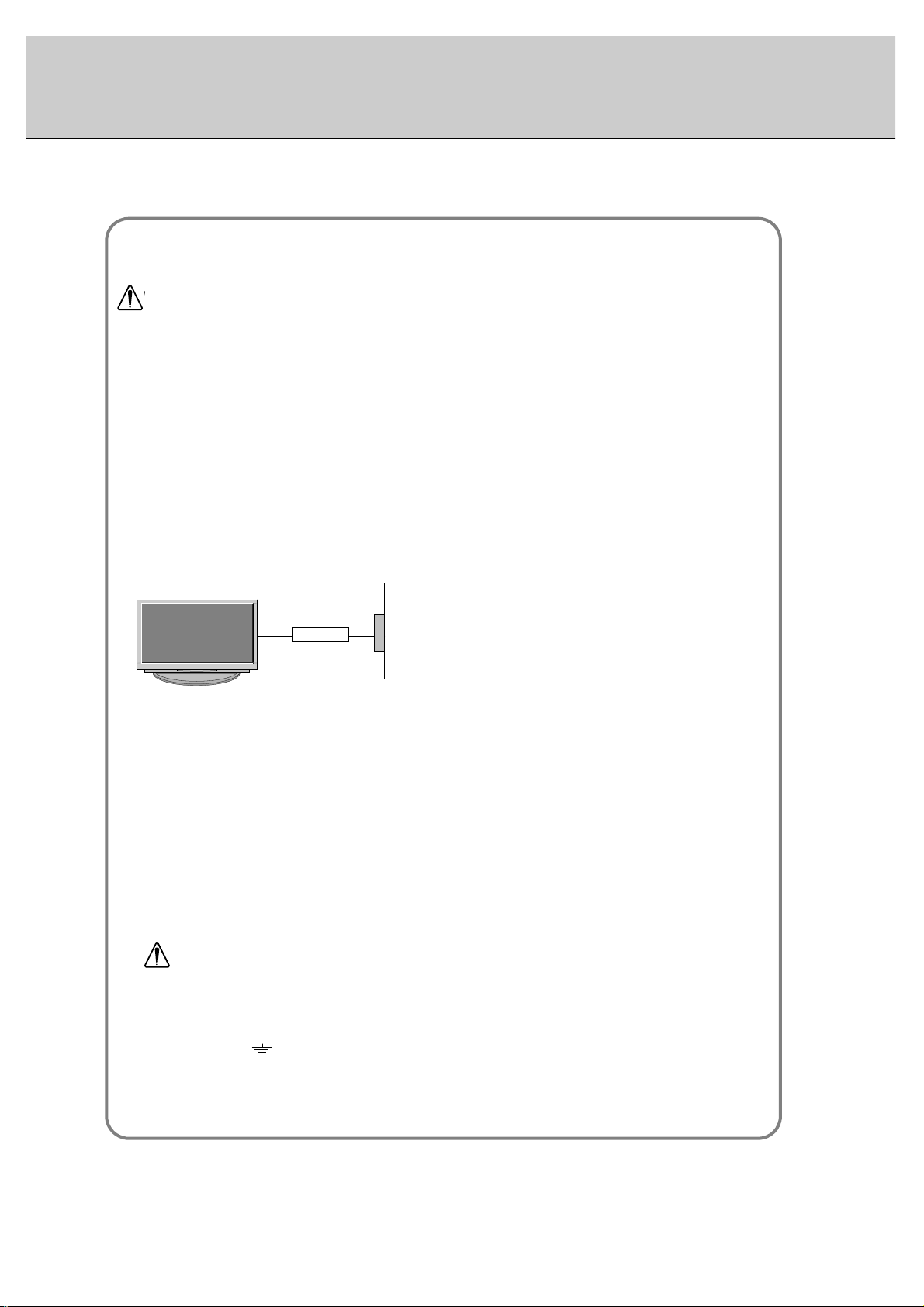
Bend antenna cable between inside and outside
building to prevent rain from flowing in.
- This may cause water damaged inside the Monitor and could
give an electric shock.
Earth wire should be connected.
- If the earth wire is not connected, there is possible a danger of
electric shock caused by the current leakage.
- If grounding methods are not possible, a separate circuit breaker should be employed and installed by a qualified electrician.
- Do not connect ground to telephone wires, lightning rods or gas
pipe.
Do not placing anything containing liquid on top of
the Monitor.
- This may cause a fire or could give an electric shock.
Do not insert any object into the exhaust vent.
- This may cause a fire or could give an electric shock.
Do not place heavy objects on the Monitor.
- This may cause serious injury to a child or adult.
Do not use water the Monitor while cleaning.
- This may cause damaged the Monitor or could give an electric
shock.
In case of smoke or strange smell from the Monitor,
switch it off ,unplug it from the wall outlet and contact
your dealer or service center.
- This may cause a fire or could give an electric shock.
Do not attempt to service the Monitor yourself.
Contact your dealer or service center.
- This may cause damaged the Monitor or could give an electric
shock.
During a lightning thunder, unplug the Monitor from
the wall outlet and don’t touch an antenna cable.
- This may cause damaged the Monitor or could give an electric
shock.
W
WARNING
WARNING
in U.K. only
*
This set is supplied with a BS 1363 approved 13 amp mains plug, fused at 13 amp. When replacing the fuse
always use a 13 amp BS 1362, BSI or ASTA approved type. Never use this plug with the fuse cover omitted. To
obtain a replacement fuse cover contact your dealer or “LG Electronics U.K. Ltd.” If the type of plug supplied is not
suitable for the mains sockets in your home, then the plug should be removed and a suitable type fitted.
A mains plug removed from the mains lead of this set must be destroyed. A mains plug with bared wires is
hazardous if inserted in a mains socket. Do not connect either wire to the earth pin, marked with the letter E or
with the earth symbol or coloured green or green and yellow. If any other plug is fitted, use a 13 amp fuse,
either in the plug, or at the distribution board.
The wires in this mains lead are coloured in accordance with the following codes:
As the colours of the wires in the mains lead of this set may not correspond with the coloured marking identifying the terminals in your plug, proceed as follows: The wire which is coloured blue must be connected to the terminal which is marked with the letter N or coloured black. The wire which is coloured brown must be connected
to the terminal which is marked with the letter L or coloured red.
BLUE: NEUTRAL, BROWN: LIVE
Short-circuit
breaker
Power
supplier
- Use the Monitor at the place lower than the altitude of 6562 feet (2000m) to get the best quality of picture
and sound.
5
This plasma display is designed to be mounted horizontally (wide viewing).
Never touch the power plug with a wet hand.
- This may cause an electric shock.
Disconnect from the mains and remove all connections before moving.
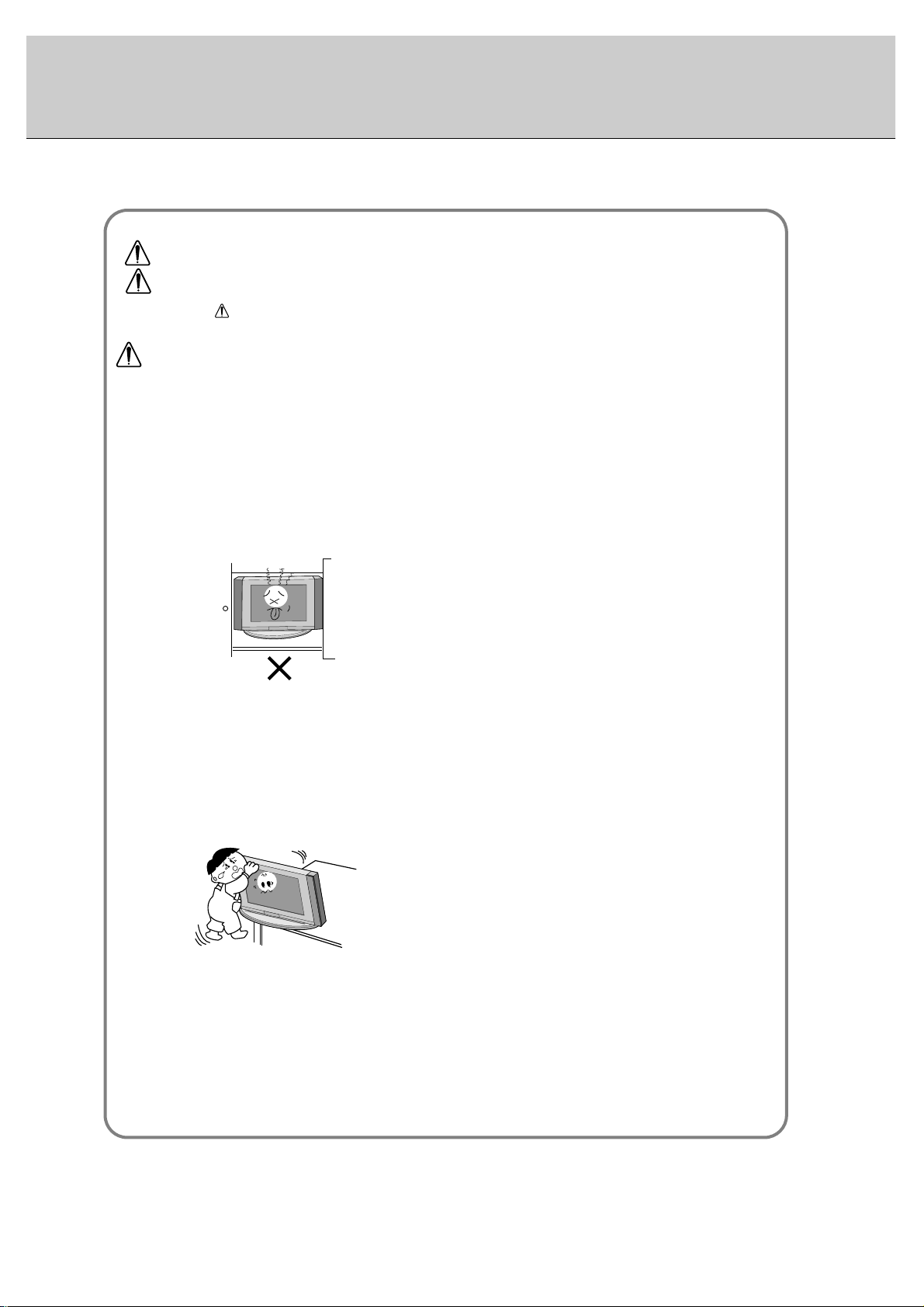
Do not place the Monitor in a built-in installation such
as a bookcase or rack.
- Ventilation required.
When installing the Monitor on a table, be careful not
to place the edge of its stand.
- This may cause the Monitor to fall, causing serious injury to a
child or adult, and serious damage to the Monitor.
Do not place an outside antenna in the vicinity of overhead power lines or other electric light or power circuits.
- This may cause an electric shock.
There should be enough distance between an outside
antenna and power lines to keep the former from
touching the latter even when the antenna falls.
- This may cause an electric shock.
Do not pull the cord but the plug when unplugging.
- This may cause a fire.
Ensure the power cord doesn’t trail across any hot
objects like a heater.
- This may cause a fire or an electric shock.
Do not plug when the power cord or the plug is damaged or the connecting part of the power outlet is
loose.
- This may cause a fire or an electric shock.
Dispose of used batteries carefully to protect a child
from eating them.
- In case that it eats them, take it to see a doctor immediately.
When moving the Monitor assembled with speakers do
not carry holding the speakers.
- This may cause the Monitor to fall, causing serious injury to a
child or adult, and serious damage to the Monitor.
Unplug this product from the wall outlet before cleaning. Do not use liquid cleaners or aerosol cleaners.
- This may cause damaged the Monitor or could give an electric
shock.
Contact the service center once a year to clean the
internal part of the Monitor.
- Accumulated dust can cause mechanical failure.
The distance between eyes and the screen should be
about 5 ~ 7 times as long as diagonal length of the
screen.
- If not, eyes will strain.
Unplug the Monitor from the wall outlet when it is left
unattended and unused for long periods of time.
- Accumulated dust may cause a fire or an electric shock from
deterioration or electric leakage.
Only use the specified batteries.
- This make cause damaged the Monitor or could give an electric
shock.
NOTE
*
Safety instructions have two kinds of information, and each meaning of it is as below.
Take care of danger that may happen under specific condition.
The violation of this instruction may cause serious injuries and even death.
The violation of this instruction may cause light injuries or damage of the
product.
WARNING
NOTES
Connection to PC
Connection to AV equipment
6
AC INPUT
(8Ω)
EXTERNAL SPEAKER
( )( )
R
COMPONENT(480i/480p)
(DVD INPUT)
AUDIO
INPUT
VIDEO
INPUT
AUDIO
INPUT
AUDIO
INPUT
RGB1 OUTPUT
(PC OUTPUT)
RGB1 INPUT
(PC INPUT)
RGB2 INPUT
(DIGITAL RGB INPUT)
RS-232C INPUT
(CONTROL/SERVICE)
( )( )
L
S-VIDEO
(8Ω)
EXTERNAL SPEAKER
(MONO)
R
AUDIO
L
Y PBP
R
R
AUDIO
L
<Back Panel>
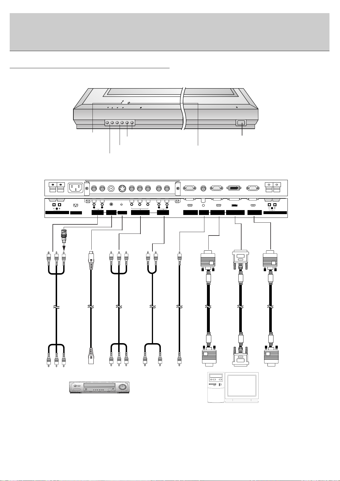
Controls of the Monitor
ON/OFF
VOL
MENU
INPUT SELECT
<Front Panel Controls>
Main power button
INPUT SELECT button
VOLUME (FF,GG) buttons
Power standby indicator
Illuminates red in standby
mode. Illuminates green
when the Monitor is turned
on
Remote control sensor
MENU button
DD,EE
buttons
AUDIO INPUT
VIDEO
INPUT
COMPONENT
(DVD INPUT)
S-VIDEO
INPUT
AUDIO INPUT
AUDIO INPUT
RGB1 INPUT
(PC INPUT)
RGB2 INPUT
(DIGITAL
RGB INPUT)
RS-232C
INPUT
Note : All cables shown are not provided with the Monitor,
except : A D-sub 15 pin cable and DVI cable is supplied to connect the Monitor to a PC.
AC INPUT
(8Ω)
EXTERNAL SPEAKER
( )( )
R
RGB1 OUTPUT
(PC OUTPUT)
AUDIO
INPUT
RGB1 INPUT
(PC INPUT)
RGB2 INPUT
(DIGITAL RGB INPUT)
RS-232C INPUT
(CONTROL/SERVICE)
( )( )
L
(8Ω)
EXTERNAL SPEAKER
AV1AV1
7
Watching External Equipments
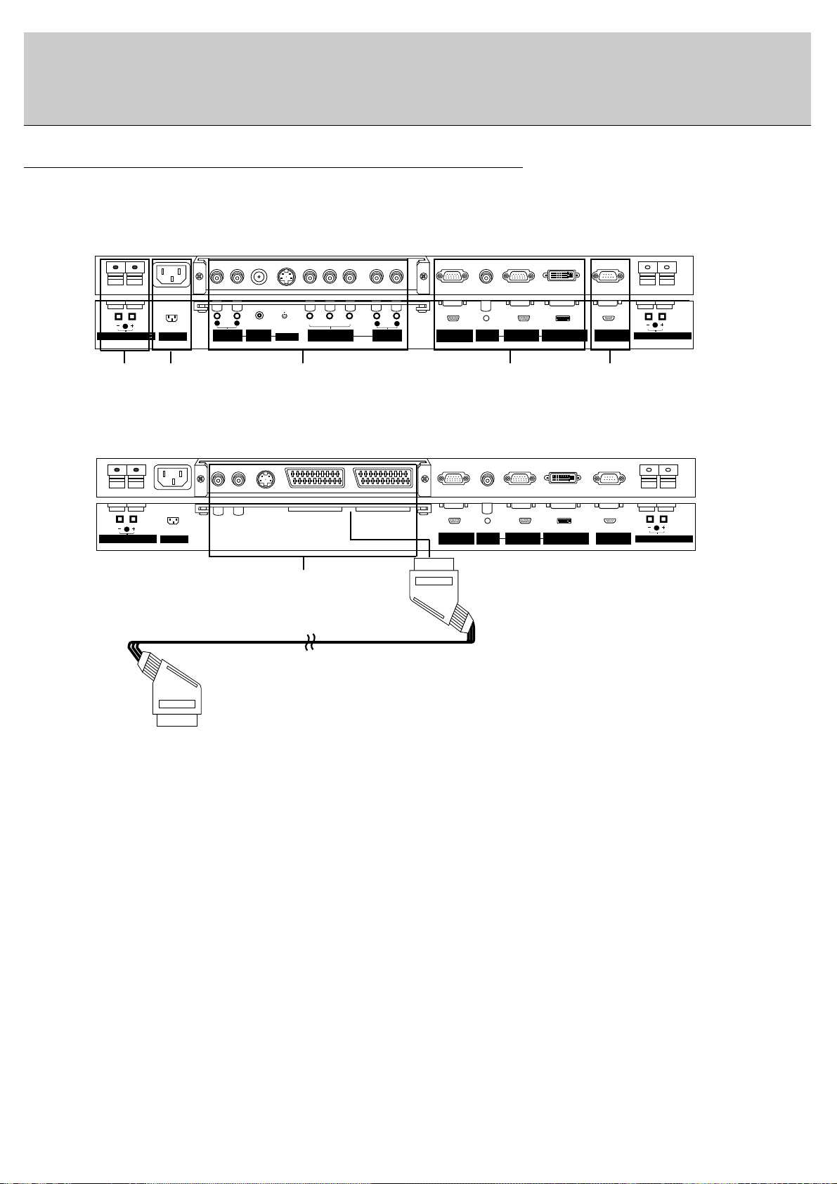
<Back Panel>
RCA Type
Scart Type
1 2 3 4 5
1. EXTERNAL SPEAKER (8 ohm output)
Connect this terminal to the optionally available speaker.
*For further information, refer to ‘Speaker & Speaker
stand’ manual.
2. POWER INPUT SOCKET
This Monitor operates on an AC mains supply, the voltage
is as indicated as inside back cover of this manual. Never
apply DC power to the Monitor.
3. VIDEO/S-VIDEO/COMPONENT(DVD INPUT)/AUDIO
INPUT SOCKETS
EURO SCART SOCKET
Note : The interface board(AP-50EA40/41) is not
equipped on MT/MZ-50PZ42/43 series models. Contact
your dealer for buying this optional item.
4. RGB1 OUTPUT(PC OUTPUT)/AUDIO IN SOCKETS
You can watch the RGB1 signal in other monitor by connecting RGB1 OUTPUT(PC OUTPUT) to other monitor’s
PC input jack.
Note : When you watch after connecting with other monitor,
a. When you select RGB1 or RGB2 for main picture, you
can watch AV1, AV2 or S-Video for sub picture.
b. When you select AV1, AV2 or S-Video for main picture, You can watch main picture’s viewing.
RGB1 INPUT(PC INPUT)/RGB2 INPUT(DIGITAL RGB
INPUT) IN SOCKETS
Connect the monitor output socket of the PERSONAL
COMPUTER to this socket.
5. RS-232C INPUT(CONTROL/SERVICE) SOCKET
Connect it to the RS-232C socket on the PC.
3
( )( )
R
EXTERNAL SPEAKER
(MONO)
L
AUDIO
R
AUDIO
(8Ω)
AC INPUT
INPUT
VIDEO
INPUT
Y PBP
S-VIDEO
R
COMPONENT(480i/480p)
(DVD INPUT)
L
AUDIO
R
AUDIO
INPUT
RGB1 OUTPUT
(PC OUTPUT)
AUDIO
INPUT
RGB1 INPUT
(PC INPUT)
RGB2 INPUT
(DIGITAL RGB INPUT)
RS-232C INPUT
(CONTROL/SERVICE)
( )( )
L
EXTERNAL SPEAKER
(8Ω)
8
Watching VCR (When the Interface board is installed.)
The interface board(AP-50EA40/41) is not equipped on MT/MZ-50PZ42/43 series models.
When connecting the Plasma Monitor with external equipments, match the colours of connecting ports (Video - yellow,
Audio(L) - white, Audio(R) -red).
Connect the VIDEO INPUT socket(yellow) with the BNC-RCA adapter to the VIDEO INPUT socket of the set.
If you have a mono VCR, connect the audio cable from the VCR to the AUDIO(L/MONO) input of the Plasma Monitor.
If you connect an S-VIDEO VCR to the S-VIDEO input, the picture quality is improved; compared to connecting a regular VCR to the Video input.
Or, connect the Euro scart socket of the VCR to the Euro scart socket of the set.
Avoid having a fixed image remain on the screen for a long period of time. Typically a frozen still picture from a VCR,
4:3 picture format or if a CH label is present; the fixed image may remain visible on the screen.
Use the orbiter function to avoid having a fixed image. (Refer to p.18)
1. Press INPUT SELECT button on the remote control and select
Video
or (
AV1
or
AV2
).
(When connecting with S-Video, select the
S-Video
)
2. Insert a video tape into the VCR and press the PLAY button on the VCR. (See VCR owner ’s manual)
Watching external AV source (When the Interface board is installed.)
The interface board(AP-50EA40/41) is not equipped on MT/MZ-50PZ42/43 series models.
When connecting the Plasma Monitor with external equipments, match the colours of connecting ports.
Or, connect the Euro scart socket of the VCR to the Euro scart socket of the set.
1. Press INPUT SELECT button on the remote control of the monitor to select
Video
or (
AV1
or
AV2
).
2. Operate the corresponding external equipment. (See external equipment operating guide.)
Watching Cable TV (When the Interface board is installed.)
The interface board(AP-50EA40/41) is not equipped on MT/MZ-50PZ42/43 series models.
After subscribing to a cable TV service from a local provider and installing a converter, you can watch cable TV program-
ming. This monitor cannot display TV programming without a TV tuner device or cable TV converter box connected to the
monitor.
1. Press INPUT SELECT button on the remote control and select
Video
or (
AV1
or
AV2
).
2. Tune to cable service provided channels using the cable box.
• Component Input ports
You can get better picture quality if you connect DVD player with component input ports
as below.
Component ports of the
Monitor
Y
PB
PR
Video output ports
of DVD player
Y
Y
Y
Y
Pb
B-Y
Cb
PB
Pr
R-Y
Cr
P
R
Watching DVD (When the Interface board is installed.)
The interface board(AP-50EA40/41) is not equipped on MT/MZ50PZ42/43 series models.
How to connect
Connect DVD video inputs to Y, P
B
, PRof COMPONENT (DVD
INPUT) and audio inputs to Audio sockets of AUDIO INPUT.
Or, connect the Euro scart socket of the VCR to the Euro scart socket
of the set.
How to use
1. Press INPUT SELECT button on the remote control of the monitor to
select
Component
or (
AV1
or
AV2
).
2. Try this after turning on the DVD player.
(Refer to the DVD player's manual for operating instructions.)

9
• For further information regarding cable TV service, contact your local cable TV service provider(s).
• To avoid picture noise (interference), leave an adequate distance between the VCR and monitor.
• To avoid burning an image on the Monitor screen, don’t have a still picture on the screen for a long period time.
Connecting PC
- To enjoy vivid picture and sound, connect a PC to the Monitor.
- Avoid keeping a fixed image on the monitor’s screen for a long period of time. The fixed image may become permanently imprinted on the screen; use a screen saver when possible.
- Connect PC to the RGB1 INPUT(PC INPUT) or RGB2 INPUT(DIGITAL RGB INPUT) ports of the Monitor after changing
the resolution of PC.
- There might be a noise according to some resolution, vertical pattern, contrast or brightness in PC mode. Then change
the PC mode into other resolution or change the refresh rate into other rate or adjust the brightness and contrast on the
menu until the picture is clean. If the refresh rate of the PC graphic card can not be changed, change the PC graphic card
or consult it to the manufacturer of the PC graphic card.
- Synchronization input form; Separate
Setup Instructions to Connect a PC to your Monitor
- If the resolution of PC is over UXGA, there will be no picture on the Monitor.
- We recommend 1024x768 60Hz as the PC mode providing the best picture quality.
- Connect the signal cable from the monitor output port of the PC to the RGB1 INPUT(PC INPUT) port of the Monitor or the
signal cable from the DVI output port of the PC to the RGB2 INPUT(DIGITALRGB INPUT) port on the Monitor.
- Connect the audio cable from the PC to the Audio input on the Monitor. (Audio cables are not included with the Monitor).
- If using a sound card, adjust PC sound as required.
- This monitor apply a VESAPlug and Play Solution. The monitor provides EDID data to the PC system with a DDC protocol. The PC adjusts automatically to use this monitor.
- DDC protocol is preset for RGB1 (Analog RGB), RGB2 (DVI, Digital RGB) mode.
- If required, adjust the monitor settings for Plug and Play functionally.
- If graphic card on the PC does not output analog and digital RGB simultaneously, connect only one of both RGB1 and
RGB2 to display the PC on the monitor.
If graphic card on the PC does output analog and digital RGB simultaneously, set the monitor to either RGB1 or RGB2;
(the other mode is set to Plug and Play automatically by the monitor.)
PC Setup
1. Turn on the PC and apply power to the Monitor.
2. Turn on the display by pressing the POWER button on the Monitor’s remote control.
3. Use the INPUT SELECT button on the remote control to select the RGB1 or RGB2 input source.
4. Set the resolution output of the PC to SXGA or under (1280 x 1024, 75Hz).
10
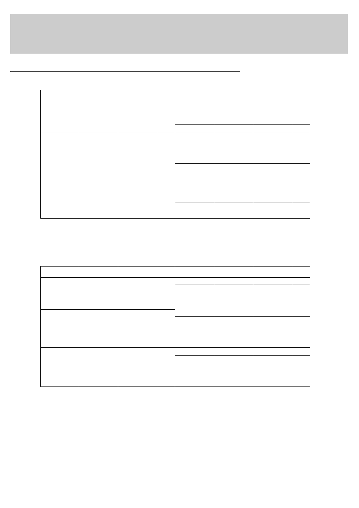
Displayable Monitor Specification
(Synchronization input form : separate)
• DOS mode may not work depending on video card if using a DVI-I cable.
(Synchronization input form : separate)
< RGB1 mode >
< RGB2 mode >
Resolution
640x350
720x400
640x480
800x600
Horizontal
Frequency(KHz)
31.468
37.861
31.469
37.927
31.469
35.000
37.861
37.500
43.269
45.913
53.011
64.062
35.156
37.879
46.875
70.09
85.08
70.08
85.03
59.94
66.66
72.80
75.00
85.00
90.03
100.04
120.00
56.25
60.31
75.00
o
o
o
o
o
o
o
o
o
o
o
o
o
o
o
o
o
o
o
o
o
o
53.674
56.000
64.016
49.725
48.363
56.476
60.023
68.677
54.348
63.995
67.500
77.487
75.000
63.981
79.976
85.06
90.00
100.00
74.55
60.00
70.06
75.02
84.99
60.05
70.01
75.00
85.05
75.00
60.02
75.02
Vertical
Frequency(Hz)
DDC DDCResolution
800x600
832x624
1024x768
1152x864
1280x960
1280x1024
Horizontal
Frequency(KHz)
Vertical
Frequency(Hz)
Resolution
640x480
800x600
Horizontal
Frequency(KHz)
31.468
37.861
31.469
37.927
31.469
35.000
37.861
37.500
43.269
35.156
37.879
48.077
46.875
53.674
70.09
85.08
70.08
85.03
59.94
66.66
72.80
75.00
85.00
56.25
60.31
72.18
75.00
85.06
o
o
o
o
o
o
o
o
o
o
o
o
o
49.725
48.363
56.476
60.023
68.677
54.348
63.995
67.500
77.487
68.681
60.000
75.000
63.981
74.55
60.00
70.06
75.02
84.99
60.05
70.01
75.00
85.05
75.06
60.00
75.00
60.02
Vertical
Frequency(Hz)
DDC DDCResolution
Vertical
Frequency(Hz)
o
o
o
o
o
o
o
o
o
o
o
832x624
1024x768
1152x870
1280x960
1280x1024
1152x864
Horizontal
Frequency(KHz)
640x350
720x400
 Loading...