

LG MT-50PZ41VB, MT-50PZ41, MT-50PZ41VS, MT-50PZ43, MZ-50PZ43 Service Manual
...
OKVOLCH
PLASMA MONITOR
SERVICE MANUAL
CAUTION
BEFORE SERVICING THE CHASSIS,
READ THE SAFETY PRECAUTIONS IN THIS MANUAL.
CHASSIS : RF-02CA
MODEL : MT-50PZ40
MODEL : MT-50PZ41/H/V/VB/VS
MODEL : MT/MZ-50PZ43/M/S/V/VS
MODEL : MZ-50PZ42/42S
website:http://biz.LGservice.com
e-mail:http://www.LGEservice.com/techsup.html

- 2 -
CONTENTS
SAFETY PRECAUTIONS ...................................................................................3
DISCRIPTION OF CONTROLS ......................................................................... 4
ADJUSTMENT INSTRUCTIONS ........................................................................8
BLOCK DIAGRAM.............................................................................................11
EXPLODED VIEW..............................................................................................12
EXPLODED VIEW PARTS LIST........................................................................13
REPLACEMENT PARTS LIST...........................................................................14
SCHEMATIC DIAGRAM ........................................................................................
PRINTED CIRCUIT BOARD ..................................................................................
- 3 -
SAFETY PRECAUTIONS
Many electrical and mechanical parts in this chassis have special safety-related characteristics. These parts are identified by in
the Schematic Diagram and Replacement Parts List.
It is essential that these special safety parts should be replaced with the same components as recommended in this manual to
prevent X-RADIATION, Shock, Fire, or other Hazards.
Do not modify the original design without permission of manufacturer.
General Guidance
An lsolation Transformer should always be used during
the servicing of a receiver whose chassis is not isolated from
the AC power line. Use a transformer of adequate power rating
as this protects the technician from accidents resulting in
personal injury from electrical shocks.
It will also protect the receiver and it's components from being
damaged by accidental shorts of the circuitary that may be
inadvertently introduced during the service operation.
If any fuse (or Fusible Resistor) in this monitor is blown, replace
it with the specified.
When replacing a high wattage resistor (Oxide Metal Film
Resistor, over 1W), keep the resistor 10mm away from PCB.
Keep wires away from high voltage or high temperature parts.
Due to high vacuum and large surface area of picture tube,
extreme care should be used in handling the Picture Tube.
Do not lift the Picture tube by it's Neck.
Leakage Current Cold Check(Antenna Cold Check)
With the instrument AC plug removed from AC source,
connect an electrical jumper across the two AC plug prongs.
Place the AC switch in the on positioin, connect one lead of
ohm-meter to the AC plug prongs tied together and touch other
ohm-meter lead in turn to each exposed metallic parts such as
antenna terminals, phone jacks, etc.
If the exposed metallic part has a return path to the chassis, the
measured resistance should be between 1MΩ and 5.2MΩ.
When the exposed metal has no return path to the chassis the
reading must be infinite.
An other abnormality exists that must be corrected before the
receiver is returned to the customer.
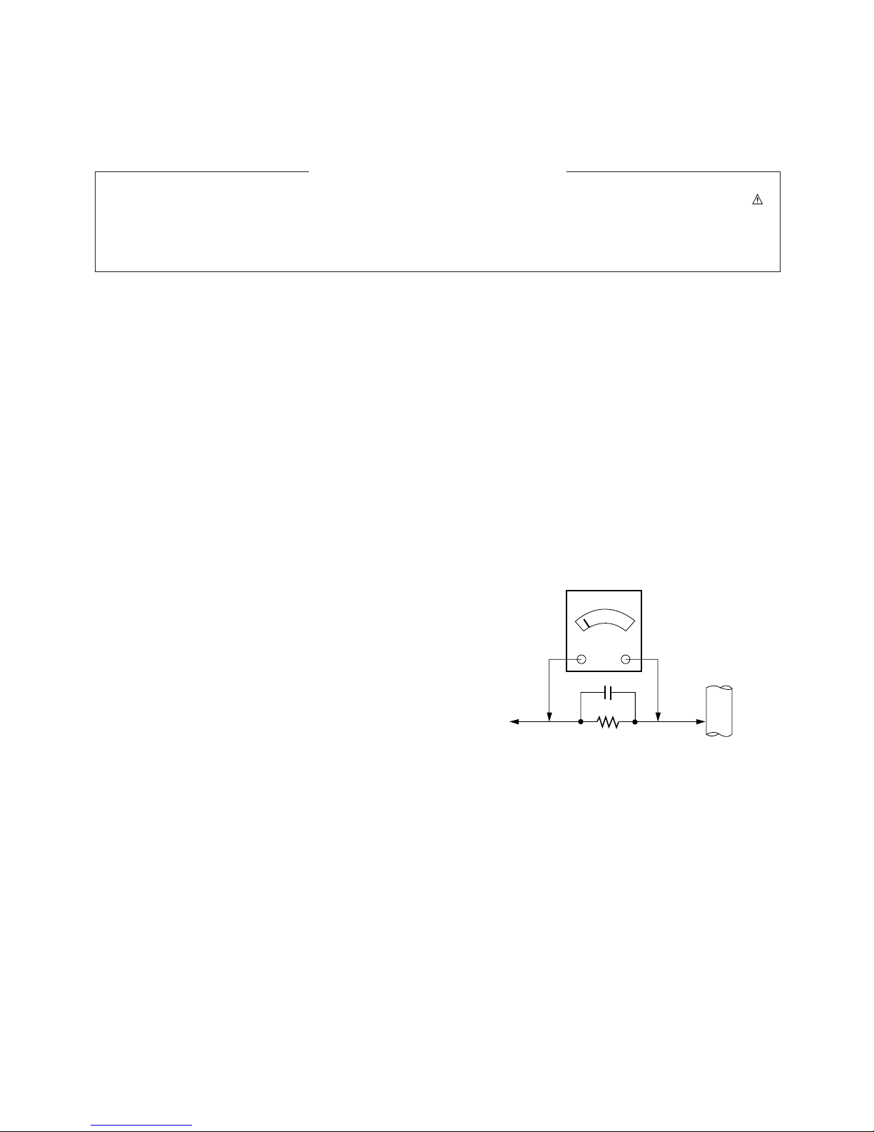
Leakage Current Hot Check (See below Figure)
Plug the AC cord directly into the AC outlet.
Do not use a line Isolation Transformer during this check.
Connect 1.5K/10watt resistor in parallel with a 0.15uF capacitor
between a known good earth ground (Water Pipe, Conduit, etc.)
and the exposed metallic parts.
Measure the AC voltage across the resistor using AC
voltmeter with 1000 ohms/volt or more sensitivity.
Reverse plug the AC cord into the AC outlet and repeat AC
voltage measurements for each esposed metallic part. Any
voltage measured must not exceed 0.75 volt RMS which is
corresponds to 0.5mA.
In case any measurement is out of the limits sepcified, there is
possibility of shock hazard and the set must be checked and
repaired before it is returned to the customer.
Leakage Current Hot Check circuit
1.5 Kohm/10W
To Instrument's
exposed
METALLIC PARTS
Good Earth Ground
such as WATER PIPE,
CONDUIT etc.
AC Volt-meter
IMPORTANT SAFETY NOTICE
0.15uF
- 4 -
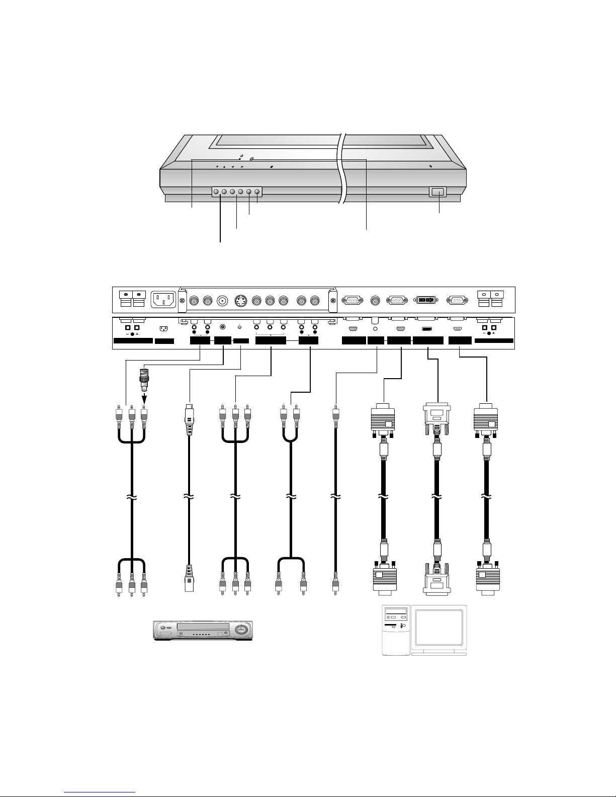
CONTROLS DESCRIPTION
Connection to PC
Connection to AV equipment
AC INPUT
(8Ω)
EXTERNAL SPEAKER
( )( )
R
COMPONENT(480i/480p)
(DVD INPUT)
AUDIO
INPUT
VIDEO
INPUT
AUDIO
INPUT
AUDIO
INPUT
RGB1 OUTPUT
(PC OUTPUT)
RGB1 INPUT
(PC INPUT)
RGB2 INPUT
(DIGITAL RGB INPUT)
RS-232C INPUT
(CONTROL/SERVICE)
( )( )
L
S-VIDEO
(8Ω)
EXTERNAL SPEAKER
(MONO)
R
AUDIO
L
YPBP
R
R
AUDIO
L
<Back Panel>
ON/OFF
VOL
MENU
INPUT SELECT
<Front Panel Controls>
Main power button
INPUT SELECT button
VOLUME (FF,GG) buttons
Power standby indicator
Illuminates red in standby
mode. Illuminates green
when the Monitor is turned
on
Remote control sensor
MENU button
DD,EE
buttons
AUDIO INPUT
VIDEO
INPUT
COMPONENT
(DVD INPUT)
S-VIDEO
INPUT
AUDIO INPUT
AUDIO INPUT
RGB1 INPUT
(PC INPUT)
RGB2 INPUT
(DIGITAL
RGB INPUT)
RS-232C
INPUT
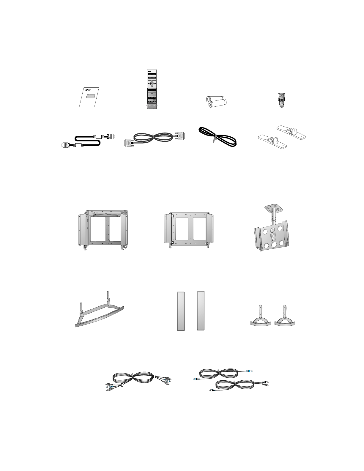
Note : All cables shown are not provided with the Monitor,
except : A D-sub 15 pin cable and DVI cable is supplied to connect the Monitor to a PC.
- 5 -
AC INPUT
(8Ω)
EXTERNAL SPEAKER
( )( )
R
RGB1 OUTPUT
(PC OUTPUT)
AUDIO
INPUT
RGB1 INPUT
(PC INPUT)
RGB2 INPUT
(DIGITAL RGB INPUT)
RS-232C INPUT
(CONTROL/SERVICE)
( )( )
L
(8Ω)
EXTERNAL SPEAKER
AV1AV1
AC INPUT
(8Ω)
EXTERNAL SPEAKER
( )( )
R
COMPONENT(480i/480p)
(DVD INPUT)
AUDIO
INPUT
VIDEO
INPUT
AUDIO
INPUT
AUDIO
INPUT
RGB1 OUTPUT
(PC OUTPUT)
RGB1 INPUT
(PC INPUT)
RGB2 INPUT
(DIGITAL RGB INPUT)
RS-232C INPUT
(CONTROL/SERVICE)
( )( )
L
S-VIDEO
(8Ω)
EXTERNAL SPEAKER
Y PBP
R
(MONO)
R
AUDIO
L
R
AUDIO
L
<Back Panel>
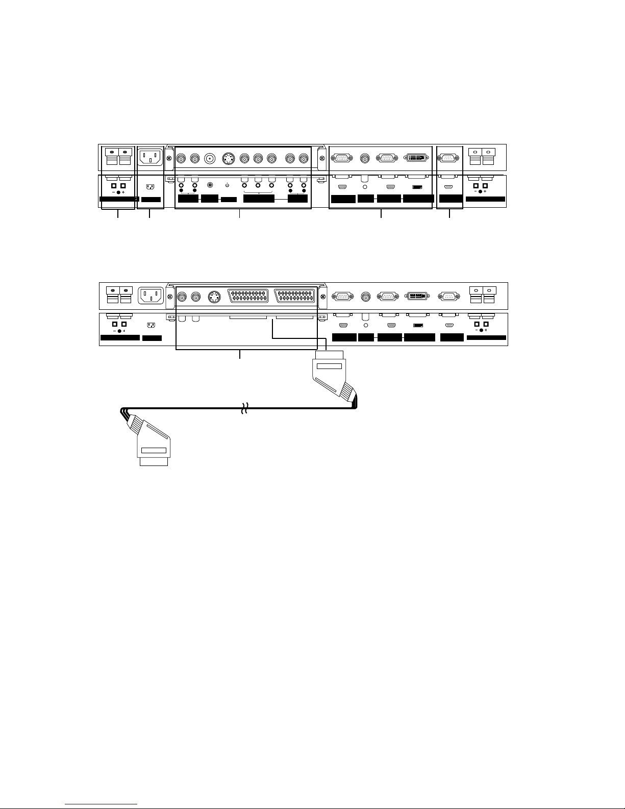
Socket Type
Scart Type
1 2 3 4 5
1. EXTERNAL SPEAKER (8 ohm output)
Connect this terminal to the optionally available speaker.
*For further information, refer to ‘Speaker & Speaker
stand’ manual.
2. POWER INPUT SOCKET
This Monitor operates on an AC mains supply, the voltage
is as indicated as inside back cover of this manual. Never
apply DC power to the Monitor.
3. VIDEO/S-VIDEO/COMPONENT(DVD INPUT)/AUDIO
INPUT SOCKETS
EURO SCART SOCKET
Note : The interface board(AP-50EA40/41) is not
equipped on MT/MZ-50PZ41/43 series models. Contact
your dealer for buying this optional item.
4. RGB1 OUTPUT(PC OUTPUT)/AUDIO IN SOCKETS
You can watch the RGB1 signal in other monitor by connecting RGB1 OUTPUT(PC OUTPUT) to other monitor’s
PC input jack.
Note : When you watch after connecting with other monitor,
a. When you select RGB1 or RGB2 for main picture, you
can watch AV1, AV2 or S-Video for sub picture.
b. When you select AV1, AV2 or S-Video for main picture, You can watch main picture’s viewing.
RGB1 INPUT(PC INPUT)/RGB2 INPUT(DIGITAL RGB
INPUT) IN SOCKETS
Connect the monitor output socket of the PERSONAL
COMPUTER to this socket.
5. RS-232C INPUT(CONTROL/SERVICE) SOCKET
Connect it to the RS-232C socket on the PC.
3
- 6 -
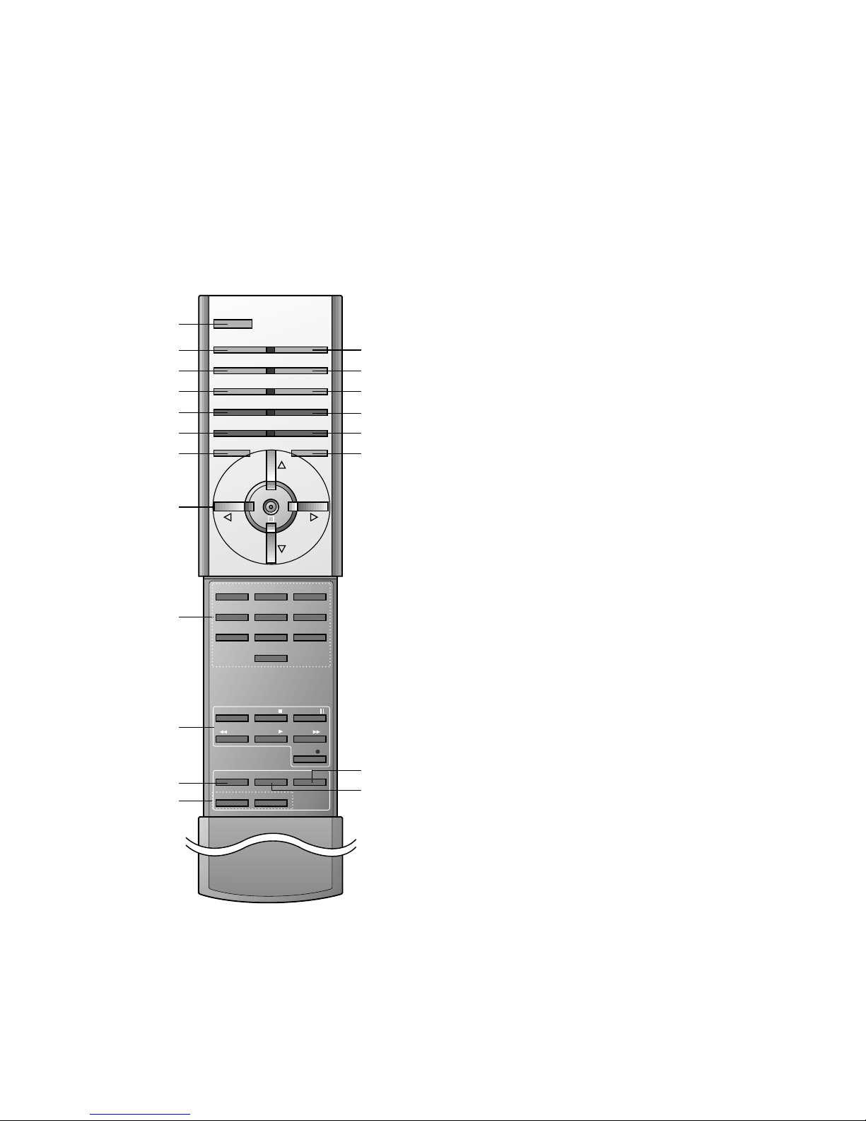
- When using the remote control aim it at the remote control sensor of the Monitor.
1 2 3
4 5 6
7 8
0
9
POWER
SLEEP INPUT SELECT
PSM SSM
ARC PIP ARC
PIP
TWIN PICTURE
SWAP
MENU MUTE
OK
VOL
POWER STOP
PLAY FF
REC
REW
P/STILL
WIN.SIZE
WIN.POSITION
ZOOM +
ZOOM -
SPLIT ZOOM
VOL
SUB INPUT
1. POWER
switches the set on from standby or off to standby.
2. SLEEP
sets the sleep timer.
3. PSM (Picture Status Memory)
recalls your preferred picture setting.
4. ARC (Aspect Ratio Control)
changes the picture format.
5. PIP
switches the sub picture on or off.
6. SWAP
alternates between main and sub picture.
7. MENU Button
selects a menu.
8.
DD/ EE
selects a menu item.
FF/ GG
(Volume Down/Up)
adjusts the volume.
adjusts menu settings.
OK
displays the current mode.
9. NUMBER BUTTONS
10. VCR BUTTONS
control a LG video cassette recorder.
11. WIN. SIZE
adjusts the sub picture size.
12. ZOOM-/ZOOM+
13. INPUT SELECT BUTTON
selects TV, AV or PC monitor mode.
14. SSM (Sound Status Memory)
recalls your preferred sound setting.
15. PIP ARC
changes the picture format of PIP.
16. TWIN PICTURE
17. SUB INPUT
selects the input mode for the sub picture.
18. MUTE Button
switches the sound on or off.
19. SPLIT ZOOM
enlarge the screen with regular ration.
20. WIN.POSITION
moves the sub picture to
DD/ EE
or FF/ GGdirection.
1
13
14
15
16
17
18
19
20
2
3
4
5
6
7
8
9
10
11
12
- 7 -
D-sub 15 pin cable
AS mark
LG TV
Owner’s Manual
1.5V
1.5V
Alkaline batteries
BNC-RCA adapter (optional)
DVI cable
Power cord
1 2 3
4 5 6
7 809
POWER
SLEEP INPUT SELECT
PSM SSM
ARC PIP ARC
PIP
TWIN PICTURE
SWAP
MENU MUTE
OK
VOL
POWER STOP
PLAY FF
REC
REW
P/STILL
WIN.SIZE
WIN.POSITION
ZOOM +
ZOOM -
SPLIT ZOOM
VOL
SUB INPUT
Remote control handset
Simple monitor stand
Ceiling mounting bracket
- Optional extras can be changed or modified for quality improvement without any notification new optional extras can be
added.
- Contract your dealer for buying these items.
Accessories
Optional Extras
Tilt wall mounting bracket
Wall mounting bracket
Video cables
Desktop stand
Desktop Speaker stand
Speakers
PC audio cables

1. Application Object
These instructions are applied to all of the PDP monitor, RF02CA.
2. Notes
(1) Because this is not a hot chassis, it is not necessary to use
an isolation transformer. However, the use of isolation
transformer will help protect test instrument.
(2) Adjustment must be done in the correct order.
(3) The adjustment must be performed in the circumstance of
25±5°C of temperature and 65±10% of relative humidity if
there is no specific designation.
(4) The input voltage of the receiver must keep 110~240V,
50/60Hz in adjusting.
(5) The receiver must be operated for about 15 minutes prior
to the adjustment.
1) After receiving 100% white pattern(06CH), the receiver
must be operate prior to adjustment. (Or white condition
in HEAT-RUN mode)
2) Enter into HEAT-RUN mode
- Press the POWER ON KEY on R/C for adjustment.
- OSD display HEAT-RUN WHITE and screen display
100% full WHITE PATTERN.
[ Set is activated HEAT-RUN without signal generator in
this mode.
[ Single color pattern of HEAT-RUN mode uses to check
PANEL. (RED/BLUE/GREEN)
[Caution]
If you turn on a still screen more than 20 minutes
(Especially Digital pattern(13 CH), Cross Hatch
Pattern), a afterimage may be occur in the black level
part of the screen.
3. RGB Auto Cut-Off & MIN Bias
Adjustment
(1) Input Full Back (0 Gray) signal which generated from
Pattern Generator into CVBS and RGB1 Input part.
(2) Press POWER ON KEY on R/C for adjustment and select
AUTO-CUT(Cut-off Auto Adjustment)
(3) Press Vol. + key and operate TO SET
(4) Screen adjustment starts with Full Black screen.
Original Window screen will be presented about 5-6
seconds later. And if there is a mark of OK OSD, then the
Auto Cut-off and Min-Bias adjustment will be completed.
(5) Pass to the next MAX Bias Adjustment after Adjustment.
[ Replace PDP Module or Power Board, adjust certainly Power
PCB Assy Voltage.
4. MAX Bias Adjustment
(1) Input Full White (255 Gray) signal which generated from
Pattern Generator into CVBS and RGB1 Input part.
(2) Press POWER ON KEY on R/C for adjustment and select
MAX-BIAS
(3) Press Vol. + key and operate TO SET
(4) Original Full White screen will be presented about 1~2
seconds later. And if there is a mark of OK OSD, then the
Min-Bias adjustment will be completed.
(5) After adjustment, press
¥
key to save adjustment and
come out of the adjustment mode.
O
You can check whether circuit adjustment is operated well or
not, as below.
(1) Display RGB1 to the Main picture, CVBS to the Sub
picture in the TWIN PICTURE.
(2) To check the MIN-Bias, input Full Black (0 gray) signal into
CVBS and RGB1 input part at the same time in the Pattern
Generator.
(3) To check the MAX-Bias, input Full White (255 gray) signal
into CVBS and RGB1 input part at the same time in the
Pattern Generator.
(4) Compare Black Level with White Level by eyes. And if
there is no Level difference, the adjustment is completed
well.
O
Data value, which adjusted in the board, is valid until the VSC
Board is dissued and must be protected. For the protection of
data, Micom does not permit any more adjustment after
completion.
O
In case of re-adjustment, operate First Value Setting.
Each PCB Assy must be checked by Check JIG Set before
assembly. (Especially, be careful Power PCB Assy which can
cause fatal Damage to PDP Module.)
5. POWER PCB Assy Voltage
Adjustment
(Va, Vs Voltage Adjustment)
5-1 Test Equipment :D.M.M 1EA
5-2 Connection Diagram for Measuring
Refer to Fig 1.
5-3 Adjustment Method
(1) Va Adjustment
1) After receiving 100% white pattern, HEAT RUN.
2) Connect + terminal of D.M.M to Va pin of P805 and
connect – terminal to GND pin of P805.
3) After turning the VR4, voltage of D.M.M adjustment as
same as Va voltage which on label of panel Right/Top.
(Deviation : ±0.5V)
- 8 -
ADJUSTMENT INSTRUCTIONS
 Loading...