

LG MT-50PM10 Owner’s Manual

PLASMA
MONITOR
OWNER'S
MANUAL
Please
Retain
Record
See
mation
the
read
it
for
model
label
to
your
this
future
number
attached
dealer
manual
reference.
and
on
when
carefully
before
serial
the
you
back
number
require
cover
operating
of
and
service.
the
quote
set.
your
this
set.
infor-
Model
Serial
number
number
:
:
P/NO
:
3828VA0513A
(RF04GA,
138D
TX,
026H)
f

Safety
Safety
Safety
Warnings
Instructions
Instructions
-
Use
sound.
Do
sources
-
This
the
W
WARNING
not
place
such
may
cause
set
the
as
at
heat
a
the
set
fire.
place
in
direct
lower
registers,
than
sunlight
stove
and
the
altitude
or
so
near
on.
of
heat
6562
Do
-
feet
not
This
shock.
(2000m)
use
may
water
cause
to
get
the
while
damaged
best
quality
cleaning
the
set
the
or
of
set.
could
picture
give
an
and
electric
Do
or
-
Bend
not
any
This
place
may
antenna
building
-
This
electric
may
use
to
shock.
the
where
cause
prevent
cause
set
a
fire
cable
water
in
damp
it
or
is
could
rain
damaged
place
likely
give
between
from
such
to
get
an
inside
flowing
inside
the
wet.
electric
in.
set
as
shock.
and
and
a
bathroom
could
outside
give
an
In
it
case
off
dealer
-
Do
This
not
your
-
This
of
smoke
,unplug
or
may
dealer
may
service
cause
attempt
cause
or
or
from
it
center.
a
fire
to
service
damaged
strange
the
or
could
service
center.
wall
the
smell
outlet
give
the
set
an
set
or
from
and
electric
yourself.
could
the
contact
shock.
give
set,
Contact
an
switch
your
electric
Earth
-
If
electric
-
If
er
wire
the earth wire
shock
grounding
should
should
methods
be
employed
is
caused
be
not
connected.
connected,
by
are
the
not
and
current
possible,
installed
there
leakage.
by
is
possible
a
separate
a
qualified
Power
a
danger
circuit
electrician.
break-
of
shock.
During
wall
-
This
shock.
outlet
a
may
lightning
and
cause
don't
damaged
thunder,
touch
the
unplug
an
antenna
set
or
the
could
set
cable.
give
from
an
the
electric
supplier
Short-circuit
breaker
-
Do
not
connect
ground
to
telephone
wires,
lightning
rods
or
gas
pipe.
Do
set.
-
Do
-
This
This
not
not
place
may
insert
may
cause
cause
anything
a
any
a
fire
object
fire
or
or
containing
could
into
could
give
the
give
an
an
liquid
electric
exhaust
electric
on
shock.
top
vent.
shock.
of
the
Do
-
not
This
place
may
heavy
cause
serious
WARNING
objects
injury
in
on
to
a
U.K.
the
child
set.
or
adult.
only
*
This
set
always
obtain
suitable
A
hazardous
with
either
The
As
mains
the
wires
the
is
use
a
supplied
replacement
for
plug
earth
in
the
in
colours
a
13
the
mains
removed
if
inserted
symbol
plug,
this
of
with
amp
BS
fuse
sockets
in
or
at
mains
the wires
a
BS
1362,
from
a
the
lead
1363
BSI
cover
the
mains
or
in
coloured
contact
your
mains
socket.
distribution
in
are
the
coloured
approved
or
mains
ASTA
your
home,
lead
Do
green
board.
lead
13
amp
approved
dealer
then
in
of
not
or
accordance
of
the
this
connect
green
this
mains
or
plug
set
set
type.
"LG
should
must
either
and
with
may
plug,
Never
fused
use
Electronics
be
be
destroyed.
wire
yellow.
the
not
If
following
correspond
at
this
U.K.
removed
to
any
the
other
13
plug
Ltd."
A
earth
codes:
amp.
with
and
mains
plug
with
When
If
the
a
pin,
the
replacing
the
suitable
plug
is
BLUE:
fuse
type
with
marked
fitted,
coloured
cover
of
plug
type
fitted.
bared
with
use a
NEUTRAL,
marking
the
fuse
omitted.
supplied
wires
the
13
BROWN:
letter
amp
identify-
To
is
not
is
E
fuse,
LIVE
or
2
ing
minal
to
PLASMA
the
the
terminals
which
terminal
MONITOR
is
in
marked
which
your
is
plug,
with
marked
the
proceed
letter
with
the
N
as
or
letter
follows:
coloured
L
or
The
wire
black.
coloured
which
The
wire
red.
is
which
coloured
is
blue
coloured
must
be
brown
connected
must
be
to
the
connected
ter-

Safety
Warnings
*
Safety
WARNING
NOTES
instructions
have
The
The
two
violation
violation
product.
Take
care
kinds
of
danger
of
of
of
information,
this
this
that
instruction
instruction
may
and
each
happen
may
may
under
meaning
cause
cause
specific
of
it
is
serious
light
condition.
as
below.
injuries
injuries
or
and
even
damage
death.
of
the
NOTES
Never
-
This
Disconnect
tions
touch
may
before
cause
the
from
power
an
the
moving.
electric
mains
plug
shock.
with
and
a
wet
remove
hand.
all
connec-
Ensure
objects
-
Do
aged
This
not
or
the
like
may
plug
cause
the
power
a
heater.
when
a
fire
cord
the
connecting
or
doesn't
an
electric
power
part
shock.
cord
of
trail
or
the
across
the
power
plug
any
is
dam-
outlet
hot
is
Do
not
bookcase
-
Ventilation
place
or
required.
the
rack.
set
in
a
built-in
installation
such
as
a
loose.
-
This
Dispose
from
-
In
When
eating
case
may
cause
of
that
moving
used
them.
it
eats
the
a
fire
or
an
batteries
them,
set
take
assembled
electric
carefully
it
to
shock.
see
a
doctor
with
to
protect
immediately.
speakers
a
do
child
not
When
place
-
This
installing
the
may
edge
cause
of
the
the
its
set
set
on
stand.
to
fall,
a
table,
causing
be
serious
careful
injury
to
not
a
child
to
or
carry
-
This
adult,
Unplug
ing.
-
This
Do
holding
may
and
this
not
may
cause
serious
use
cause
the
the
speakers.
set
damage
product
liquid
damaged
to
fall,
to
from
cleaners
the
causing
the
the
set
Monitor.
wall
or
serious
or
could
outlet
aerosol
give
injury
before
cleaners.
an
electric
to
a
child
clean-
shock.
or
adult,
and
serious
damage
to
the
set.
Contact
internal
-
The
Accumulated
distance
about
screen.
5
the
part
~
7
service
of
dust
the
can
between
times
center
set.
cause
as
eyes
long
once
mechanical
and
as
diagonal
a
the
year
failure.
screen
to
clean
should
length
of
the
be
the
Do
not
head
cuits.
place
power
an
outside
lines
or
antenna
other
in
electric
the
light
vicinity
or
power
of
over-
cir-
-
If
not,
Unplug
tended
-
Accumulated
deterioration
eyes
the
and
will
set
strain.
from
unused
dust
or
electric
may
the
for
cause
wall
long
leakage.
outlet
periods
a
fire
or
an
when
of
electric
it
time.
is
shock
left
from
unat-
-
There
This
may
should
antenna
touching
-
This
may
cause
and
the
latter
cause
an
be
power
electric
enough
lines
even
an
electric
shock.
distance
to
when
shock.
keep
the
between
the
antenna
an
former
falls.
outside
from
Do
-
not
This
pull
may
the
cause
cord
a
fire.
but the
plug
when
unplugging.
Owner's
Manual
3

Contents
Contents
Contents
Safety
Warnings
SafetyInstructions.......................2~3
Introduction
RemoteControlKeyFunctions................6
LocationandFunctionofControls
Installation
. . . . . . . . . .
.7~9
Special
ChildLock..............................20
ISM
LowPower..............................21
MenuRotationforVerticalViewing.
Screen
Auto
Menu
(Image
Options
Sticking
Minimization)
Method
Demo(option)......................21
. . . . . . . . . .
Menu
adjustment
Options
(RGB
[PC]
mode
only)
. . . . .
. . . . . . .
.20
.21
.22
External
Displayable
Accessories.............................13
InstallationOptions.......................14
Operation
TurningontheSet........................15
On-Screen
Equipment
Monitor
Menu
Viewing
Specification
Language
Setups
. . . . . . . . . . . .
Selection
. . . . . . .
(option)
.10~11
.12
. .
.15
SettingPictureFormat.....................22
ScreenPosition..........................22
Manual
Selecting
Configure
Wide
(RGB
VGA/XGA
[PC]
mode
mode
only)
(RGB[PC]
. . . . . .
mode
ScreenAdjustments.......................23
Cinema................................23
Luminance
Initializing
Noise
(Reset
Reduction
to
original
(option)
factory
. . . . . . . . .
value)
. . . . .
only)
.23
.23
.24
.24
Picture
Menu
Options
PSM(PictureStatusMemory)...............16
..................................16
AdjustingAutoColourControl.
Manual
sRGB
Fleshtone...............................17
Colour
Temperature
(RGB[PC],
DVI[PC]
Control
mode
. . . . . . . . . . . . .
(User
only)
option)
. . . . . . . .
. . .
.16
.16
.17
SplitZoom..............................24
PIP
(Picture
In
Picture)
Feature
WatchingPIP............................25
Selecting
an
Input
Signal
MovingthePIP(PIPmodeonly).
PictureSize.............................25
Adjusting
PIP
Transparency
Source
(PIP
for
. . . . . . . . . . .
mode
the
PIP
only)
. . .
. . .
.25
.25
.25
Manual
Sound
SSM(SoundStatusMemory)................18
BBE...................................18
AVL(AutoVolumeLeveler).................18
Adjusting
Time
SettingtheClock.........................19
Menu
Menu
Picture
Options
Sound
Options
Control
Control
(User
(User
option)
option)
. . . . . . . . .
. . . . . . . .
.17
.18
Miscellaneous
ExternalControlDeviceSetup
IRCode(NECformat)..................32~33
TroubleshootingChecklist..................34
ProductSpecifications.....................35
. . . . . . . . . . .
.26~31
SettingtheOn/OffTimer...................19
AutoSleep..............................19
SleepTimer.............................19
4
After
al,
where
keep
reading
always
PLASMA
it
in
the
contact
this
the
user
MONITOR
manu-
place
can
easily.

Introduction
Introduction
Introduction
What
If
voltage
light
160°
A
Plasma
is
is
emitted.
-
a
is
Wide
Display
Plasma
inputted
A
Plasma
angle
provides
to
Display
gas
range
in
glass
Display
of
more
?
panels,
is
a
vision
than
next
160°
ultraviolet
generation
angle
range
rays
flat
is
outputted
Display
of
vision
and
using
so
this
that
fused
with
phenomenon.
you
can
get
a
fluorescent
a
picture
substance.
without
At
distortion
this
moment,
from
any
direction.
Easy
A
at
Plasma
the
installation
desired
Display
place.
is
much
lighter
and
smaller
than
other
same
class
products
so
that
you
can
install
the
Plasma
Display
Big
The
screen
screen
Multimedia
A
and
Plasma
so
on.
of
a
Plasma
Plasma
Display
can
Display
Display
be
connected
is
42"
(or
with
50")
a
computer
so
that
you
so
can
that
get
you
vivid
can use
experience
it
as
a
as
screen
if
you
for
are
in
a
theater.
conference,
game,
internet
The
explanation
The
in
manufacturers
the
sponds
We
PDP
manufacture
which
to
promise
this
that
about
is
the
of
and
standard
we'll
would
coloured
display
the
is
do
PDP.
not
regarded
our
device
Several
mean
best
to
dots
of
as
this
that
acceptable.
coloured
the
develop
may
product
dots
PDP
our
technology
be
is
is
It
present
composed
visible
faulty.
means
We
that
to
on
of
on
the
hope
it
minimize
PDP
0.9
screen
could
to
you
screen
2.2
will
not
the
million
would
understand
be
cell
changed
defects.
cells
be
and
a
few
acceptable,
or
that
refunded.
the
cell
in
defects
line
product
with
can
other
which
occur
PDP
corre-
The
explanation
In
reliability
any
noise
acceptable.
the
same
negative
from
of
way
this
the
It
that
product.
effect
fans
means
about
a
on
is
its
normal
that
noise
fan
is
used
Therefore,
efficiency
it
in
is
the
not
of
42"
(or
in
a
and
operation
changeable
a
certain
PC
liability
to
level
of
50")
keep
and
this
nor
PDP
of
the
noise
it's
CPU
also
product.
refundable.
cool,
could
determined
We
occur
the
hope
PDP
when
to
you
is
the
have
will
equipped
fan
no
understand
is
difficulty
with
cooling
operated.
while
that
a
fans
This
using
certain
noise
this
level
to
improve
doesn't
product.
of
have
noise
the
The
is
TO
OF
AVOID
TIME.
BURNING
IMAGE
AFTER
IMAGE
BURN
INTO
WILL
THE
NOT
DISPLAY,
BE
COVERED
DO
NOT
HAVE
UNDER
A
STILL
WARRANTY
IMAGE
ON
SCREEN
ie.Menus,
Video
FOR
games,
EXTENDED
Borders
or
PERIOD
LOGOS
WARNING
This
case
is
the
WARNING
TO
REDUCE
Class
user
A
may
THE
product.
be
required
RISK
In
OF
a
domestic
to
FIRE
take
AND
environment
adequate
ELECTRIC
this
measures.
SHOCK,
product
DO
may
NOT
cause
EXPOSE
radio
interference
THIS
PRODUCT
in
which
TO
RAIN
OR
MOISTURE.
Owner's
Manual
5

Introduction
Remote
Remote
-
-
When
There's
using
maybe
the
Control
remote
a
defect
Control
control
in
consecutive
MUTE
aim
it
Key
Key
at
the
remote
operation
of
Functions
Functions
control
remote
sensor
control
of
in
the
set.
specified
brightness
POWER
according
to
this
set
feature.
Selects
Selects
Switches
the
the
Component,
input
the
mode
sound
MULTIMEDIA
RGB
PIP
for
the
on
or
modes.
INPUT
sub
or
ture.
off.
DVI
pic-
MUTE
PIP
INPUT
EXIT
MULTIMEDIA
ARC
POWER
INPUT
MENU
SELECT
switches
off
INPUT
to
standby.
ARC
Changes
the
SELECT
the
set
on
picture
from
format.
standby
or
Clears
F
Increases/decreases
/
all
Selects
G
(Volume
on-screen
a
menu
sound
EXIT
displays.
D/E
option.
Up/Down)
level.
VOL
OK
VOL
MENU
Displays
one.
Exits
Memorizes
the
on
current
screen
menu
menus
menu.
changes.
one
by
accepts
your
Adjusts
selection
menu
or
displays
current
settings.
OK
the
mode.
123
456
NUMBER
SSM
To
select
buttons
the
sound
appropriate
to
Adjusts
Enlarge
the
factory
according
the
screen
preset
to
SPLIT
with
the
PSM
picture
room.
ZOOM
regular
PSM
SPLIT
7
ZOOM
89
0
PIP/DW
SSM
SLEEP
your
PIP/DW
Switches
Selects
viewing
the
PIP
programme
sub
or
DW
picture
modes.
character.
on
or
off.
Adjusts
the
sub
ration.
WIN.SIZE
picture
size.
WIN.
SCAN-
SKIP-
SIZE
POSITION
PLAY
STOP
SWAP
SCAN+
SKIP+
SLEEP
Sets
SWAP
Alternates
ture.
the
sleep
between
timer.
main
and
sub
pic-
POSITION
MovesthesubpicturetoD/EorF/G
direction.
PAUSE
POWER
DVD
controls
BUTTONS
a
LG
DVD
player.
Installing
Batteries
?
Open
insert
?
Install
batteries
the
the
two
battery
batteries
1.5V
with
new
compartment
with
alkaline
batteries.
correct
batteries
cover
on
polarity.
of
AAA
the
back
type.
side
Don't
mix
and
used
6
PLASMA
MONITOR

Introduction
Location
Location
-
-
Shown
Here
is
shown
a
and
simplified
may
be
somewhat
and
Function
Function
representation
different
of
the
from
set.
your
<Front
set.
Panel
of
of
Controls>
Controls
Controls
6
ON/OFF
5
32
4
1
or
ON/OFF
INPUT
SELECT
MENU
VOL
1.
2.
3.
Main
Remote
Power
Power
Control
Standby
Button
Sensor
Indicator
1
23
4 5 6
5.
MENU
Displays
Exits
Memorizes
the
on
current
screen
menu
menus
menu.
changes.
one
by
one.
4.
Illuminates
set
INPUT
is
turned
SELECT
red
on
in
standby
Button
mode,
Illuminates
green
when
the
6.D/E
Selects
F
Increases/decreases
Adjusts
/
G
a
menu
(Volume
menu
option.
Up/Down)
sound
settings.
level.
Owner's
Manual
7

Introduction
Location
Location
and
and
Function
Function
<Back
of
of
Panel>
Controls
Controls
REMOTE
CONTROL
RS-232C
(CONTRO
INPUT
SERVICE)
DVI
PUT
AUDIO
NPUT
RGB
PUT
RGB
UTPUT
YB
COMPON
PR
NT INPUT
RL
AUDIO
NPUT
S-V DEO
RL
AUDIO
INPUT
R
(
ONO)
VIDEO
INPUT
EXTERNAL
SPEAKER
L
AC
INPUT
8
PLASMA
MONITOR
Connection
to
PC
Connection
to
AV
equipment

Introduction
RCA
Type
<Back
Panel>
12
YP
3 645
BPR
(MONO)
R
L
Scart
Type
YP
BPR
5
R
L
1.
2.
3.
CONTROL
RS-232C
Connect
DVI
Connect
PUTER
INPUT
/
LOCK
REMOTE
INPUT(CONTROL/SERVICE)
to
the
to
the
/
AUDIO
monitor
this
RS-232C
socket.
port
INPUT
output
/
socket
CONTROL
on a
RGB
PC.
INPUT
of
the
PORT
SOCKETS
PERSONAL
COM-
5.
COMPONENT
S-VIDEO
VIDEO
EURO
Note:
turn
If
off
/
AUDIO
/
AUDIO
SCART
you
the
/
AUDIO
(L/MONO)
SOCKET
want
internal
INPUT
(L/MONO)
to
use
your
speakers
INPUT
INPUT
of
SOCKETS
SOCKETS
external
the
set.
SOCKETS
hi-fi
stereo
system,
4.
RGB
You
RGB OUTPUT
EXTERNAL
Connect
*
For
OUTPUT
can
further
watch
to
SOCKET
the
to
SPEAKER
optional
RGB
another
external
information,
signal
monitor's
OUTPUT
speaker(s).
refer
to
on
another
PC
(8
ohm)
'Speaker
monitor,
input
&
Speaker
port.
connect
Stand'
6.
POWER
This
cated
the
Monitor
on
Monitor
CORD
the
SOCKET
operates
on
Specifications
on
DC
power.
an
AC
page.
power.
Never
The
voltage
attempt
to
is
indi-
operate
manual.
Owner's
Manual
9

Installation
External
External
VCR
Watching
-
-
-
When
connecting
Audio(L)
Connect
If
you
have
-
white,
the
a
VIDEO
mono
(When
the
Plasma
Audio(R)
INPUT
VCR,
Equipment
Equipment
the
Interface
Monitor
board
with
is
external
-red).
socket(yellow)
connect
the
audio
with
cable
Viewing
installed.)
equipments,
the
BNC-RCA
from
the
V
VCR
iewing
match
adapter
to
the
to
the
the
colours
VIDEO
AUDIO(L/MONO)
Setups
Setups
of
connecting
INPUT
socket
input
of
ports
the
of
(Video
the
Plasma
set.
-
yellow,
Monitor.
-
-
1.
If
you
lar
VCR
Or,
Avoid
4:3
Use
Press
connect
to
connect
having
picture
the
orbiter
INPUT
an
the
the
format
Video
a
SELECT
S-VIDEO
Euro
fixed
or
function
image
if
input.
scart
a
to
button
CH
socket
avoid
VCR
remain
label
on
to
of
is
the
the
on
the
present;
having
the
remote
S-VIDEO
VCR
screen
a
fixed
input,
to
the
the
for
fixed
image.
control
Euro
a
long
image
(Refer
and
the
scart
select
picture
socket
period
may
to
AV
remain
p.20)
quality
of
or
of
time.
(AV
the
is
improved;
set.
Typically
visible
1
or
AV
on
2
).
a
the
compared
frozen
screen.
still
to
connecting
picture
from
a
a
regu-
VCR,
2.
(When
Insert
connecting
a
video
tape
with
into
S-Video,
the
VCR
select
and
the
press
S-Video.)
the
PLAY
button
on
the
VCR.
(See
VCR
owner
's
manual)
Watching
-
1.
2.
After
subscribing
ming.
monitor.
Press
Tune
to
This
Cable
INPUT
cable
monitor
SELECT
service
TV
to
cannot
(When
a
cable
provided
display
button
the
TV
Interface
service
TV
on
the
channels
board
from
a
local
programming
remote
using
control
the
is
installed.)
provider
without
and
cable
and
a
TV
select
box.
installing
tuner
AV
or
device
(AV
1
a
converter,
or
or
AV
cable
2
).
you
TV
can
converter
watch
box
cable
connected
TV
program-
to
the
Watching
-
-
1.
2.
When
Or,
Press
connect
Operate
external
connecting
INPUT
the
the
SELECT
corresponding
Euro
the
AV
scart
source
Plasma
button
Monitor
socket
on
external
(When
of
the
the
remote
equipment.
the
with
VCR
Interface
external
to
control
the
(See
board
is
equipments,
Euro
of
the
external
scart
monitor
equipment
installed.)
match
socket
to
the
of
select
the
colours
set.
AV
or
operating
of
(AV
connecting
1
or
guide.)
AV
2
ports.
).
Watching
How
-
Connect
INPUT)
-
Or,
of
to
connect
the
connect
set.
DVD
DVD
and
video
audio
the
(When
inputs
Euro
the
inputs
to
scart
Interface
to
socket
Y,
Audio
PB,
board
PR
sockets
of
the
of
is
COMPONENT
of
VCR
AUDIO
to
installed.)
(DVD
INPUT.
the
Euro
scart
socket
?
Component
You
nect
as
can
DVD
below.
get
Component
player
Monitor
Input
better
ports
ports
picture
with
component
of
the
quality
YPBPR
if
you
input
con-
ports
How
1.
2.
to
Press
select
Try
this
(Refer
use
INPUT
SELECT
Component
after
to
the
turning
DVD
button
or
on
(AV
the
player's
on
1
or
DVD
manual
the
AV
2
).
player.
for
remote
control
operating
of
the
monitor
instructions.)
to
Video
of
DVD
output
player
ports
Y
Y
Y
Y
Pb
B-Y
Cb
PB
Pr
R-Y
Cr
PR
10
PLASMA
MONITOR
Installation
Watching
-
How
-
To
top
Connect
watch
box.
to
connect
(DVD/DTV
DTV
Setup
digitally
a
DTV
set-top
INPUT)
broadcast
user-supplied
or
(option)
programs,
to
box
the
video
monitor
purchase/connect
Digital
output
RGB
Set-Top
to
monitor
(PC/DTV
Box
a
COMPONENT
INPUT)
digital
or
to
set-
the
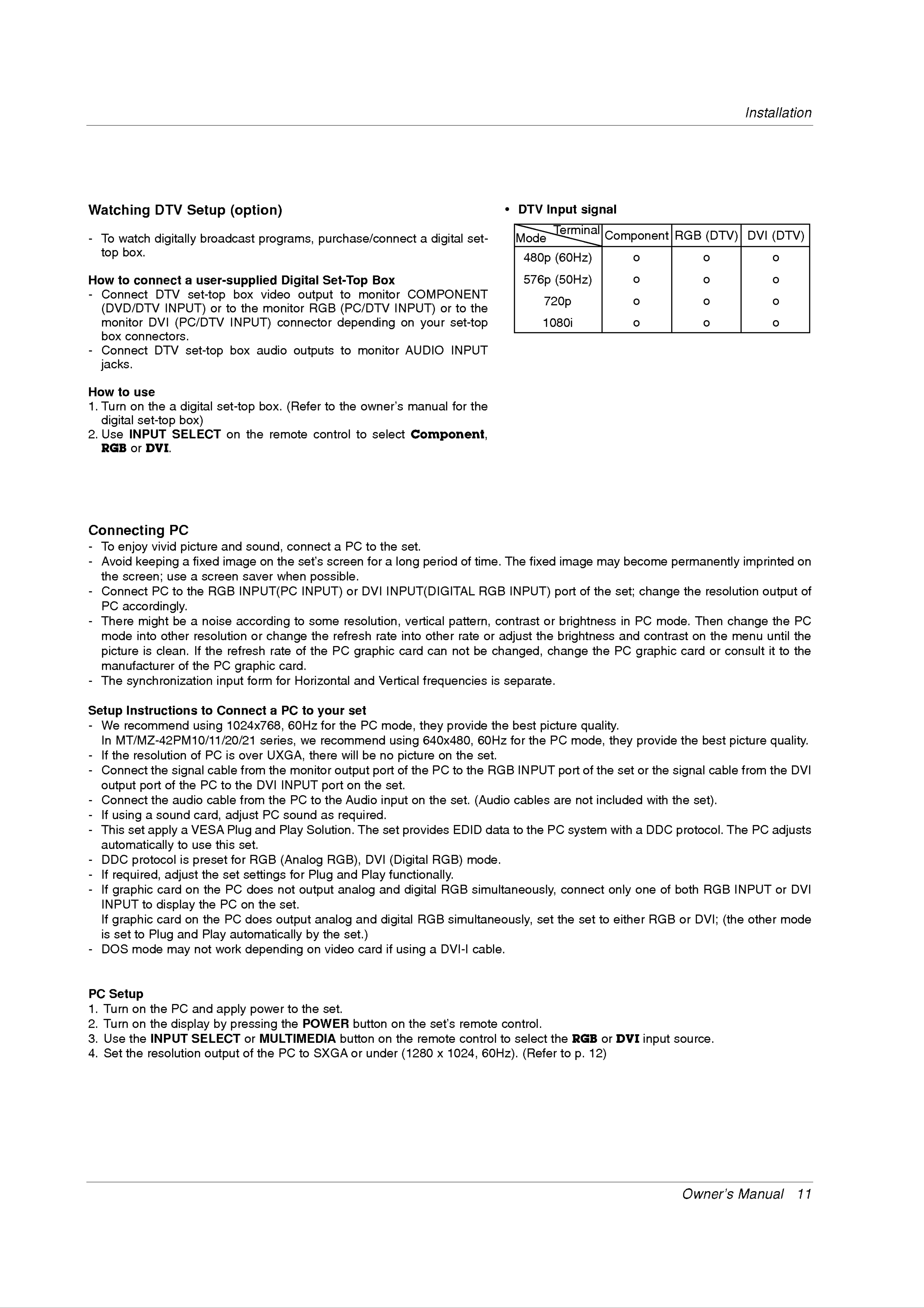
?
DTV
Mode
480p
576p
Input
Terminal
(60Hz)
(50Hz)
signal
Component
o
o
o
RGB
(DTV)
o
o
o
DVI
(DTV)
o
o
o
720p
-
How
1.
monitor
box
Connect
connectors.
jacks.
to
Turn
use
on
digital
DVI
DTV
the
a
set-top
(PC/DTV
set-top
digital
box)
INPUT)
box
set-top
audio
box.
connector
outputs
(Refer
to
depending
to
the
monitor
owner's
on
AUDIO
manual
your
set-top
INPUT
for
the
1080i
o
o
o
2.
Use
RGB
INPUT
or
DVI.
Connecting
SELECT
PC
on
the
remote
control
to
select
Component,
-
-
-
-
To
Avoid
the
Connect
PC
There
mode
enjoy
keeping
screen;
accordingly.
into
picture
vivid
PC
might
other
is
clean.
use
to
be
picture
a
fixed
a
screen saver
the
a
resolution
If
RGB
noise
the
and
image
INPUT(PC
according
refresh
sound,
on
or
change
rate
connect
the
when
set's
possible.
INPUT)
to
of
some
the
the
a
screen
PC
or
resolution,
refresh
PC
to
for
DVI
the
a
INPUT(DIGITAL
rate
graphic
set.
long
vertical
into
card
period
pattern,
other
can
not
of
rate
time.
RGB
or
be
changed,
The
INPUT)
contrast
adjust
fixed
or
the
change
image
port
of
may
the
brightness
brightness
the
become
set;
in
and
PC
permanently
change
PC
contrast
mode.
graphic
the
Then
on
card
imprinted
resolution
change
the
or
menu
consult
output
the
until
it
to
on
of
PC
the
the
manufacturer
-
The
Setup
-
-
-
We
In
If
the
Connect
of
the
synchronization
Instructions
recommend
MT/MZ-42PM10/11/20/21
resolution
the
signal
to
using
of
PC
PC
input
Connect
1024x768,
is
cable
graphic
form
a
series,
over
from
UXGA,
the
card.
for
PC
60Hz
monitor
Horizontal
to
we
your
for
recommend
there
output
set
the
will
and
PC
be
Vertical
mode,
using
no
port
picture
of
frequencies
they
the
provide
640x480,
on
PC
the
to
the
is
the
60Hz
set.
RGB
separate.
best
for
INPUT
the
picture
PC
port
quality.
mode,
of
the
they
set
provide
or
the
signal
the
best
cable
picture
from
quality.
the
DVI
output
-
-
-
Connect
If
using
This
set
port
the
a
apply
of
sound
automatically
-
-
-
DDC
If
required,
If
graphic
protocol
adjust
card
the
audio
a
VESA
to
is
on
PC
cable
to
card,
use
this
preset
the
the
the
from
adjust
Plug
set.
for
set
PC
RGB
settings
does
DVI
PC
and
the
not
INPUT
PC
sound
Play
to
Solution.
(Analog
for
Plug
output
port
the
as
required.
RGB),
and
analog
on
Audio
the
The
Play
DVI
set.
input
set
on
provides
(Digital
the
RGB)
functionally.
and
digital
RGB
set.
EDID
(Audio
data
mode.
cables
to
the
simultaneously,
PC
are
system
connect
not
included
with
only
a
one
with
DDC
of
the
set).
protocol.
both
RGB
The
INPUT
PC
adjusts
or
DVI
-
PC
1.
INPUT
If
graphic
is
DOS
set
Setup
Turn
to
to
mode
on
display
card
Plug
the
and
may
PC
on
the
not
and
PC
the
Play
work
apply
PC
on
does
the
set.
output
automatically
depending
power
to
by
on
the
analog
the
video
set.
set.)
and
card
digital
if
using
RGB
a
simultaneously,
DVI-I
cable.
set
the
set
to
either
RGB
or
DVI;
(the
other
mode
2.
3.
4.
Turn
Use
Set
on
the
the
the
INPUT
resolution
display
by
SELECT
output
pressing
or
of
MULTIMEDIA
the
the
PC
POWER
to
SXGA
button
button
or
on
under
on
the
(1280
the
remote
set's
x
1024,
remote
control
60Hz).
control.
to
select
(Refer
the
to
RGB
p.
or
12)
DVI
input
source.
Owner's
Manual
11
 Loading...