

LG MZ-42PZ14, MZ-42PZ12, MT-42PZ14, MT-42PZ14B, MZ-42PZ14B Service Manual
...
PLASMA MONITOR
SERVICE MANUAL
CAUTION
BEFORE SERVICING THE CHASSIS,
READ THE SAFETY PRECAUTIONS IN THIS MANUAL.
CHASSIS : MP-00MC
MODEL : MT/MZ-42PZ12/B
MODEL : MT/MZ-42PZ14/B
MODEL : MT/MZ-42PZ24/B
website:http://biz.LGservice.com
e-mail:http://www.LGEservice.com/techsup.html
March,2002
Printed in KoreaP/NO : 3828VD0113P

- 2 -
CONTENTS
Contents ................................................................................................................. 2
Safety Precautions ............................................................................................3
Specifications ..................................................................................................... 4
Control Descriptions ........................................................................................ 5
Adjustment Instructions ............................................................................... 8
Block Diagram .................................................................................................... 12
Exploded View ............................................................................................ 14,16
Exploded View Parts List.........................................................................15,17
Replacement Parts List ................................................................................ 18
SVC. Sheet ................................................................................................................
- 3 -
SAFETY PRECAUTIONS
Many electrical and mechanical parts in this chassis have special safety-related characteristics. These parts are identified by in
the Schematic Diagram and Replacement Parts List.
It is essential that these special safety parts should be replaced with the same components as recommended in this manual to
prevent X-RADIATION, Shock, Fire, or other Hazards.
Do not modify the original design without permission of manufacturer.
General Guidance
An lsolation Transformer should always be used during
the servicing of a receiver whose chassis is not isolated from
the AC power line. Use a transformer of adequate power rating
as this protects the technician from accidents resulting in
personal injury from electrical shocks.
It will also protect the receiver and it's components from being
damaged by accidental shorts of the circuitary that may be
inadvertently introduced during the service operation.
If any fuse (or Fusible Resistor) in this monitor is blown, replace
it with the specified.
When replacing a high wattage resistor (Oxide Metal Film
Resistor, over 1W), keep the resistor 10mm away from PCB.
Keep wires away from high voltage or high temperature parts.
Due to high vacuum and large surface area of picture tube,
extreme care should be used in handling the Picture Tube.
Do not lift the Picture tube by it's Neck.
Leakage Current Cold Check(Antenna Cold Check)
With the instrument AC plug removed from AC source,
connect an electrical jumper across the two AC plug prongs.
Place the AC switch in the on positioin, connect one lead of
ohm-meter to the AC plug prongs tied together and touch other
ohm-meter lead in turn to each exposed metallic parts such as
antenna terminals, phone jacks, etc.
If the exposed metallic part has a return path to the chassis, the
measured resistance should be between 1MΩ and 5.2MΩ.
When the exposed metal has no return path to the chassis the
reading must be infinite.
An other abnormality exists that must be corrected before the
receiver is returned to the customer.
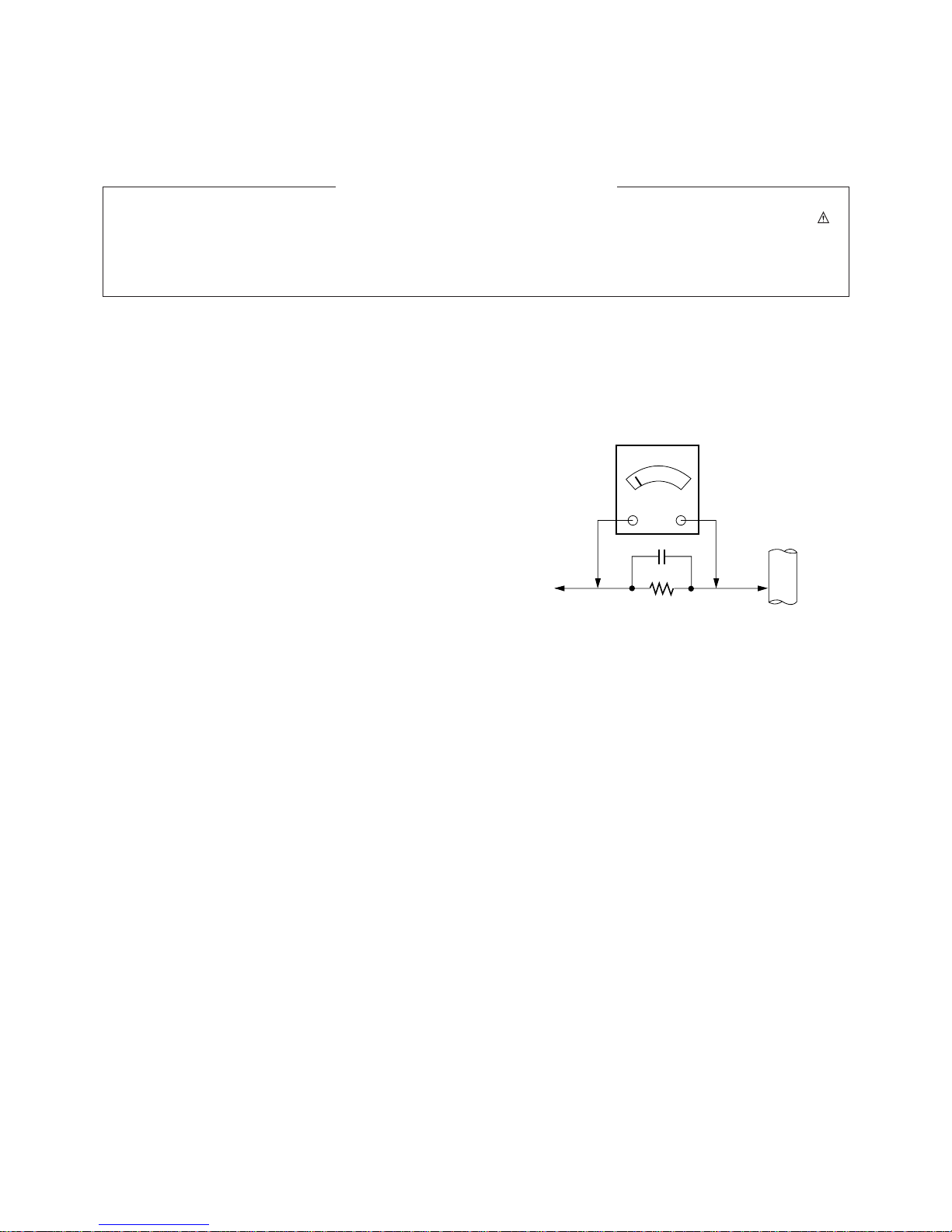
Leakage Current Hot Check (See below Figure)
Plug the AC cord directly into the AC outlet.
Do not use a line Isolation Transformer during this check.
Connect 1.5K/10watt resistor in parallel with a 0.15uF capacitor
between a known good earth ground (Water Pipe, Conduit, etc.)
and the exposed metallic parts.
Measure the AC voltage across the resistor using AC
voltmeter with 1000 ohms/volt or more sensitivity.
Reverse plug the AC cord into the AC outlet and repeat AC
voltage measurements for each esposed metallic part. Any
voltage measured must not exceed 0.75 volt RMS which is
corresponds to 0.5mA.
In case any measurement is out of the limits sepcified, there is
possibility of shock hazard and the set must be checked and
repaired before it is returned to the customer.
Leakage Current Hot Check circuit
1.5 Kohm/10W
To Instrument's
exposed
METALLIC PARTS
Good Earth Ground
such as WATER PIPE,
CONDUIT etc.
AC Volt-meter
IMPORTANT SAFETY NOTICE
0.15uF
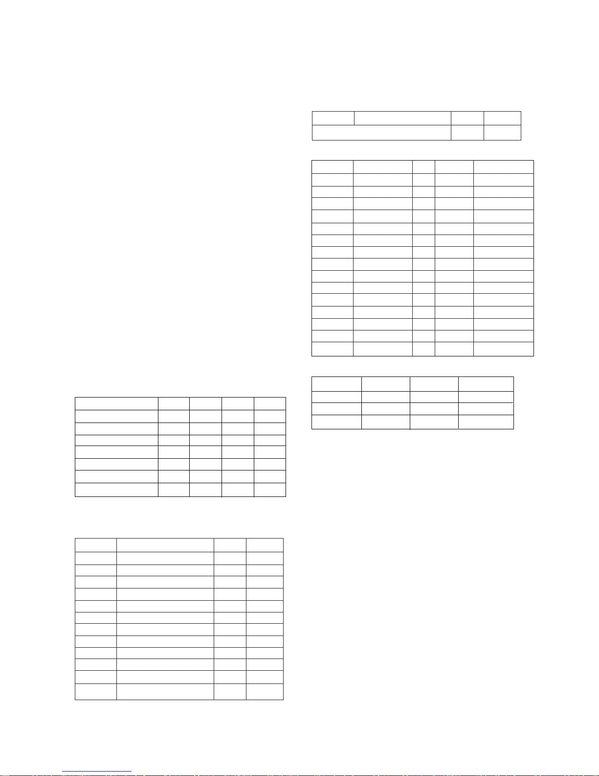
SPECIFICATIONS
Note : Specification and others are subject to change without notice for improvement.
O MONITOR
O Video receiving system:
PAL/SECAM/NTSC
VGA
SVGA
O Input Voltage : AC 200~240V, 50/60Hz(MZ-)
O Input Voltage : AC 110~240V, 50/60Hz(MT-)
O Power consumption : Max 400W
Stand-By : 5W
O PDP Module : PDP42WVSN3
O Speaker Impedance : 8 ohm
O Sound output : 10W max
O Feature : AV Input (Bottom)
Component Input (Bottom)
RGB Input (Bottom,D-Sub 15pin)
External SPK Out (Bottom,SPK Jack)
O Funtion : PSM /SSM/Child Lock
O External Interface
AV/COMPONENT Output
RGB/HV Control Signal In/Out Spec(
D-sub 25 pin Cable:PDP TV only)
O SET TOP BOX
O Video receiving system:
PAL-BG/DK/I
SECAM LL’
O Input Voltage : AC 110~240V, 50/60Hz
O Tuning System : FVS 100 Program
O Power consumption : Max 35W
Stand-By : 2W
O Available Channel : VHF : E2~E12(L/L’:B,C,D)
UHF : E21~E69
CATV : S1~S20(HYPER:S21~S41)
O Feature : AV In/out(Full Scart) : AV1(With RGB in/TV out)
AV In/out(Half Scart) : AV2(Monitor out)
V(Rear,CVBS)
S-Input
Y,Pb,Pr Input : Component(Rear,480I,480P)
RGB Input : RGB-PC(Rear,D-Sub 15pin)
Audio-Input : Component/RGB- PC
RGB out : RGB-PC(Rear,D-Sub 15pin)
RGB out/Control :
PDP MNT connection:RGB,Control
Woofer out :
Woofer Speaker
INPUT 25pin SPEC
Component Mode(Y,CB/PB,CR/PR)
- 4 -
ITEM
AV Video in
AV SYNC in
AV Burst in
AV Video in,L/R
AV Audio in,L/R
Component Video in
RGB/HV in
MIN
0.85
0.24
0.14
0.47
0.47
0.6
0.6
TYP
1.00
0.29
0.28
0.63
0.63
0.7
0.7
MAX
1.15
0.32
0.35
0.79
0.79
0.8
0.8
UNIT
Vpp
Vppz
Vpp
V
V
Vpp
Vpp
Resolution
640*480
640*480
704*480
H-Freq(Khz)
15.73
15.63
31.47
V-Freq(hz)
60
50
59.94
Proposed
SDTV,DVD 480I
SDTV,DVD 480I
SDTV 480P
PIn Name
R
G
B
GND
GND
GND
GND
GND
GND
GND
GND
GND
H Sync
V Sync
GND
Spec.
0.7Vpp
¡ 0.05
0.7Vpp¡ 0.05
0.7Vpp¡ 0.05
NC
Case Comon GND
R-return(shield)
G-return(shield)
B-return(shield)
NC
Case Comon GND
Case Comon GND
NC
4.0Vpp¡ 0.5
3.0Vpp¡ 0.5
NC
Pin
GND
STB-SDA
GND
STB-SCL
GND
GND
VSC-DET
GND
STB-DET
Spec.
Case Comon GND
SDA:3.0~4.5Vpp
Case Comon GND
SCL:3.0~4.5Vpp
NC
NC
NC
NC
High(STB)/Low
No.
1
2
3
4
5
6
7
8
9
Output 15-9 pin Spec
PIn Name
R
G
B
GND
H.Sync
V.Sync
STB-DET
STB-SDA
STB-SCL
HDSTBDET
VSCPWRON
PWR-KEY
Spec.
0.7Vpp¡ 0.05
0.7Vpp¡ 0.05
0.7Vpp¡ 0.05
Case Common
4.0Vpp¡ 0.5
3.0Vpp¡ 0.5
High(STB)/Low
3.0~4.5Vpp
3.0~4.5Vpp
NC
NC
NC
Pin
VSC-Det
GND
GND
GND
GND
GND
GND
GND
GND
GND
GND
GND
No.
13
14
15
16
17
18
19
20
21
22
23
24
PIn Name
Spec.
Pin
GND
No.
25
Length:3m(-20,+50Cm,Audio(R/L):150
±10mm
- 5 -
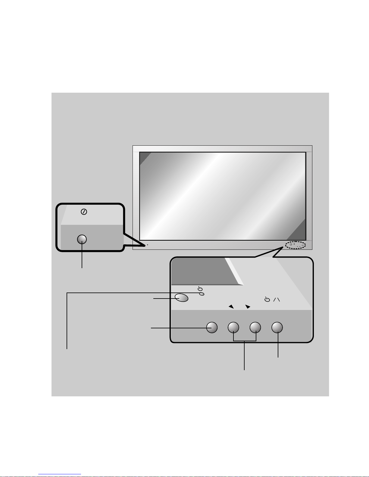
CONTROLS DESCRIPTION
ON/OFF
INPUT VOLUME
SELECT
ON/OFF
VOLUME
INPUT
SELECT
<Front Panel>
MAIN POWER BUTTON
INPUT SELECT BUTTON
REMOTE CONTROL SENSOR
POWER/STANDBY INDICATOR
Illuminates red in standby
Illuminates green when the Monitor is switched on
POWER BUTTON
VOLUME (FF,GG) BUTTON
- 6 -
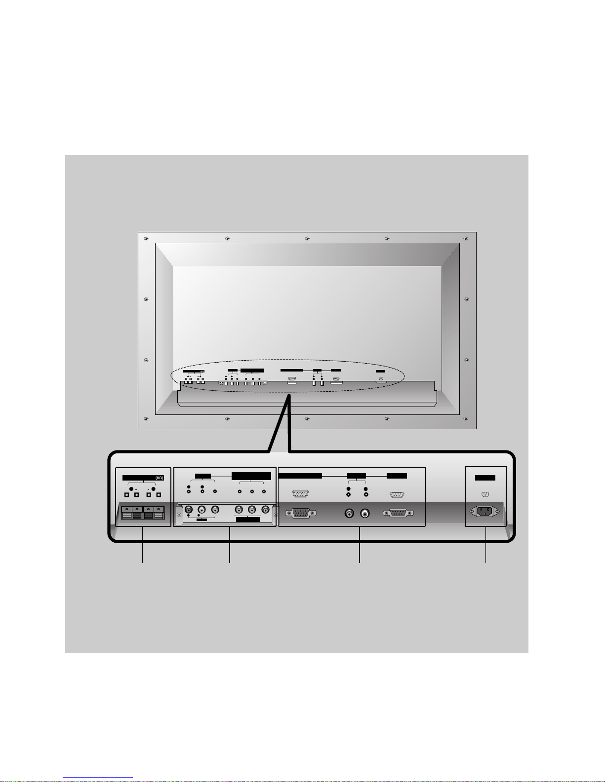
AC INPUT
RGB INPUT(VGA/SVGA/XGA)
(+) ( ) (+)( )
EXTERNAL SPEAKER
R L
R
AUDIO INPUT
CONTROL
L
(+) ( ) (+)( )
AC INPUT
EXTERNAL SPEAKER
R L R
AUDIO INPUT
CONTROL
L
RGB INPUT(VGA/SVGA/XGA)
P
B R
Y P
AV INPUT
R L
AUDIO
<MONO>
VIDEO
COMPONENT (480i/480p)
(DVD INPUT)
PBY
R
P
AV INPUT
(DVD INPUT)
COMPONENT (480i/480p)
R L
AUDIO VIDEO
(MONO)
PBY
R
P
R L
AUDIO VIDEO
(MONO)
AV INPUT
(DVD INPUT)
COMPONENT (480i/480p)
<Back Panel>
EXTERNAL
SPEAKER (8Ω)
KNOBS
AV INPUT /
COMPONENT (480i/480p)
DVD INPUT SOCKETS
RGB INPUT (VGA/SVGA/XGA) /
AUDIO INPUT / CONTROL
SOCKET
POWER INPUT
SOCKET
This Monitor operates
on an AC mains supply,
the voltage is as indicated as inside back cover
of this manual. Never
apply DC power to the
Monitor.
- 7 -
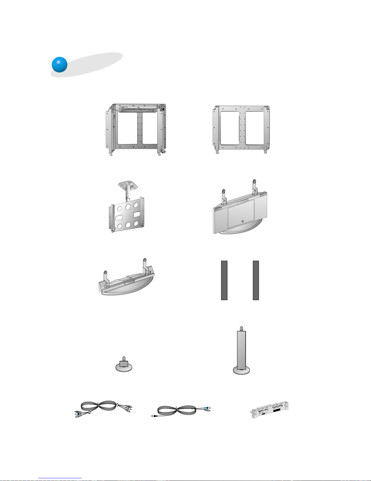
Optional Extras
AP-42WA20M series
(Tilt wall mounting bracket)
AP-42WA10 series
(Wall mounting bracket)
AP-42CA10 series
(Ceiling mounting bracket)
AP-42FA10 series
(Floor type stand)
AP-42DA10 series
(Desktop stand)
AP-42SA10 series
(Speakers)
AP-42SA10D series
(Speaker stand)
AP-42SA10F series
(Floor type speaker stand)
Video cables
Audio cables
P
B
Y
R
P
R L
AUDIO VIDEO
(MONO)
AV INPUT
(DVD INPUT)
COMPONENT (480i/480p)
AP-42EA20 (Interface board)
- Optional extras can be changed or modified for quality improvement without any notification new
optional extras can be added.
- Contract your dealer for buying these items.
- 8 -
1. Application Object
These instructions are applied to all of the PDP monitor, MP00MC.
2. Notes
(1) Because this is not a hot chassis, it is not necessary to use
an isolation transformer. However, the use of isolation
transformer will help protect test instrument.
(2) Adjustment must be done in the correct order.
(3) The adjustment must be performed in the circumstance of
20±5°C of temperature and 65±10% of relative humidity if
there is no specific designation.
(4) The input voltage of the receiver must keep 110/240V,
50/60Hz in adjusting.
(5) The receiver must be operated for about 15 minutes prior
to the adjustment.
1) After receiving 100% white pattern, the receiver must be
operate prior to adjustment.(Or white condition in HEATRUN mode)
2) Enter into HEAT-RUN mode
- Select the HEAT-RUN OFF by pressing SVC button
on Remote Control for adjustment.
- Press the VOL + button in HEAT-RUN OFF.
(OSD display HEAT-RUN WHITE and screen display
100% full WHITE PATTERN)
3) Set is activated HEAT-RUN without SET TOP BOX or
signal generator in this mode.
[ Single color pattern of HEAT-RUN mode uses to check
PANEL.(RED/BLUE/GREEN)
[Caution] If you turn on a still screen more than 20 minutes, a
afterinage may be occur in the black level part of the
screen.
3. POWER PCB Assy Voltage Adjustment
[ Replace PDP Module or Power Board, adjust certainly Power
PCB Assy Voltage.
3-1. Test Equipment
D.M.M 1EA
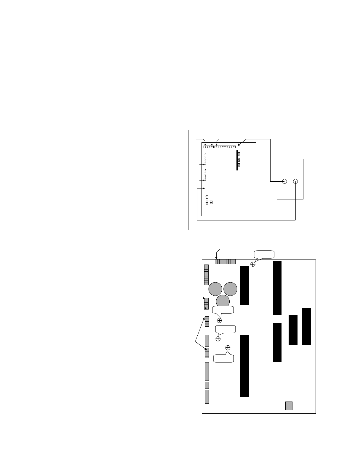
3-2. Connection Diagram for Measuring
Refer to Fig 1.
3-3. Adjustment Method
(1) Va Adjustment(Address Voltage Adjustment)
1) Connect pin 1 of P806 or P811 to (+) jack of D.M.M.
2) After turning the VR351(Va Adj), voltage of D.M.M
adjustment as same as Va voltage which on label of
panel right/bottom.(Deviation : ±0.5V)
(2) Vs Adjustment
1) Connect pin 9 of P803 to (+) jack of D.M.M.
2) After turning the VR551(Vs Adj), voltage of D.M.M adjust
as same as Vs voltage which indicated on label of panel
right/bottom.(Deviation : ±0.5V)
(3) VSC Adjustment
1) Connect pin 4 of P802 to (+) jack of D.M.M.
2) After turning the VR751(VSC Adj), voltage of D.M.M
adjust as same as Vs voltage which indicated on label
of panel right/bottom.(Deviation : ±0.5V)
(4) VSETUP Adjustment
1) Connect pin 1 of P802 to (+) jack of D.M.M.
2) After turning the VR651(VSETUP Adj),voltage of D.M.M
adjust as same as Vs voltage which indicated on label
of panel right/bottom.(Deviation : ±0.5V)
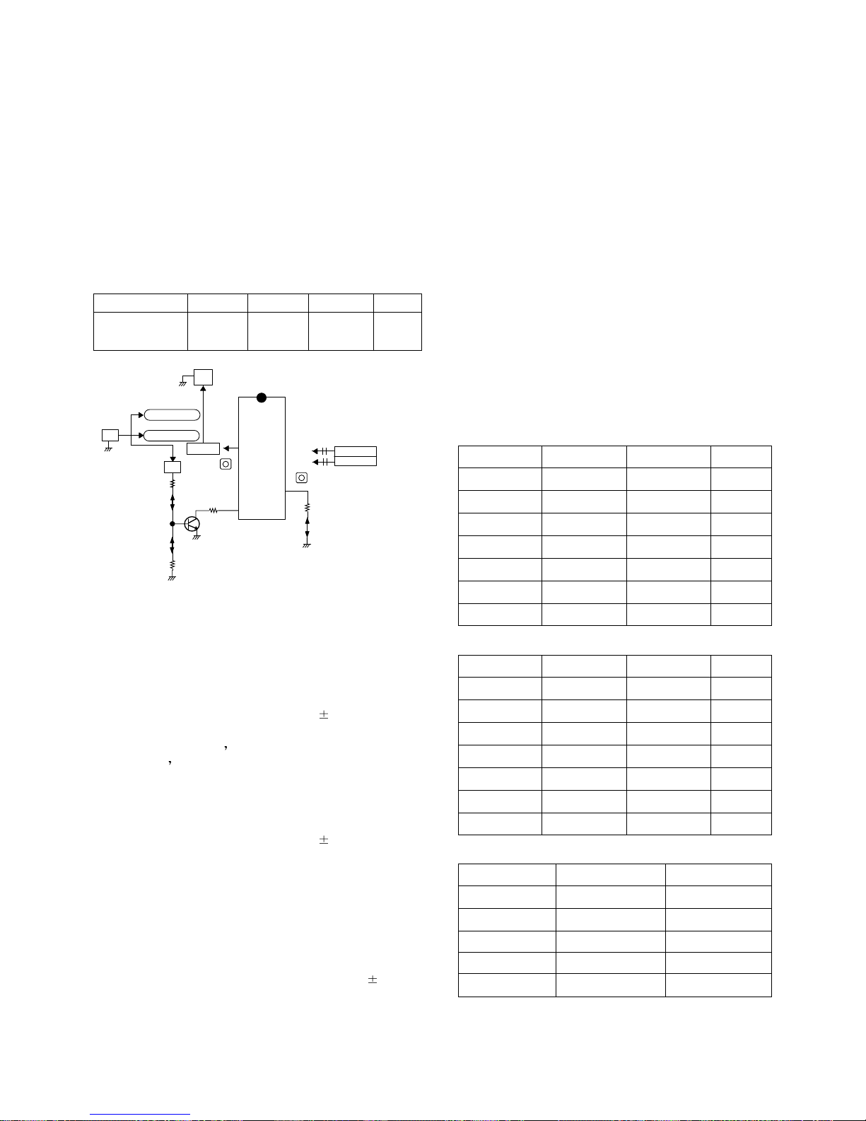
ADJUSTMENT INSTRUCTIONS
Vy
VR551
VR651
VR751
DMM
VSET UP
VA
VA
VS CTL
V
A CTL
VR351
GND
V
SETUP CTL
V
y CTL
V
S
<Fig 1> Connection Diagram of Power Adjustment for Measuring
- Vy
Vsetup
Vs
Va
Vsetup ADJ
VR8104
Va ADJ
VR8105
Vs ADJ
VR8102
- Vy ADJ
VR8103
<Fig 1> Connection Diagram of POWERWEL Power Adj. for Measuring
- 9 -
4. Adjustment of RGB Cut-off and
White Balance
4-1. Required Equipment
Color analyzer(CA-100 or same production)
4-2. Connection Diagram of Equipment for
Measuring
4-3. Adjustment of RGB CUT OFF
(1) Select A/C SRT (cut-off automatic adjustment ) by
pressing SVC button on Remote Control for adjustment.
(2) Press the VOL + or VOL - button.
(3) It displayed all of the black on the screen and then
adjustment is started.
(4) If adjustment is finished, exit from adjustment mode by
pressing A/V button.
4-4. Adjustment of White Balance
• White Balance should be done after RGB cut-off become
adjustment.
• Operate the Zero-calibration of the CA—100, then stick
sensor to PDP module surface when you adjust.
(1) Select WHITE PATTERN of HEAT RUN mode by pressing
SVC button on Remote Control for adjustment then
operate HEAT RUN more than 15 minute.
(2) Supply window Signal in pattern generater.
[ When adjustment is operated manually, operate process (3)
to (6) regular sequence, when adjustment is operated
automatically operate process (1)~(2).
(3) To adjust Low Light, stick sensor to pattern(Dark), select
the R cut/B cuby pressing SVC button on Remote Control
for adjustment and adjust it until color coordination
becomes X=0.280±0.003, Y=0.310±0.003 and color
temperature becomes 8.800
cK ± 500cK by pressing VOL+,
- button. (G-cut fixation)
(4) To adjust High Light, stick sensor to pattern(White).
Select the R Gain/G Gain(adjustment 6) by pressing SVC
button on Remote Control for adjustment and adjust R
Gain/G Gain until color coordination becomes
X=0.280±0.003, Y=0.310±0.003 and color temperature
becomes 8.800cK ± 500cK.(B-Gain fixation)
(5) Confirm the result of the High Light adjustment.
If the deviation of High Light occur, operate the adjustment
of Low Light and High Light again.
(6) Exit adjustment mode using AV button.
5. Color Temperature of STB
White Balance Adjustment
5-1. Required Equipment
Color Analyzer(CA-110, CA-100 or same production)
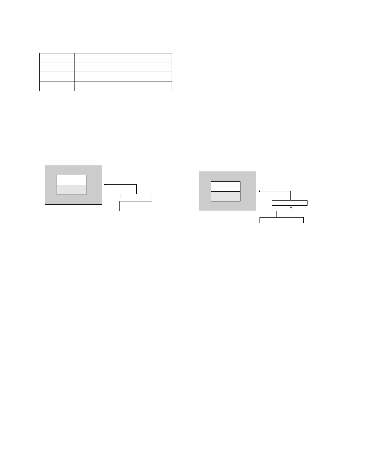
5-2. Connection diagram of equipment for
measuring
(1) To adjust the deviation of the STB signal output.
(2) Use regular PDP Monitor(JIG).
5-3. Adjustment Method
• Connect the STB to regular PDP Monitor.
• Operate the zero-calibration of the CA-100, then stick
sensor to surface of PDP module when you adjust.
(1) Select WHITE PATTERN of HEAT RUN mode by pressing
SVC button on Remote Control for adjustment, then
operate HEAT RUN more than 15 minute.
(Operate the HEAT RUN to adjust the STB at first, then if
OFF hour don’t keep more than 3 minutes, operate next
adjustment of the STB without HEAT RUN.)
(2) Supply window Signal to RZ-BA10 in pattern generator.
[ When adjustment is operated manually, operate process (3)
to (7) regular sequence, when adjustment is operated
automatically operate process (1) to (2).
(3) Select STB CXA2101 by pressing SVC,ADJUST button on
Remote Control for adjustment.
(4) To adjust Low Light, stick sensor to 9th pattern(Dark).
Select the B Cut/R Cut, then adjust the B Cut/R Cut until
color coordination becomes X=0.280±0.003,
Y=0.310±0.003 and color temperature becomes 8.800cK
± 500cK by pressing VOL+, - button. (Adjust in B Cut
10±1, R Cut 6±1)
(5) To adjust High Light, stick sensor to 2th pattern(White).
Select the R Gain/G Gain, then adjust the R Gain/G Gain
until color coordination becomes X=0.280±0.003,
Y=0.310±0.003 and color temperature becomes 8.800cK
± 500cK. (B-Gain fixation)
(6) Confirm the result of the High Light adjustment.
COLOR
ANALYZER
TYPE; CA-100
CVBS Signal Input
PDP MONITOR
RZ-BA10(STB)
Window Pattern
MSPG-2100 or MSTG-5200
High Light
90±5cd/m2
Low Light
6±1cd/m2
<Fig 3> Connection Diagram of STB Automatic Adjustment
COLOR
ANALYZER
TYPE; CA-100
Window Pattern
CVBS Signal Input
High Light
90±5cd/m2
Low Light
6±1cd/m2
PDP MONITOR
MSPG-2100 or
MSTG-5200
<Fig 2> Connection Diagram of Automatic Adjustment
Refer to Typical Voltage
Va
Vs
Vy
Vsetup
60 ~ 75V
170 ~ 185V
-60 ~ -90V
210 ~ 240V
If the deviation of High Light occur, operate the adjustment
of Low Light and High Light again.
(Expectation average adjustment data : B-Cut & RCut=6±2, R-Gain/G-Gain=25±3)
(7) Exit adjustment mode using A/V button.
6. Adjustment of AFT-VCO COIL
6-1. Preparation for Adjustment
(1) Connect the equipment for measuring as below.
(2) Setting equipment for measuring.
RF Signal generator
* Output of Power Supply = DC 5V
* Oscilloscope range = set 0.5V/div., 5msec/Div.(using scope)
6-2. Adjustment 38.9MHz IF(B/G, D/K, I, L, M)
(1) Input the signal of the signal generater(38.9MHz) to
TP105(IC102 pin 7) through 0.01uF(103) capacitor.
(2) S1 : OFF, S2 : ON, S3 : OFF
(3) Adjust voltage of the TP103 to 2.5
0.1V by adjusting
X106.
6-3 Adjustment L VCO(Adjustment
SECAM-L ) --> Only SECAM L model
(1) After changing the signal of the signal generater to
34.25MHz, input the signal to TP102(IC102 pin 11) through
0.01uF(103) capacitor.
(2) S1 : ON, S2 : OFF, S3 : ON
(3) Adjust voltage of the TP103 to 2.5
0.1V by adjusting
VR101.
7. Adjustment AGC
7-1 Preparation for Adjustment
(1) Connect the signal of PAL-B/G 05ch. to Antenna jack.
(2) Connect Multi meter to point(J150) of AGC adjustment.
7-2 Adjustment
Adjustment the voltage of Multi meter to 2.4 0.1V by
changing VR102.
8. OPTION TABLE
8-1 Funtion of Line Service
(1) • Enter to SVC mode by using SVC button on the remote
control.
•To enter to the SVC mode,press the “OK” button on RZBA10 local key ond “OK” button on the remote control
simultaneously.
• In MZ-42PZ10 only,press the “INPUT” button and “OK”
button on remote control to enter to SVC mode.
(2) Select the item by using the Quick View(Yellow) button.
(3) After adjusting,restore adjusted item in EEPROM by using
“OK” button and use the CYAN button to cancel the
adjusted condition.
(4) Select the program directly and input the data of option by
using the number button.
(5) Line SVC-0(Hitrun&W/B Adj.mode)=> VSC EEPROM
• H/T RUN:OFF,WHITE,RED,GREEN,BLUE,OFF
• A/C SRT:Auto Cutoff
• R/G/B Fine 16,R/G/B Gain 3,R/G/B Cutoff 100
(6) Line SVC-1(Phase&Position Adj.mode)=> VSC EEPROM
• Phase 15,H-Pos 32,V-Pos 32,Auto Position
(7) VSC CXA2101 Adj.mode)=> VSC EEPROM
(8) STB CXA2101 Adj.mode)=> STB EEPROM
(9) SOUND Adj.mode => VSC EEPROM
- 10 -
IC102
TDA4474
TP103
ST-BY 5V:P001
24
7
13
15
1
0.01uF
TP105
X106
(VCO)
5V
PowerSupply
V Multimeter or Oscilloscope
TP110
38.9MHz
34.25MHz
(B/G,D/K,I,L)
(SECAM-L')
100 ohm
S1
5V
4.7 Kohm
S3
Q110
VR101
16
TP112(IF VCC)
S2
TP111
100 ohm
11 TP102
VR102(AGC)
(STB MAIN)
BC 7
RC 7
RG 10
GG 10
BG 10
SUB-CON 3
SUB-BRI 49
SUB-COL 15
ST 7
SUB-SHP 1
CTI 0
RYR 6
GYR 10
RYB 9
GYB 5
GMM 5
BLK 15
PRE 1
DCT 1
DPI 2
VTC 2
HWI 2
DCO 1
HDT 0
SFO 1
BC 7
RC 7
RG 31
GG 31
BG 31
SUB-CON 3
SUB-BRI 50
SUB-COL 0
SUB-HUE 14
SUB-SHP 0
CTI 1
RYR 6
GYR 10
RYB 9
GYB 5
GMM 0
BLK 15
PRE 1
DCT 0
DPI 0
VTC 2
HWI 2
DCO 0
HDT 0
SFO 1
CON 23
BRI 31
COL 31
HUE 31
SHP 35
FP
NP
SP
SC VOL
TB VOL
MT-42PZ12
14
80
25
83
118
MZ-42PZ12
28
120
25
68
115
ADJ.Point
X106
VR101
System
B/G,D/K/I,SECAM-L
SECAM-L’
Frequency
38.9
34.25
Modulation
OFF
OFF
Level
80dBuV
80dBuV
 Loading...