

LG MT-42PM10, MT-42PM10B, MT-42PM10HB, MT-42PM11, MT-42PM11R Service Manual

PLASMA MONITOR
SERVICE MANUAL
CAUTION
BEFORE SERVICING THE CHASSIS,
READ THE SAFETY PRECAUTIONS IN THIS MANUAL.
CHASSIS : RF-04GA
MODEL : MT-42PM10/B/HB
MODEL : MT-42PM11/R
website:http://biz.LGservice.com
e-mail:http://www.LGEservice.com/techsup.html

- 2 -
CONTENTS
CONTENTS .............................................................................................................2
SAFETY PRECAUTIONS .......................................................................................3
ADJUSTMENT INSTRUCTIONS ............................................................................4
SPECIFICATIONS................................................................................................ 10
ADJUSTMENT INSTRUCTIONS ..........................................................................13
TROUBLE SHOOTING GUIDE.............................................................................15
BLOCK DIAGRAM................................................................................................26
EXPLODED VIEW.................................................................................................28
EXPLODED VIEW PARTS LIST ...........................................................................29
REPLACEMENT PARTS LIST..............................................................................30
SCHEMATIC DIAGRAM ...........................................................................................
PRINTED CIRCUIT BOARD .....................................................................................
- 3 -
SAFETY PRECAUTIONS
Many electrical and mechanical parts in this chassis have special safety-related characteristics. These parts are identified by in
the Schematic Diagram and Replacement Parts List.
It is essential that these special safety parts should be replaced with the same components as recommended in this manual to
prevent X-RADIATION, Shock, Fire, or other Hazards.
Do not modify the original design without permission of manufacturer.
General Guidance
An isolation Transformer should always be used during
the servicing of a receiver whose chassis is not isolated from
the AC power line. Use a transformer of adequate power rating
as this protects the technician from accidents resulting in
personal injury from electrical shocks.
It will also protect the receiver and it's components from being
damaged by accidental shorts of the circuitry that may be
inadvertently introduced during the service operation.
If any fuse (or Fusible Resistor) in this monitor is blown, replace
it with the specified.
When replacing a high wattage resistor (Oxide Metal Film
Resistor, over 1W), keep the resistor 10mm away from PCB.
Keep wires away from high voltage or high temperature parts.
Due to high vacuum and large surface area of picture tube,
extreme care should be used in handling the Picture Tube.
Do not lift the Picture tube by it's Neck.
Leakage Current Cold Check(Antenna Cold Check)
With the instrument AC plug removed from AC source,
connect an electrical jumper across the two AC plug prongs.
Place the AC switch in the on position, connect one lead of
ohm-meter to the AC plug prongs tied together and touch other
ohm-meter lead in turn to each exposed metallic parts such as
antenna terminals, phone jacks, etc.
If the exposed metallic part has a return path to the chassis, the
measured resistance should be between 1MΩ and 5.2MΩ.
When the exposed metal has no return path to the chassis the
reading must be infinite.
An other abnormality exists that must be corrected before the
receiver is returned to the customer.
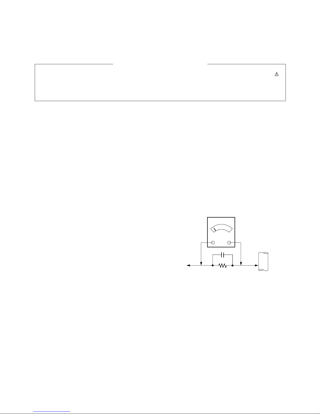
Leakage Current Hot Check (See below Figure)
Plug the AC cord directly into the AC outlet.
Do not use a line Isolation Transformer during this check.
Connect 1.5K/10watt resistor in parallel with a 0.15uF capacitor
between a known good earth ground (Water Pipe, Conduit, etc.)
and the exposed metallic parts.
Measure the AC voltage across the resistor using AC
voltmeter with 1000 ohms/volt or more sensitivity.
Reverse plug the AC cord into the AC outlet and repeat AC
voltage measurements for each exposed metallic part. Any
voltage measured must not exceed 0.75 volt RMS which is
corresponds to 0.5mA.
In case any measurement is out of the limits specified, there is
possibility of shock hazard and the set must be checked and
repaired before it is returned to the customer.
Leakage Current Hot Check circuit
1.5 Kohm/10W
To Instrument's
exposed
METALLIC PARTS
Good Earth Ground
such as WATER PIPE,
CONDUIT etc.
AC Volt-meter
IMPORTANT SAFETY NOTICE
0.15uF
DESCRIPTION OF CONTROLS
- 4 -
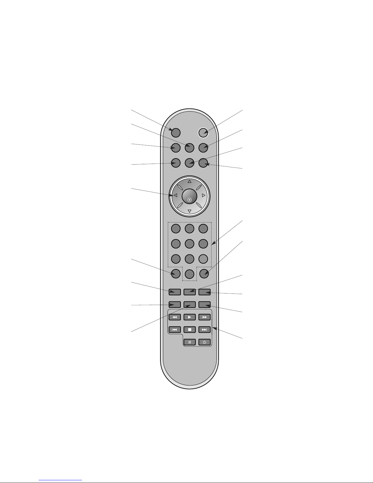
- When using the remote control aim it at the remote control sensor of the set.
- There's maybe a defect in consecutive operation of remote control in specified brightness according to this set feature.
POWERMUTE
PIP INPUT
MULTIMEDIA
EXIT ARC
MENU
VOL
OK
1 2 3
4 5 6
7
PSM
SSM
8 9
0
VOL
SPLIT ZOOM
PIP/DW
SLEEP
SCAN-
SKIP-
WIN. SIZE
SCAN+
PLAY
POSITION
SKIP+
STOP
SWAP
POWER
PAUSE
INPUT SELECT
MULTIMEDIA
Selects the Component, RGB or DVI
modes.
WIN.SIZE
Adjusts the sub picture size.
POWER
switches the set on from standby or
off to standby.
ARC
Changes the picture format.
MENU
Displays on screen menus one by
one.
Exits the current menu.
Memorizes menu changes.
SSM
To select the sound appropriate to
your viewing programme character.
NUMBER buttons
SLEEP
Sets the sleep timer.
PIP/DW
Switches the sub picture on or off.
Selects PIP or DW modes.
DVD BUTTONS
controls a LG DVD player.
SWAP
Alternates between main and sub picture.
INPUT SELECT
EXIT
Clears all on-screen displays.
PIP INPUT
Selects the input mode for the sub pic-
ture.
MUTE
Switches the sound on or off.
DD/ EE
Selects a menu option.
FF/ GG
(Volume Up/Down)
Increases/decreases sound level.
Adjusts menu settings.
OK
accepts your selection or displays the
current mode.
PSM
Adjusts the factory preset picture
according to the room.
SPLIT ZOOM
Enlarge the screen with regular
ration.
POSITION
Moves the sub picture to
DD/ EE
or FF/
GG
direction.
- 5 -
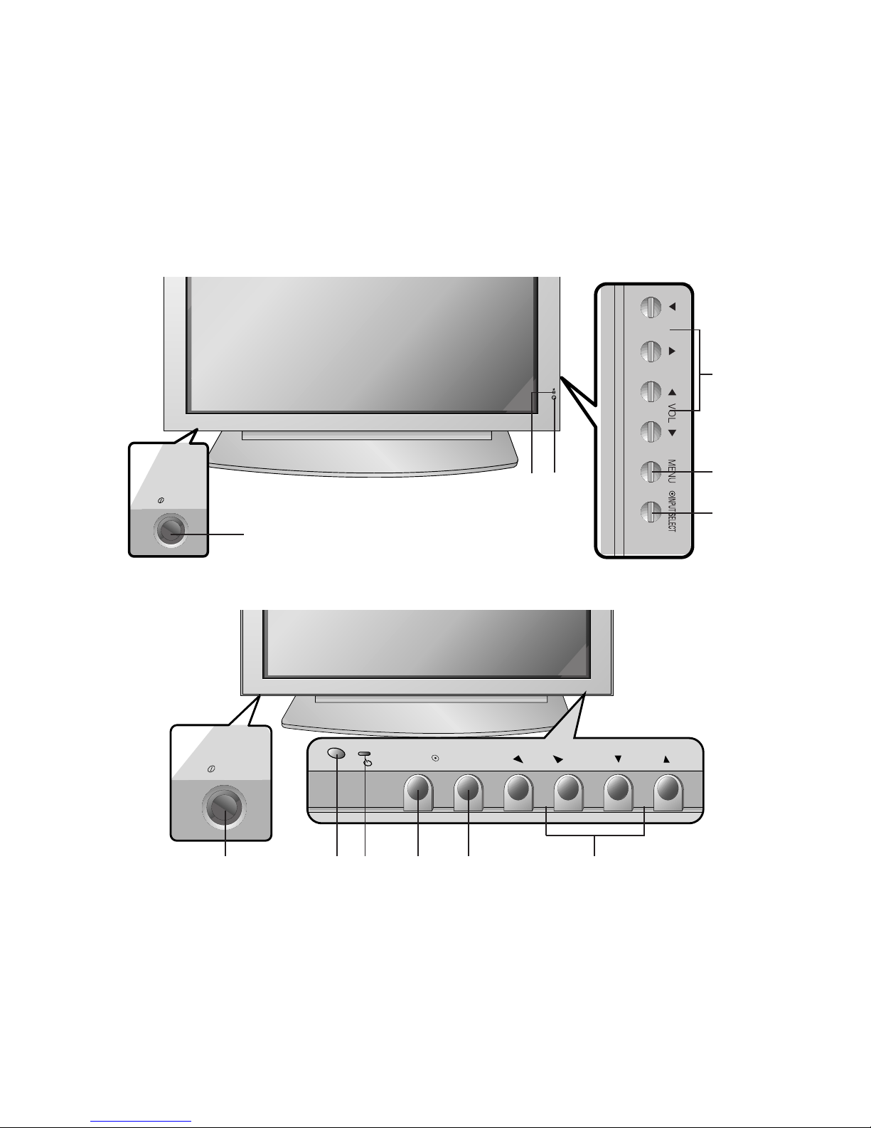
<Front Panel Controls>
MT/MZ-42/50PM10 series
MT/MZ-42/50PM20 series
ON/OFF
VOL
MENU
INPUT SELECT
ON/OFF
- Shown is a simplified representation of the set.
- Here shown may be somewhat different from your set.
1. Main Power Button
2. Remote Control Sensor
3. Power Standby Indicator
Illuminates red in standby mode, Illuminates green when the
set is turned on
4. INPUT SELECT Button
5. MENU
Displays on screen menus one by one.
Exits the current menu.
Memorizes menu changes.
6.
DD/ EE
Selects a menu option.
FF/ GG
(Volume Up/Down)
Increases/decreases sound level.
Adjusts menu settings.
1 2 3 4 5 6
1
4
5
6
2
3
- 6 -
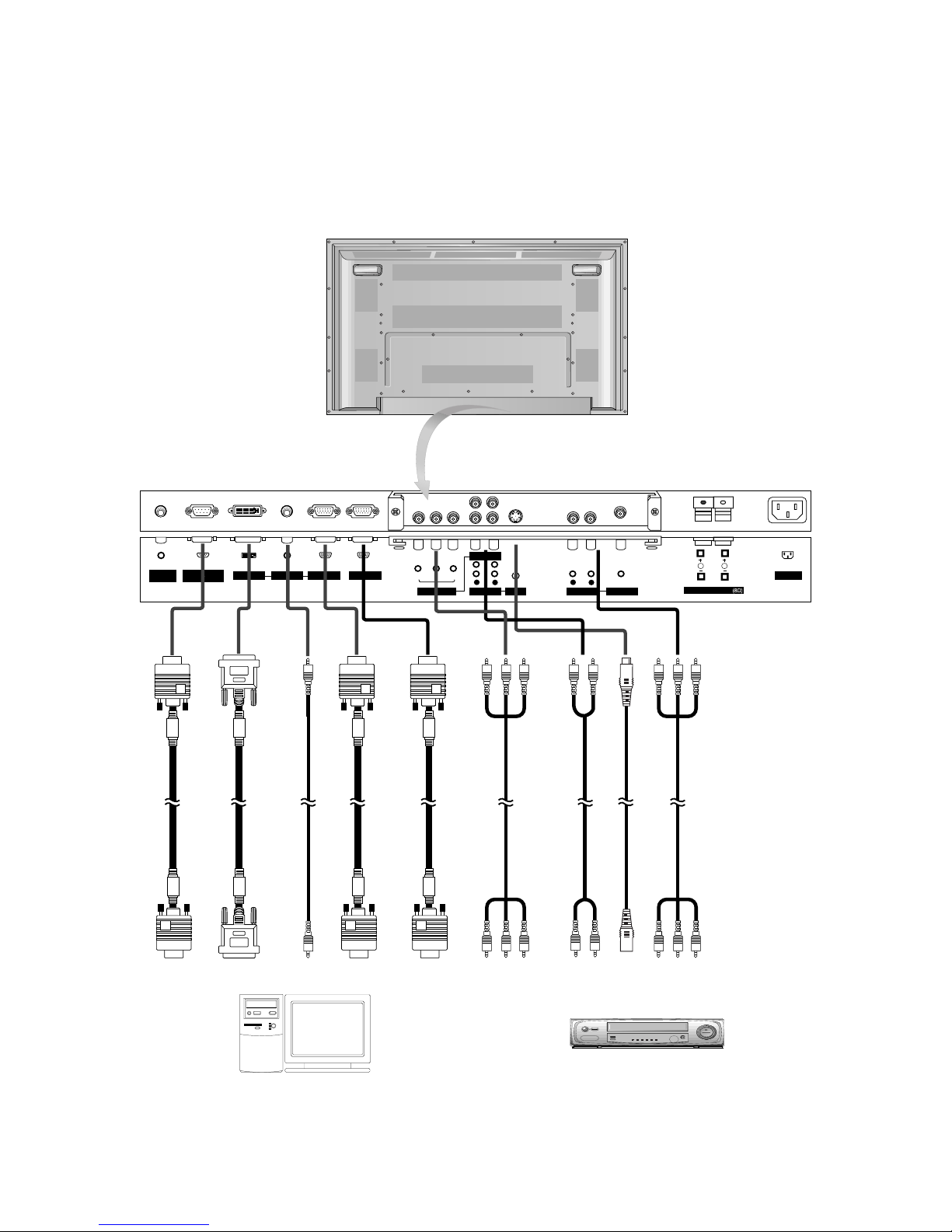
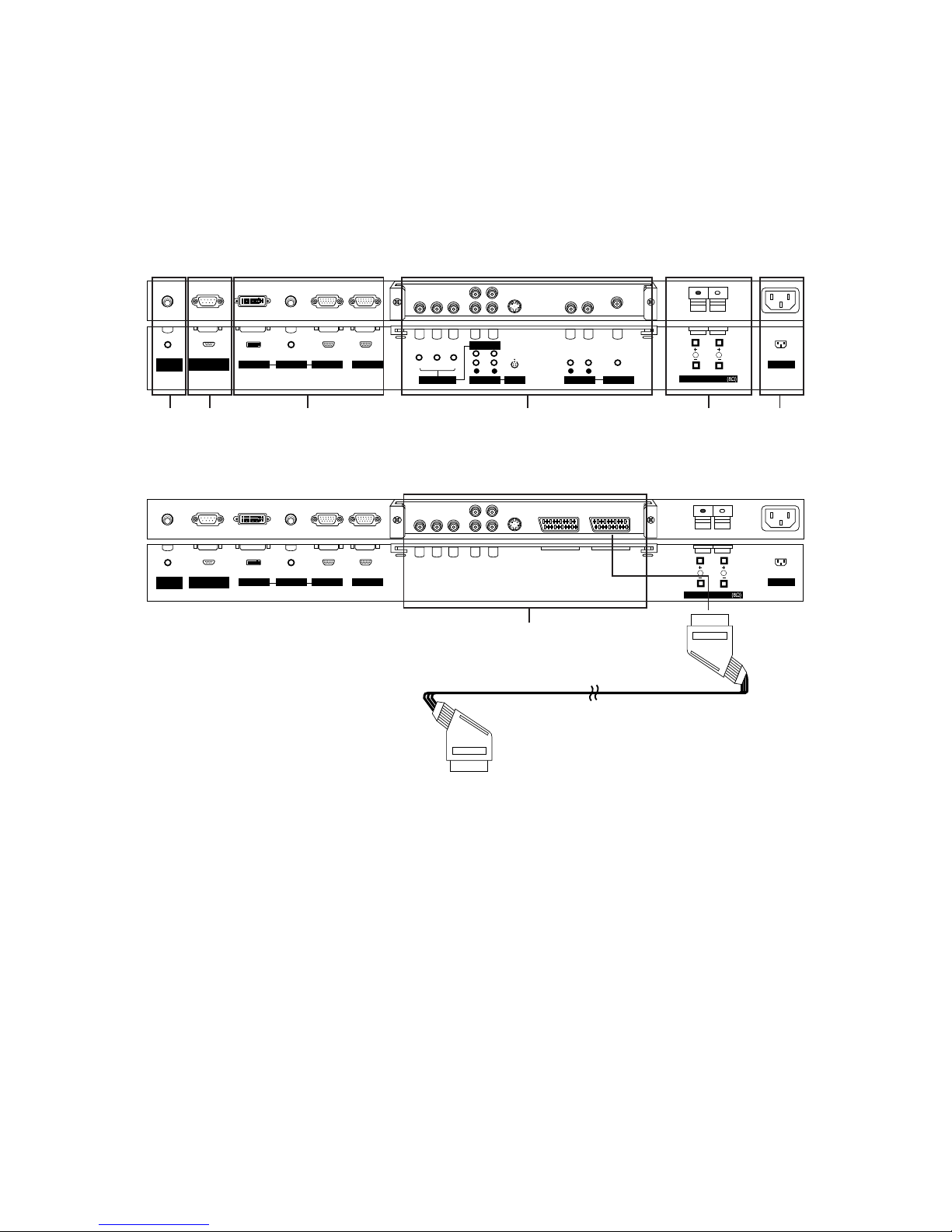
<Back Panel>
R
L
R
L
AC INPUT
AUDIO INPUT
AUDIO INPUT
AUDIO INPUT
VIDEO INPUT
AUDIO INPUT
S-VIDEO
RGB OUTPUTRGB INPUTDVI INPUT
RS-232C INPUT
(CONTROL/SERVICE)
REMOTE
CONTROL
YPBP
R
AUDIO (MONO)
COMPONENT INPUT
R
L
EXTERNAL SPEAKER
Connection to PC
Connection to AV equipment
- 7 -
<Back Panel>
AV1AV1
AC INPUT
AUDIO INPUT RGB OUTPUTRGB INPUTDVI INPUT
RS-232C INPUT
(CONTROL/SERVICE)
REMOTE
CONTROL
R
L
EXTERNAL SPEAKER
RCA Type
Scart Type
5
R
R
L
L
R
L
EXTERNAL SPEAKER
AC INPUT
AUDIO INPUT
AUDIO INPUT
AUDIO INPUT
VIDEO INPUT
AUDIO INPUT
S-VIDEO
RGB OUTPUTRGB INPUTDVI INPUT
RS-232C INPUT
(CONTROL/SERVICE)
REMOTE
CONTROL
Y PBP
R
AUDIO (MONO)
COMPONENT INPUT
1 2 3 645
1. CONTROL LOCK / REMOTE CONTROL
2. RS-232C INPUT(CONTROL/SERVICE) PORT
Connect to the RS-232C port on a PC.
3. DVI INPUT / AUDIO INPUT / RGB INPUT SOCKETS
Connect the monitor output socket of the PERSONAL COMPUTER to this socket.
RGB OUTPUT SOCKET
You can watch the RGB signal on another monitor, connect
RGB OUTPUT to another monitorÕs PC input port.
4. EXTERNAL SPEAKER OUTPUT (8 ohm)
Connect to optional external speaker(s).
*For further information, refer to ÔSpeaker & Speaker StandÕ
manual.
5. AUDIO / COMPONENT INPUT / S-VIDEO / VIDEO INPUT /
AUDIO INPUT SOCKETS
EURO SCART SOCKET
Note: The interface board (AP-42PM10/11) is not equipped
on MT/MZ-42PM10/12X/20 series / MT/MZ-50PM10/20
series models. Contact your dealer for buying this optional
item.
6. POWER CORD SOCKET
This Monitor operates on an AC power. The voltage is indicated on the Specifications page. Never attempt to operate
the Monitor on DC power.
- 8 -
70.09
85.08
70.08
85.03
59.94
66.66
72.80
75.00
85.00
60.00
70.00
75.00
60.00
70.00
75.00
56.25
60.31
72.18
75.00
85.06
74.55
60.00
70.06
75.02
85.00
60.05
70.01
75.00
85.00
75.06
60.02
60.02
1280x1024
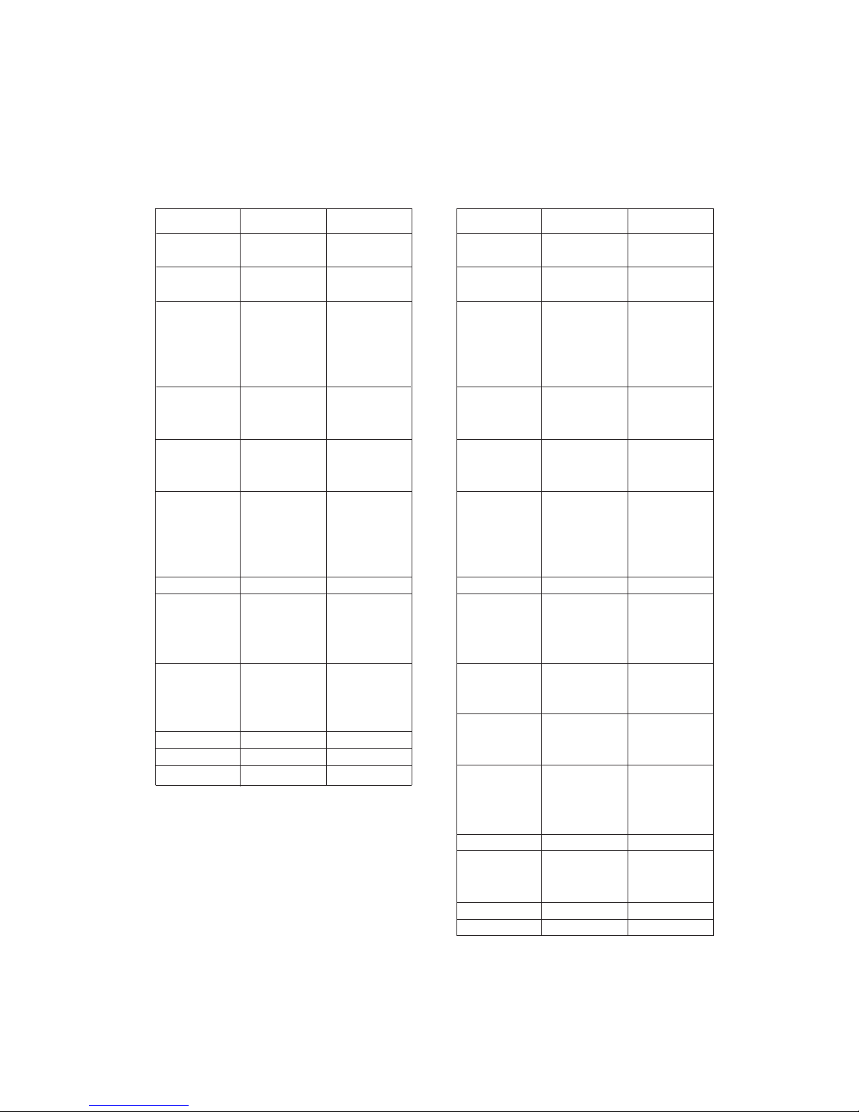
Displayable Monitor Specification
Displayable Monitor Specification
RGB / DVI mode
Resolution
640x350
720x400
640x480
848x480
800x600
Horizontal
Frequency(KHz)
Vertical
Frequency(Hz)
852x480
832x624
1024x768
1152x864
(RGB)
1152x870 (RGB)
1280x960 (RGB)
1280x1024 (RGB)
31.468
37.861
31.469
37.927
31.469
35.000
37.861
37.500
43.269
31.500
37.799
39.375
31.500
37.799
39.375
35.156
37.879
48.077
46.875
53.674
49.725
48.363
56.476
60.023
68.677
54.348
63.995
67.500
77.487
68.681
60.023
63.981
RGB / DVI mode
MT/MZ-42PM10/12X/20 series
MT/MZ-50PM10/20 series
Resolution
640x350
720x400
640x480
848x480
800x600
Horizontal
Frequency(KHz)
Vertical
Frequency(Hz)
852x480
832x624
1024x768
1360x768
1366x768
1152x864
1152x870
1280x960
1280x768
70.09
85.08
70.08
85.03
59.94
66.66
72.80
75.00
85.00
60.00
70.00
75.00
60.00
70.00
75.00
56.25 (RGB)
60.31
72.18
75.00
85.06
74.55
60.00
70.06
75.02
85.00
60.00
75.02
85.00
60.00
75.02
85.00
60.05
70.01
75.00
85.00
75.06
60.00
75.00
85.00
60.02
60.02
31.468
37.861
31.469
37.927
31.469
35.000
37.861
37.500
43.269
31.500
37.799
39.375
31.500
37.799
39.375
35.156
37.879
48.077
46.875
53.674
49.725
48.363
56.476
60.023
68.677
47.700
59.625
68.500
47.700
59.625
69.500
54.348
63.995
67.500
77.487
68.681
47.693
60.091
68.504
60.023
63.981
- 9 -
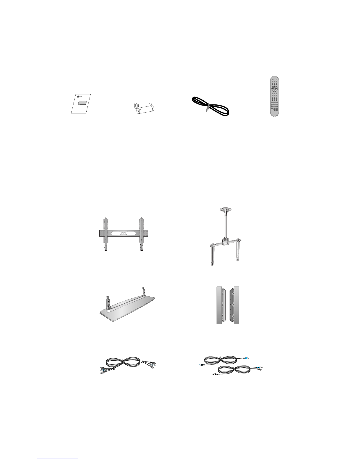
AS mark
LG TV
OwnerÕs Manual
1.5V
1.5V
Alkaline batteries
Power Cord
POWERMUTE
PIP INPUT
MULTIMEDIA
EXIT ARC
MENU
VOL
OK
1 2 3
4 5 6
7
PSM
SSM
8 9
0
VOL
SPLIT ZOOM
PIP/DW
SLEEP
SCAN-
SKIP-
WIN. SIZE
SCAN+
PLAY
POSITION
SKIP+
STOP
SWAP
POWER
PAUSE
INPUT SELECT
Remote Control handset
- Optional extras can be changed or modified for quality improvement without any notification new optional extras can be
added.
- Contract your dealer for buying these items.
Optional Extras
Accessories
Accessories
Tilt wall mounting bracket
404250 40 42 50
Video cables Audio cables
Ceiling mounting bracket
40
42
50
42
40
Desktop stand
Speakers
- 10 -
SPECIFICATIONS
NOTE : Specifications and others are subject to change without notice for improvement
.
V Application Range
This spec is sheet is applide to the 42Ó,50Ó PDP TV used RF-04GA chassis.
V Specification
Each part is tested as below without special appointment.
1) Temperature : 25
¡ 5¡C (77¡ 9¡F)
2) Relative Humidity: 65¡ 10%
3) Power Voltage: Standard Input voltage (100V -240V~, 50/60Hz)
* Standard Voltage of each product is marked by models.
4) Specification and performance of each parts are followed each drawing and specification by part number in
accordance with BOM.
5)
The receiver must be operated for about 20 minutes prior to the adjustment
.
V Test and Inspection Method
1) Performance : LGE TV test method followed.
2) Demanded other specification
Safety: CE, IEC specification
EMC : CE, IEC
Remark
Safety : IEC60065
EMI : EN55022
EMS : EN55024
Safety : IEC60065,IE60950
EMI : EN55022
Model Name
MZ-42PM10
MZ-42PM12X
MZ-50PM10
MZ-50PM20
MT-42PM10
MT-42PM20
MT-42PM12X
MT-50PM10
MT-50PM20
Market
EU
Non-EU
Market Place
EU
Non-EU
Chassis
RF-04GA
Model Name
MZ-42PM10
MZ-42PM12X
MZ-50PM10
MZ-50PM20
MT-42PM10
MT-42PM20
MT-42PM12X
MT-50PM10
MT-50PM20
Brand
LG
LG
- 11 -
V General Specification
1. General Specification (42Ó VGA MODULE)
2. General Specification (42Ó XGA MODULE)
3. General Specification (50Ó XGA MODULE)
Remark
PDP
LGE
Maker : NBK / Mitsui / LG Chemical
LGE SPEC
Maker : SONY / Murata / Sanken
Specification
42 inch wide Color Display Module
16:9
PDP42V6000
45% Total light transmittance (E- Mesh)
1) Temp : 0~40 deg
2) Humidity : 0~85%
1) Temp : -20~60 deg
2) Humidity : 0~85%
100-240V~, 50/60Hz
No
1
2
3
4
5
6
7
Item
Display Screen Device
Aspect Ratio
PDP Module
Screen Filter
Operating Environment
Storage Environment
Input Voltage
Remark
PDP
Maker : NBK / Mitsui / LG Chemical
LGE SPEC
Maker : SONY / Sanken
Specification
42 inch wide Color Display Module
16:9
PDP42X1A###, RGB Closed Type
45% Total light transmittance (E- Mesh)
1) Temp : 0~40 deg
2) Humidity : 0~85%
1) Temp : -20~60 deg
2) Humidity : 0~85%
AC100 ~ 240V, 50/60Hz
No
8
9
10
11
12
13
14
Item
Display Screen Device
Aspect Ratio
PDP Module
Screen Filter
Operating Environment
Storage Environment
Input Voltage
Remark
PDP
LGE
Maker : NBK / Mitsui / LG Chemical
LGE SPEC
Maker : SONY / Sanken
Specification
50 inch wide Color Display Module
16:9
PDP50X2###, RGB Closed Type
45% Total light transmittance (E- Mesh)
1) Temp : 0~40 deg
2) Humidity : 0~85%
1) Temp : -20~60 deg
2) Humidity : 0~85%
100-240V~, 50/60Hz
No
15
16
17
18
19
20
21
Item
Display Screen Device
Aspect Ratio
PDP Module
Screen Filter
Operating Environment
Storage Environment
Input Voltage
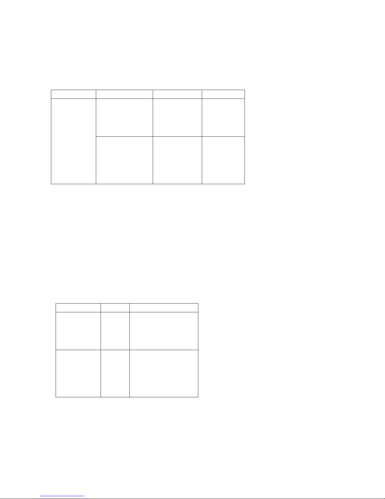
V Model Specification
1. MZ-42PM10 / 42PM12X / 50PM10 / 50PM20
2. MT-42PM10 / 42PM20 / 42PM12X / 50PM10 / 50PM20
- 12 -
Remark
4 System : PAL, B/G/I/D/K, SECAM L/,
NTSC4.43, PAL60
4 System : PAL, B/G/I/D/K, SECAM L/,
NTSC4.43, PAL60
Up to UXGA@60Hz/480P
Up to UXGA@60Hz/480P
DVI-D
L/R Input
Specification
EU
PAL, SECAM
PAL, SECAM, NTSC
Y/ Cb/ Cr, Y/ Pb/ Pr
RGB-PC/DTV
RGB-PC/DTV
DVI-PC/DTV
PC Audio, Component,S-VHS, CVBS
Discrete IR
No
22
23
24
25
26
27
28
29
30
Item
Market
Scart Jack (2EA )
S-AV Input (1EA )
Component Input (1EA )
RGB Input (1EA )
RGB Outpu t (1EA )
DVI Input (1EA )
Audio Input (4EA )
Wired Control
Remark
4 System : PAL, B/G/I/D/K, SECAM L/,
NTSC4.43, PAL60
4 System : PAL, B/G/I/D/K, SECAM L/,
NTSC4.43, PAL60
Up to UXGA@60Hz/480P
Up to UXGA@60Hz/480P
DVI-D
L/R Input
Specification
Non-EU
PAL, SECAM, NTSC
PAL, SECAM, NTSC
Y/ Cb/ Cr, Y/ Pb/ Pr
RGB-PC/DTV
RGB-PC/DTV
DVI-PC/DTV
PC Audio, Component,S-VHS, CVBS
Discrete IR
No
31
32
33
34
35
36
37
38
39
Item
Market
Scart Jack (2EA )
S-AV Input (1EA )
Component Input (1EA )
RGB Input (1EA )
RGB Outpu t (1EA )
DVI Input (1EA )
Audio Input (4EA )
Wired Control
- 13 -
ADJUSTMENT INSTRUCTIONS
1. Application Object
This spec sjeet os applied all of the 42Ó, 50Ó, RF-04GA
chassis bymanufacturing LG TV Plant or sort plant.
2. Specification
(1) Because this is not a hot chassis, it is not necessary to
use an isolation transformer. However, the use of isolation
transformer will help protect test instrument.
(2) Adjustment must be done in the correct order.
(3) The adjustment must be performed in the circumstance of
25±5¡C of temperature and 65±10% of relative humidity if
there is no specific designation.
(4) The input voltage of the receiver must keep 100-220V~,
50/60Hz.
(5) The receiver must be operated for about 15 minutes prior
to the adjustment.
O After RGB Full white HEAT-RUN Mode, the receiver must
be operated prior to adjustment.
O Enter into HEAT-RUN MODE
1) Press the POWER ON KEY on R/C for adjustment.
2) OSD display and screen display 100% full WHITE
PATTERN.
[ Set is activated HEAT-RUN without signal generator in
this mode.
[ Single color pattern(RED/BLUE/GREEN) of HEAT-RUN
mode uses to check pannel.
Caution) If you turn on a still screen more than 20 minutes
(Especially digital pattern, cross hatch pattern), a after
image may be occur in the black level part of the
screen.
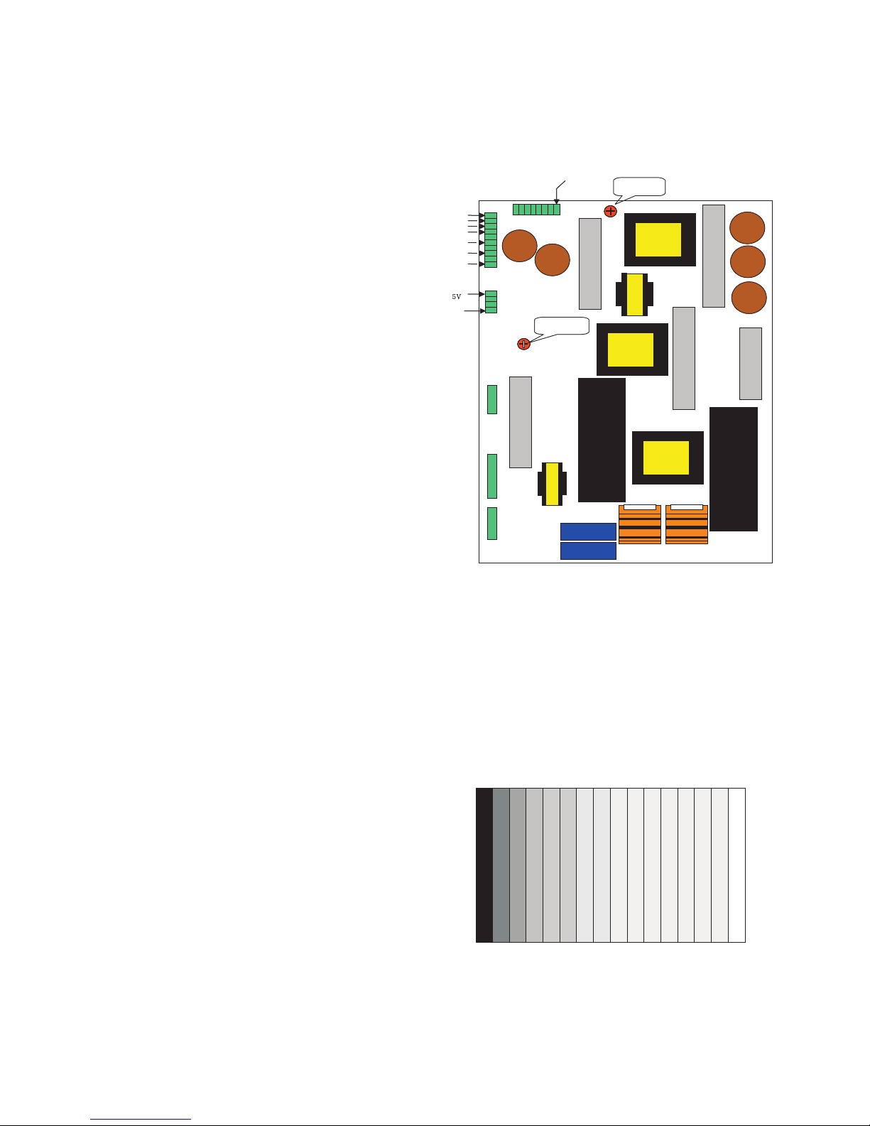
3. POWER PCB Assy Voltage
Adjustments
(Va, Vs Voltage Adjustments)
3-1. Test Equipment : D.M.M. 1EA
3-2. Connection Diagram for Measuring
Refer to [Fig 1]
3-3. Adjustment Method for
(1) Va Adjustment
1) After receiving 100% Full White Pattern, HEAT RUN.
2) Connect + terminal of D.M.M to Va pin of P805, connect
- terminal to GND pin of P805.
3) After turningVR351, voltage of D.M.M adjustment as
same as Va voltage which on lable of panel right/top
(Deviation; ±0.5V)
(2) Vs Adjustment
1) Connect + terminal of D.M.M to Vs pin of P805, connect
Ð terminal to GND pin of P805.
2) After turning RV551, voltage of D.M.M adjustment as
same as Va voltage which on label of panel right/top.
(Deviation; ±0.5V)
4. Auto RGB Color balance
4-1 Pattern Equipment :
PC Pattern Generator( 801F or VG828 )
(16Gray Scale Pattern output(RGB output Level: 0.7Vp-p))
4-2 Method of Auto RGB Color Balance
(1) Input RGB Source: 16Gray Scale Pattern output
(RGB output Level: 0.7Vp-p)
(2) Press ADJ KEY on R/C for adjustment.
(3) Press Vol. +KEY and Operate To Set.
(4) Auto-RGB OK means completed adjustment.
P805
P804
P806
P803
P802
P801
VR351
GND
GND
Va
Va
Vs
Vs
Vs
Vs ADJ
VR551
VR5
Vs ADJ
[Fig. 1] Connection Diagram of Power Adjustment for Measuring
[Fig. 2] Auto RGB Color Balance Test Pattern
 Loading...