

Page 1
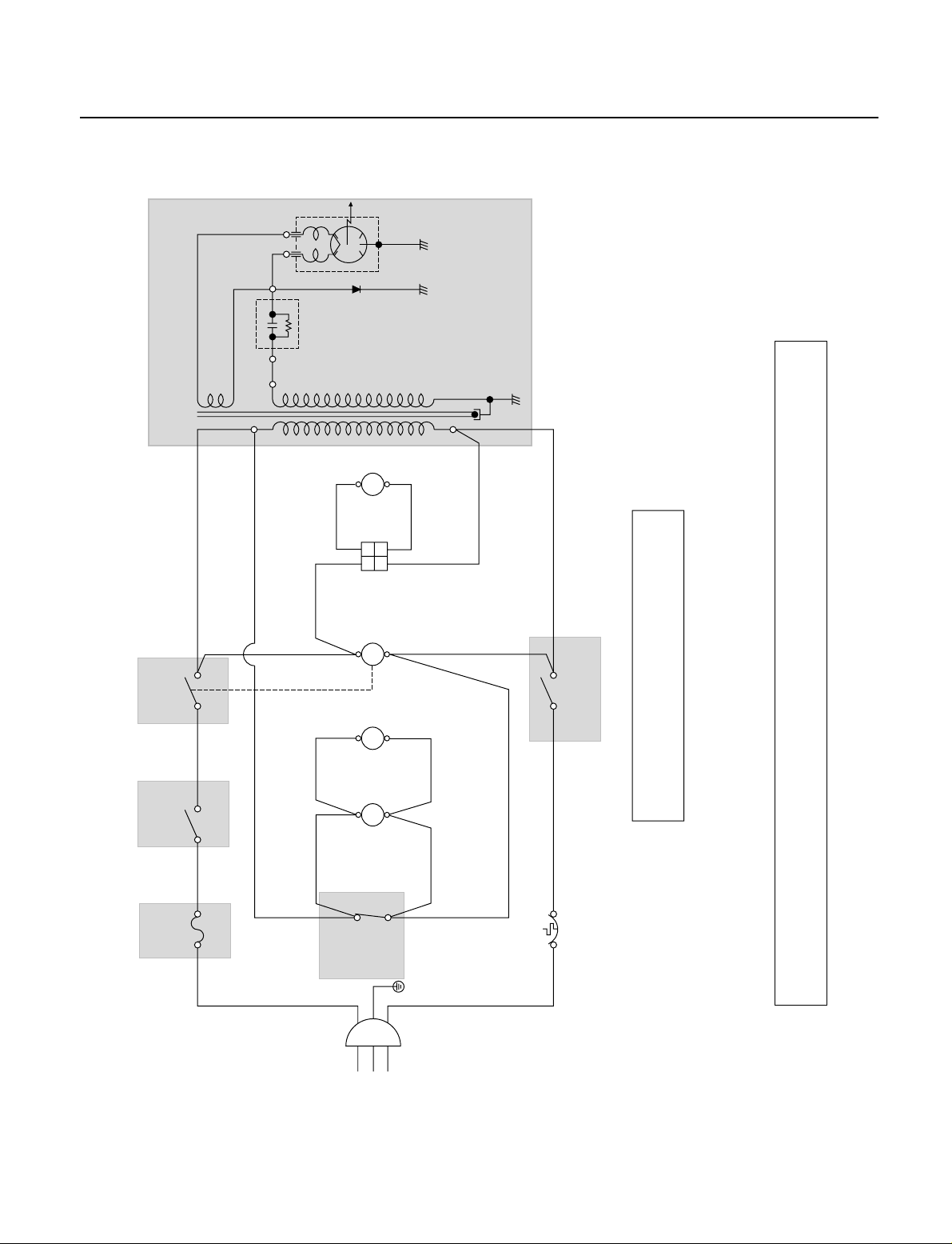
SCHEMATIC DIAGRAM
4-2
** NOTE : DOOR IS OPENED.
BK : BLACK BL : BLUE YL : YELLOW
RD : RED WH : WHITE PK: PINK
GN: GREEN
L
GN
YL
BL
WH WH
THERMOSTAT SECONDARY
SWITCH
BL
WH BL
YL
MONITOR
SWITCH
OVEN
LAMP
FAN
MOTOR
BK BK
BK
4
3
BK
RD
BK
WH
WH
T.T.M
T.M
22"1"1
F.MO.L
RD
TURN
TABLE
MOTOR
H.V DIODE
MAGNETRON
12
FUSE
15A
PRIMARY
SWITCH
TIMER
SWITCH
H.V
TRANSFORMER
H.V
CAPACITOR
N
AC 120V
60Hz
IMPORTANT SAFETY NOTE: THE COMPONENTS IN SHADED AREAS ON THIS SCHEMATIC DIAGRAM INCORPORATE SPECIAL FEATURES
IMPORTANT FOR PROTECTION FROM MICROWAVE RADIATION, FIRE, ELECTRICAL SHOCK, AND OTHER
HAZARDS. WHEN SERVICING IT IS ESSENTIAL THAT ONLY MANUFACTURER'S SPECIFIED PARTS
BE USED FOR THE CRITICAL COMPONENTS IN THE SHADED AREAS OF THE SCHEMATIC DIAGRAM.
NOTICE: SINCE THIS IS A BASIC SCHEMATIC DIAGRAM, THE VALUES OF COMPONENTS AND
SOME PARTIAL CONNECTIONS ARE SUBJECT TO CHANGE FOR IMPROVEMENT.
Page 2
CIRCUIT DESCRIPTION
GENERAL DETAILS
• When the door is closed, the primary switch is ON, the
secondary switch is ON, and the monitor switch opens
(contact COM and NO).
• The latches are secured by the latch board, the oven
light turns on while the oven is operation.
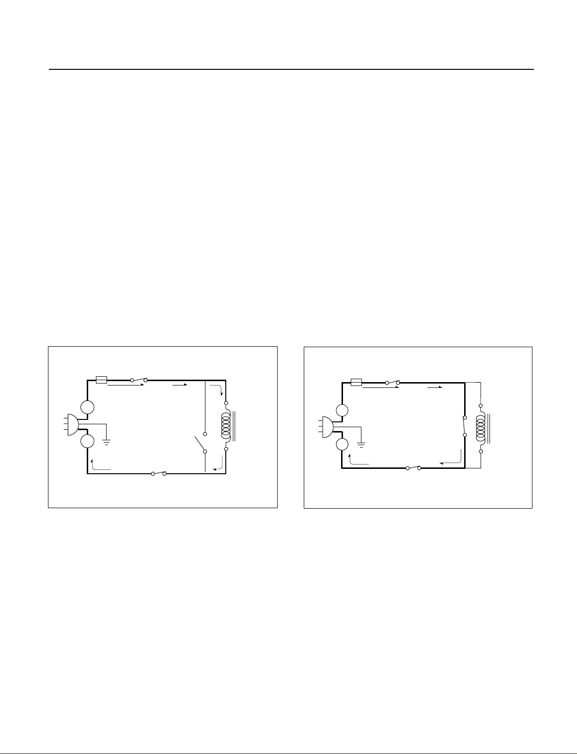
WHEN THE TIMER KNOB IS ROTATED
• When the timer knob is rotated, The contacts of timer
switch close.
• The contact of the secondary switch close the circuit.
• Power input is supplied to the high voltage transformer
through the fuse to the primary, timer and secondary
switches.
• Turntable rotates.
• The fan motor rotates and cools the magnetron by
blowing the air (coming from the intake on the
baseplate).
• The air is also directed into the oven to exhaust the
vapor in the oven through the upper plate.
• The timer starts rotating.
• 3.2 volts AC is generated from the filament winding of
the high voltage transformer. This 3.2 volts is applied to
the magnetron to heat the magnetron filament through
two noise-preventing choke coils.
• A high voltage of approximately 2100 volts AC is
generated in the secondary of the high voltage
transformer which is increased by the action of the high
voltage diode and charging of the high voltage
capacitor.
• The negative 4,000 Volts DC is applied to the filament
of the magnetron.
WHEN THE DOOR IS OPENED DURING
COOKING
• Both the primary switch and timer switches are cut off
primary winding voltage of the high voltage
transformer.
• When the door is opened, the secondary switch is
opened and when the door is closed, the secondary
switch is closed.
• The timer, turntable and fan motor stop.
• As the door is opened, if the contact of primary switch
fails to open, the fuse opens due to the large current
surge caused by the monitor switch activation, which in
turn stops magnetron oscillation.
4-3
L
FUSE
H.V.
TRANS-
FORMER
SECONDARY
SWITCH
PRIMARY
SWITCH
MONITOR
SWITCH
N
PRIMARY
FUSE
SWITCH
L
MONITOR
SWITCH
N
SECONDARY
SWITCH
H.V.
TRANS-
FORMER
 Loading...