

Page 1

www.lg.com
Please read this installation manual completely before installing the product.
Installation work must be performed in accordance with the national wiring
standards by authorized personnel only.
Please retain this installation manual for future reference after reading it
thoroughly.
WALL MOUNTED
Original instruction
[Representative] LG Electronics Inc. EU Representative : LG Electronics European Shared
Service Center B.V. Krijgsman 1, 1186 DM Amstelveen, The Netherlands
[Manufacturer] LG Electronics Inc. Changwon 2nd factory 84, Wanam-ro, Seongsan-gu,
Changwon-si, Gyeongsangnam-do, KOREA
For more information, Refer to the CD or LG Web site (www.lg.com).
INSTALLATION MANUAL
AIR
CONDITIONER
P/NO : MFL67855408
ENGLISH ITALIANO
ESPAÑOL
FRANÇAIS DEUTSCH
ΕΛΛΗΝΙΚΆ
ČEŠTINA
NEDERLANDS
POLSKI
LIMBA ROMÂNĂ
Page 2

2 Air Conditioner
Room Air Conditioner Installation Manual
CONTENTS
Safety Precautions............................3
Introduction........................................7
Symbols used in this manual ..........7
Installation ..........................................8
Installation Parts ..............................8
Installation Tools ..............................8
Installation Map................................9
Select the best Location .................9
Fixing Installation Plate..................10
Drill a Hole in the Wall ...................10
Flaring Work...................................11
Installation of Indoor Unit...............12
Connecting the Cables..................16
Checking the Drainage..................17
Test Running..................................18
o Some pieces of type "A" screws
o Connecting cable
o Installation guide map
o Pipes: Gas side
Liquid side
o Insulation materials
o Additional drain pipe
(Outer diameter...............15.5mm)
o Some pieces of type "B" screws
o Some pieces of type "C" screws
o Level gauge
o Screw driver
o Electric drill
o Hole core drill(ø70mm)
o Horizontal meter
o Flaring tool set
o Specified torque wrenches
1.8kg.m, 4.2kg.m, 5.5kg.m,
6.6kg.m
(different depending on model No.)
o Spanner ........................Half union
o A glass of water
o Hexagonal wrench(4mm)
o Gas-leak detector
o Vacuum pump
o Gauge manifold
o Owner's manual
o Thermometer
o Remote controller holder
Installation
Requirements
Required Parts Required Tools
Page 3

Installation Manual 3
Safety Precautions
To prevent the injury of the user or other people and property damage, the following instructions
must be followed.
n Be sure to read before installing the air conditioner.
n Be sure to observe the cautions specified here as they include important items related to safety.
n Incorrect operation due to ignoring instruction will cause harm or damage. The seriousness is
classified by the following indications.
n The meanings of the symbols used in this manual are as shown below.
This symbol indicates the possibility of death or serious injury.
This symbol indicates the possibility of injury or damage to properties only.
Be sure not to do.
Be sure to follow the instruction.
Safety Precautions
ENGLISH
n Installation
Always perform
grounding.
• Otherwise, it may cause
electrical shock.
Don’t use a power cord,
a plug or a loose socket which is damaged.
• Otherwise, it may cause
a fire or electrical shock.
For installation of the
product, always contact the service center
or a professional installation agency.
• Otherwise, it may cause
a fire, electrical shock,
explosion or injury.
Securely attach the
electrical cover to
indoor and pipe cover
to outdoor unit.
• If the electrical part cover
to indoor unit and pipe
cover to outdoor unit are
not attached securely, it
could result in a fire or
electric shock due to
dust, water, etc.
Always install an air
leakage breaker and a
dedicated switching
board.
• No installation may
cause a fire and electrical shock.
Do not keep or use
flammable gases or
combustibles near the
air conditioner.
• Otherwise, it may cause
a fire or the failure of
product.
Page 4

Safety Precautions
4 Air Conditioner
Do not share the outlet
with other appliances.
• It will cause an electric
shock or a fire due to
heat generation.
Do not use the damaged power cord.
• Otherwise, it may cause
a fire or electrical shock.
Do not modify or
extend the power cord
randomly.
• Otherwise, it may cause
a fire or electrical shock.
Take care so that the
power cord may not be
pulled during operation.
• Otherwise, it may cause
a fire or electrical shock.
Unplug the unit if
strange sounds, smell,
or smoke comes from it.
• Otherwise, it may cause
electrical shock or a fire.
Keep the flames away.
• Otherwise, it may cause
a fire.
n Operation
Do not install the product at a place
that there is concern of falling down.
• Otherwise, it may result in personal
injury.
Use caution when unpacking and
installing.
• Sharp edges may cause injury.
Ensure that an installation frame of the outdoor unit is not damaged due to use for a
long time.
• It may cause injury or an
accident.
Do not disassemble or
repair the product randomly.
• It will cause a fire or
electrical shock.
There is a risk of fire
and explosion.
•
Inert gas (nitrogen) should
be used when you check
plumbing leaks, cleaning
or repairs of pipes etc. If
you are using combustible
gases including oxygen,
product mayhave the risk
of fires and explosions.
Page 5

Safety Precautions
ENGLISH
Take the power plug
out if necessary, holding the head of the plug
and do not touch it with
wet hands.
• Otherwise, it may cause
a fire or electrical shock.
Do not use the power
cord near the heating
tools.
• Otherwise, it may cause
a fire and electrical
shock.
Do not open the inlet of
the indoor/outdoor unit
during operation.
• Otherwise, it may cause
electrical shock and failure.
Do not allow water to
run into electrical parts.
• Otherwise, it may cause
the failure of machine or
electrical shock.
Hold the plug by the
head when taking it
out.
• It may cause electric
shock and damage.
Never touch the metal
parts of the unit when
removing the filter.
• They are sharp and may
cause injury.
Do not step on the
indoor/outdoor unit and
do not put anything on
it.
• It may cause an injury
through dropping of the
unit or falling down.
Do not place a heavy
object on the power
cord.
• Otherwise, it may cause
a fire or electrical shock.
When the product is
submerged into water,
always contact the service center.
• Otherwise, it may cause
a fire or electrical shock.
Take care so that children may not step on the outdoor unit.
• Otherwise, children may be seriously injured due to falling down.
Installation Manual 5
Page 6

6 Air Conditioner
Safety Precautions
n Operation
Avoid excessive cooling and perform ventilation sometimes.
• Otherwise, it may do
harm to your health.
Use a soft cloth to
clean. Do not use wax,
thinner, or a strong
detergent.
• The appearance of the
air conditioner may deteriorate, change color, or
develop surface flaws.
Do not use an appliance for special purposes such as preserving animals vegetables,
precision machine, or
art articles.
• Otherwise, it may damage your properties.
Do not place obstacles around the flow inlet or outlet.
• Otherwise, it may cause the failure of appliance or an accident.
For R410A model, use piping, flare
nut and tools which is specified for
R410A refrigerant.
•
Using of (R22) piping, flare nut and tools
may cause abnormally high pressure in
the refrigerant cycle (piping), and possibly
result in explosion and injury.
It is desirable that the amount of
residual oil less than 40 mg/10m.
n Installation
Install the drain hose to
ensure that drain can
be securely done.
• Otherwise, it may cause
water leakage.
Install the product so that
the noise or hot wind
from the outdoor unit
may not cause any damage to the neighbors.
• Otherwise, it may cause
dispute with the neighbors.
Always inspect gas
leakage after the installation and repair of
product.
• Otherwise, it may cause
the failure of product.
Keep level parallel in
installing the product.
• Otherwise, it may cause
vibration or water leakage.
Thickness of copper
pipes used are as shown
“Flaring work” Table.
• Never use copper pipes
thinner than that in the
table even when it is
available on the market.
Do not use copper
pipes having a collapsed.
•
Otherwise, the expansion
valve or capillary tube may
become blocked with contaminants.
Page 7
Introduction
Installation Manual 7
ENGLISH
This symbol alerts you to the risk of electric shock.
This symbol alerts you to hazards that may cause harm to the
air conditioner.
This symbol indicates special notes.
NOTICE
Introduction
Symbols used in this Manual
Page 8
8 Air Conditioner
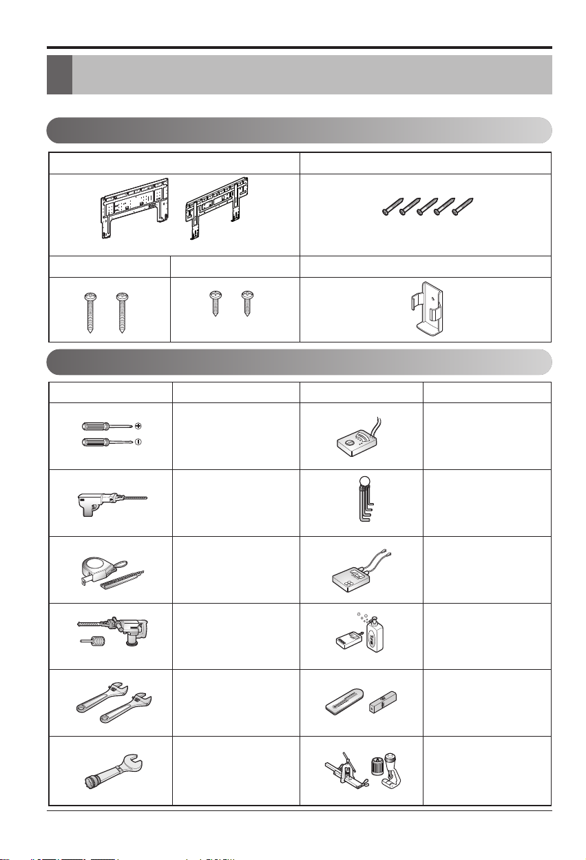
Installation Parts
Installation Tools
Installation
Read carefully, and then follow step by step.
Installation
Installation plate
The feature can be changed according a type of model.
Type "C" screwType "B" screw
Figure FigureName
Screw driver
Electric drill
Type "A" screw
Remote control holder
Name
Multi-meter
Hexagonal wrench
Measuring tape, Knife
Hole core drill
Spanner
Torque wrench
Ammeter
Gas-leak detector
Thermometer,
Level
Flaring tool set
Page 9
Installation Manual 9
ENGLISH
Installation
Indoor unit
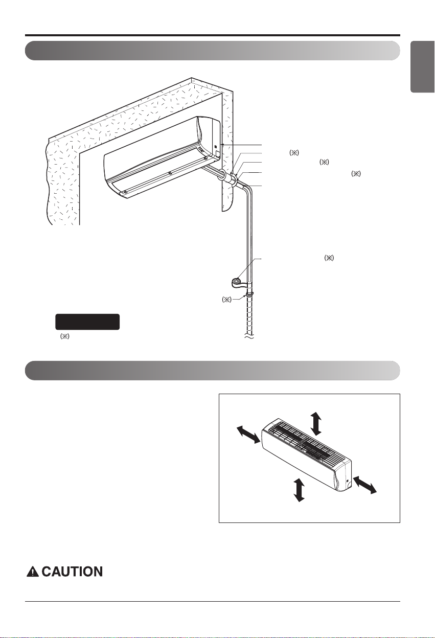
1. There should not be any heat or steam near
the unit.
2. Select a place where there are no obstacles
around of the unit.
3. Make sure that condensation drainage can be
conveniently routed away.
4. Do not install near a doorway.
5. Ensure that the interval between a wall and
the left (or right) of the unit is more than
100mm. The unit should be installed as high
as possible on the wall, allowing a minimum
of 200mm from ceiling.
6. Use a metal detector to locate studs to prevent unnecessary damage to the wall.
Select the best Location
Install the indoor unit on the wall where the height from the floor is more than 2300mm.
Installation Map
Vinyl tape (Wide)
• Apply after carrying out a
drainage test.
• To carry out the drainage
test, remove the air filters
and pour water into the heat
exchanger.
Saddle
Installation plate
Sleeve
Bushing-Sleeve
Putty(Gum Type Sealant)
Bend the pipe as closely
on the wall as possible,
but be careful that it
doesn't break.
You should purchase the installation parts.
NOTICE
- The feature can be changed according a
type of model.
More than
100
More than 2300
More than 200
More than
100
(Unit : mm)
Page 10
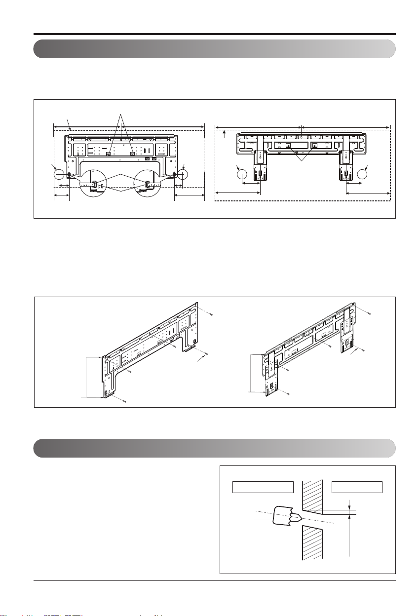
• Drill the piping hole with a ø65 hole core drill.
Drill the piping hole at either the right or the
left with the hole slightly slanted to the outdoor side.
Drill a Hole in the Wall
2. The wall you select should be strong and solid enough to prevent vibration.
• Mount the installation plate on the wall with type "A" screws. If mounting the unit on a concrete
wall, use anchor bolts.
• Mount the installation plate horizontally by aligning the centerline using Horizontal meter.
1. Measure the wall and mark the centerline. It is also important to use caution concerning the location of the installation plate. Routing of the wiring to power outlets is through the walls typically.
Drilling the hole through the wall for piping connections must be done safely.
Both Installation Plates can be used for this model.
Both Installation Plates can be used for this model.
Fixing Installation Plate
10 Air Conditioner
Installation
Place a level on raised tab
460 570
Installation Plate
Measuring Tape
Measuring
Tape Hanger
460 567
Unit
Outline
Ø65
Right
rear
56
piping
207
(Unit : mm) (Unit : mm)
Ø65
Left Rear
Piping
220
Place a level on raised tab
184
Installation plate
156
Ø65
Right Rear
Piping
307
Ø65
Left
rear
piping
Unit Outline
69
105
Installation Plate
Type "A" Screws
Chassis
Hook
Installation Plate
Type "A" Screws
Chassis
Hook
Indoor
WALL
Outdoor
5-7mm
(3/16in~5/16in)
Page 11
Indoor unit
Installation Manual 11
ENGLISH
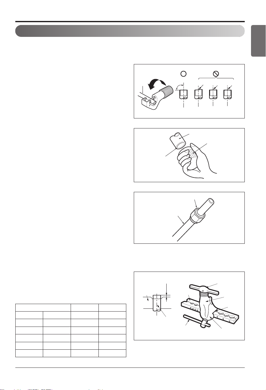
Flaring Work
Main cause for gas leakage is due to defect of flaring work. Carry out correct flaring work in the following procedure.
Cut the pipes and the cable.
1. Use the piping kit accessory or the pipes purchased locally.
2. Measure the distance between the indoor and
the outdoor unit.
3. Cut the pipes a little longer than measured distance.
4. Cut the cable 1.5m longer than the pipe length.
Burrs removal
1. Completely remove all burrs from the cut cross
section of pipe/tube.
2. While removing burrs put the end of the copper
tube/pipe in a downward direction while removing burrs location is also changed in order to
avoid dropping burrs into the tubing.
Putting nut on
• Remove flare nuts attached to indoor and out-
door unit, then put them on pipe/tube having
completed burr removal.
(not possible to put them on after finishing flare
work)
Flaring work
1. Firmly hold copper pipe in a bar with the dimension shown in below table table below.
2. Carry out flaring work with the flaring tool.
Outside diameter A Thickness
mm inch mm mm
Ø6.35 1/4" 1.1~1.3 0.7
Ø9.52 3/8" 1.5~1.7 0.8
Ø12.7 1/2" 1.6~1.8 0.8
Ø15.88 5/8" 1.6~1.8 1.0
Ø19.05 3/4" 1.9~2.1 1.0
Copper
pipe
Point down
Copper tube
Slanted Uneven Rough
90
Pipe
Flare nut
Reamer
Bar
"A"
Copper pipe
Clamp handle
Handle
Bar
Yoke
Cone
Red arrow mark
Page 12
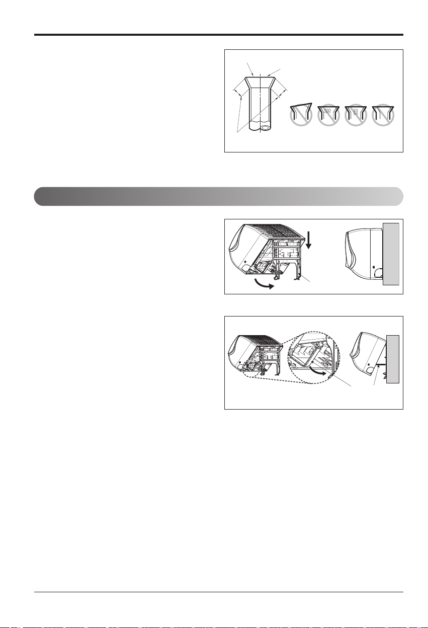
Check
1. Compare the flared work with the figure by.
2. If a flared section is defective, cut it off and do
flaring work again.
Installation of Indoor Unit
1. Hook the indoor unit onto the upper portion of
the installation plate.( engage the three hooks
at the top of the indoor unit with the upper edge
of the installation plate) Ensure that the hooks
are properly seated on the installation plate by
moving it left and right.
2. Unlock the tubing holder from the chassis and
mount between the chassis and installation
plate in order to separate the bottom side of the
indoor unit from the wall.
Installation
12 Air Conditioner
Smooth all round
Even length
all round
Inside is shiny without scratches
= Improper flaring =
Inclined
Surface
Cracked Uneven
damaged
Installation plate
thickness
Tubing Holder
Page 13
Installation
Installation Manual 13
ENGLISH
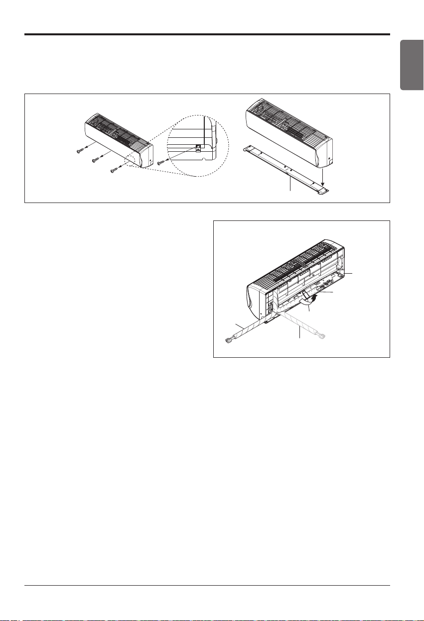
Connecting the Piping
1. Pull the screw cap at the bottom of the indoor unit.
2. Remove the chassis cover from the unit by loosing 3 screws
(Be careful not to scratch Horizontal Vane Main!)
3. Pull back the tubing holder.
4. Remove pipe port cover and position the tubing.
Right
Indoor unit back side view
Chassis Cover
Pipe Port
Left
Tubing holder
Backwards
Page 14
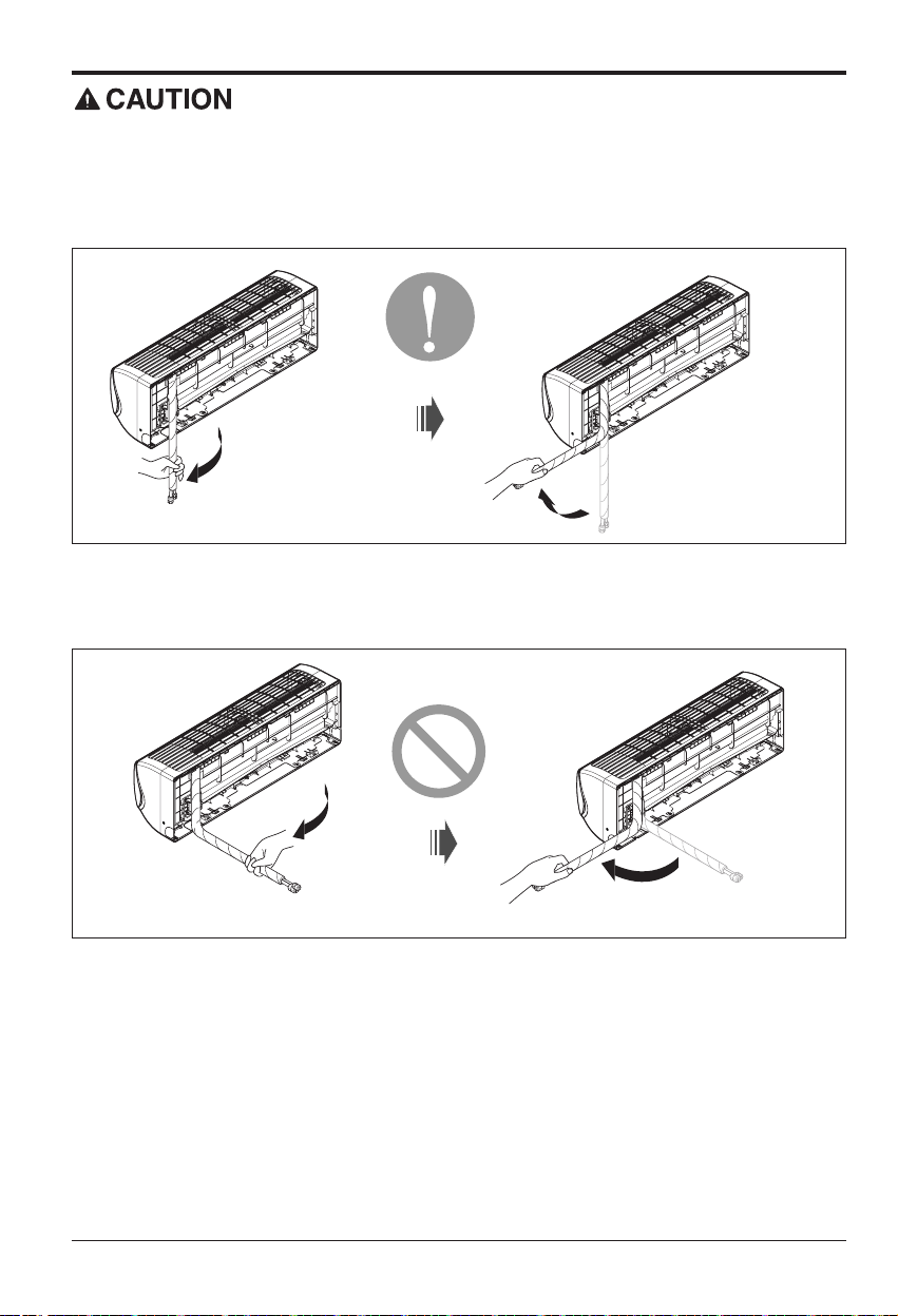
Installation Information. For right piping. Follow the instruction below.
Good case
• Press on the tubing cover and unfold the tubing to downward slowly. And then bend to the left side
slowly.
Bad case
• Following bending case from right to left directly may cause damage to the tubing.
Installation
14 Air Conditioner
Page 15
Installation
Installation Manual 15
ENGLISH
If the drain hose is routed inside the room insulate the hose with an insulation material* so that
dripping from sweating (condensation) will not damage furniture or floors.
* Foamed polyethylene or equivalent is recommended.
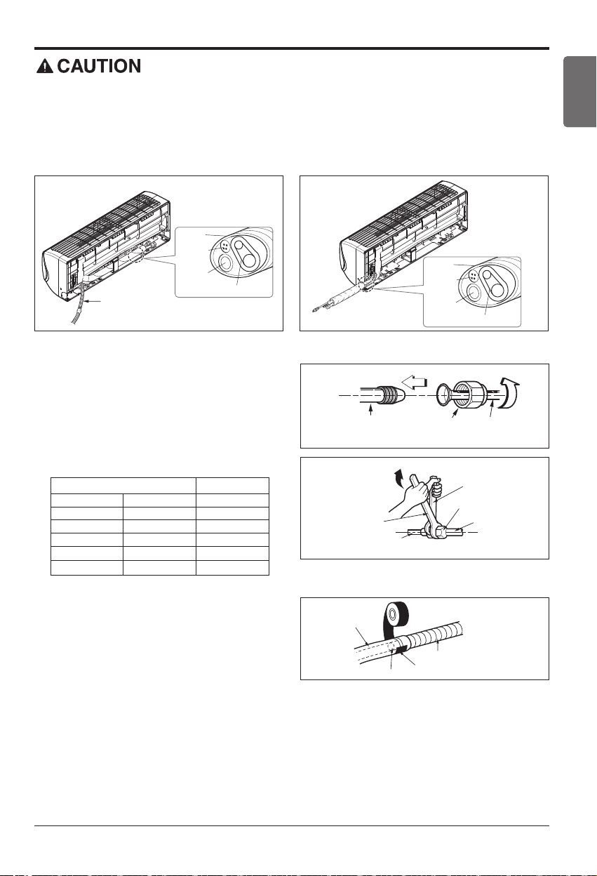
Connecting the installation pipe and
drain hose to the indoor unit.
1. Align the center of the pipes and sufficiently
tighten the flare nut by hand.
2. Tighten the flare nut with a wrench.
3. When needed to extend the drain hose of
indoor unit, assembly the drain pipe as shown
on the drawing.
mm inch kgf.m
Ø6.35 1/4 1.8~2.5
Ø9.52 3/8 3.4~4.2
Ø12.7 1/2 5.5~6.5
Ø15.88 5/8 6.3~8.2
Ø19.05 3/4 9.9~12.1
Outside diameter Torque
<Left side piping> <Right side piping>
Tape
Connecting
cable
Drain hose
Connecting pipe
Drain hose
Tape
Connecting
cable
Drain hose
Connecting pipe
Indoor unit tubing Flare nut Pipes
Torque wrench
Indoor unit tubing
Drain pipe
Adhesive
Open-end wrench (fixed)
Flare nut
Connection pipe
Indoor unit drain hose
Vinyl tape(narrow)
Page 16
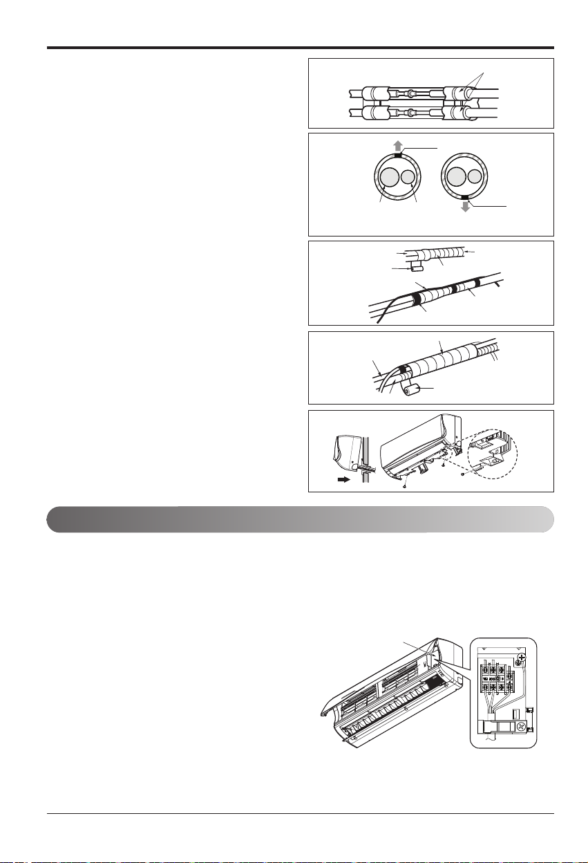
Wrap the insulation material around the connecting portion.
1. Overlap the connection pipe insulation material and the indoor unit pipe insulation material.
Bind them together with vinyl tape so that
there may be no gap.
2. Set the tubing cutting line upward.
Wrap the area which accommodates the rear
piping housing section with vinyl tape.
3. Bundle the piping and drain hose together by
wrapping them with vinyl tape sufficient
enough to cover where they fit into the rear
piping housing section.
Finishing the indoor unit installation
1.
Mount the tubing holder in the original positon.
2. Ensure that the hooks are properly seated on
the installation plate by moving it left and
right.
3. Press the lower left and right sides of the unit
against the installation plate until the hooks
engage into their slots (clicking sound).
4. Finish the assembly by screwing the unit to
the installation plate by using two pieces of
type "C" screws. And assemble a chassis
cover.
Vinyl tape(narrow)
Connection pipe
Connecting cable
Vinyl tape (wide)
Wrap with vinyl tape
Indoor unit pipe
Pipe
Gas Pipe
Liquid Pipe
Cutting Line
Cutting Line
Good Case Bad Case
* Tubing cutting line have to be upward.
Installation
16 Air Conditioner
Indoor unit
Connect the cable to the indoor unit by connecting the wires to the terminals on the control board
individually according to the outdoor unit connection. (Ensure that the color of the wires of the outdoor unit and the terminal No. are the same as those of the indoor unit.)
Connecting the Cables
1. Insert the connecting cable through the bottom side of indoor
unit and connect the cable (You can see detail contents
in 'Connecting the cables' section)
2. Secure the cable onto the control board with
the cable retainer.
3. Tape the tubing pipe, drain hose and the connection cable. Be sure that the drain hose is located at
the lowest side of the bundle.
Locating at the upper side can cause overflow
from the drain pan through the inside of the unit.
h Field wiring shall be done such that the currentcarrying conductors become taut before the earth-
ing conductor if the cord slips out of the cord anchorage.
Control Cover
Pipe
Drain hose
Insulation material
Wrap with vinyl tape
Vinyl tape(wide)
Type 'C' screw
Page 17
Installation
Installation Manual 17
ENGLISH
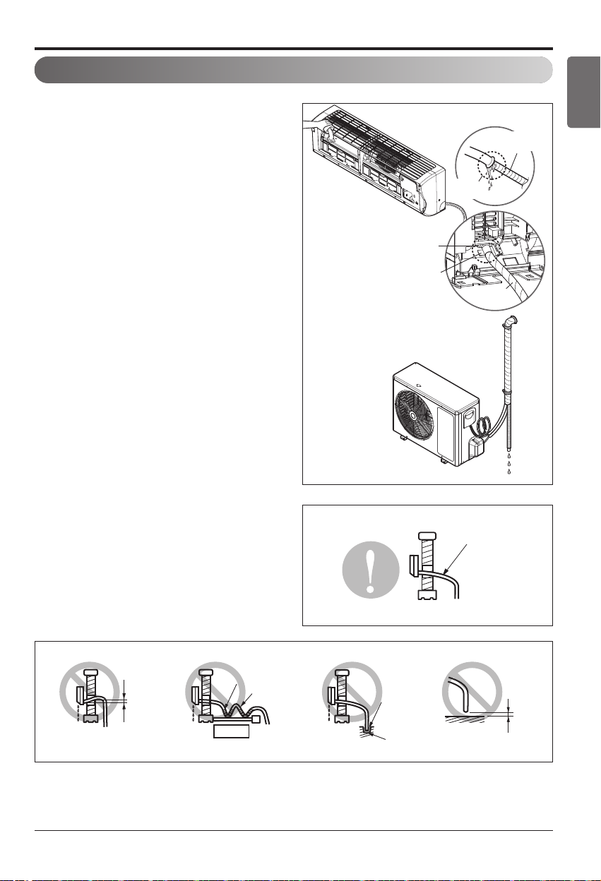
Checking the Drainage
To check the drainage.
1. Pour a glass of water on the evaporator.
2. Ensure the water flows through the drain hose
of the indoor unit without any leakage and
goes out the drain exit.
Drain piping
1. The drain hose should point downward for
easy drain flow.
2. Do not make drain piping like the following.
Drain Pan
Drain
Hose
Leakage
Checking
Connecting area
drain hose
Leakage
checking
Downward slope
Do not raise
Accumulated
drain water
Tip of drain hose
dipped in water
Air
Waving
Water
leakage
Water
leakage
Ditch
Less than
50mm gap
Water
leakage
Page 18

1. Check that all tubing and wiring are properly connected.
2. Check that the gas and liquid side service valves are fully open.
Installation of filter
1. Pull out the 3M Filter from the separately packed plastic bag.
2. Insert the 3M Filter into the left or right case.
3. Detach two nitto tapes from the plasma filter.
Prepare remote controller
1. Remove the battery cover by pulling it according to the arrow direction.
2. Insert new batteries making sure that the (+)
and (–) of battery are installed correctly.
3. Reattach the cover by pushing it back into
position.
• Use 2 AAA(1.5volt) batteries. Do not use
rechargeable batteries.
•
Remove the batteries from the remote controller
if the system is not used for a long time.
NOTICE
Test Running
Installation
18 Air Conditioner
3M Filter Plasma Filter
Page 19
 Loading...