

LG MPB3328CNE User Manual
RETAIN THESE INSTRUCTIONS
FOR FUTURE REFERENCE
OTL Report No. 116-F-36-5
HOMEOWNER'S CARE AND
OPERATION INSTRUCTIONS
B-VENT
MPB-33/35/40/45 SERIES
B-VENT GAS FIREPLACES
P/N 875,031M REV. A 02/2006
MODELS
WARNINGS
• Hot! Do not touch! The glass and
surfaces of this appliance will be hot
during operation and will retain heat
for a while after shutting off the appliance. Severe burns may result.
• Carefully supervise children in the
same room as appliance.
•
If small children are present in the home, it is
recommended that this appliance be fi tted with
a screen door or screen panel kit. See Page 17
for ordering information.
WARNING: IF THE INFORMATION IN THIS MANUAL
IS NOT FOLLOWED EXACTLY, A FIRE OR EXPLOSION MAY RESULT CAUSING PROPERTY DAMAGE,
PERSONAL INJURY OR LOSS OF LIFE.
FOR YOUR SAFETY: Do not store or use gasoline
or other fl ammables or liquids in the vicinity of
this or any other appliance.
FOR YOUR SAFETY: What to do if you smell
gas:
• DO NOT light any appliance.
• DO NOT touch any electrical switches.
• Do not use any phone in your building.
• Immediately call your gas supplier from a
neighbor’s phone. Follow your gas suppliers
instructions.
• If your gas supplier cannot be reached, call
the fi re department.
Installation and service must be performed by a
qualifi ed installer, service agency or gas supplier.
Millivolt Models
MPB3328CNM
MPB3328CPM
MPB3530CNM
A French manual is available upon request. Order P/N 875,031CF
Ce manuel d’installation est disponible en francais, simplement en
faire la demande. Numéro de la pièce 875,031CF.
MPB3530CPM
MPB4035CNM
MPB4540CNM
Electronic Models
MPB3328CNE
MPB3530CNE
MPB4035CNE
MPB4540CNE
AVERTISSEMENT: ASSUREZ-VOUS DE BIEN
SUIVRE LES INSTRUCTIONS DONNÉ DANS CETTE
NOTICE POUR RÉDUIRE AU MINIMUM LE RISQUE
D'INCENDIE OU POUR ÉVITER TOUT DOMMAGE
MATÉRIEL, TOUTE BLESSURE OU LA MORT.
POUR VOTRE SÉCURITÉ: Ne pas entreposer ni
utiliser d'essence ni d'autre vapeurs ou liquides
infl ammables dans le voisinage de cet appareil ou
de tout autre appareil.
POUR VOTRE SÉCURITÉ: Que faire si vous sentez
une odeur de gaz:
• Ne pas tenter d'allumer d'appareil.
• Ne touchez à aucun interrupteur. Ne pas vous
servir des téléphones se trouvant dans le batiment où vous vous trouvez.
• Evacuez la piéce, le bâtiment ou la zone.
• Appelez immédiatement votre fournisseur de
gaz depuis un voisin. Suivez les instructions du
fournisseur.
• Si vous ne pouvez rejoindre le fournisseur de
gaz, appelez le service dos incendies.
L'installation et service doit être exécuté par un
qualifi é installeur, agence de service ou le fournisseur de gaz.
CONGRATULATIONS!
In selecting this Lennox B-Vent Gas Appliance you have chosen the fi nest and most
dependable fi replace to be found anywhere. A beautiful, prestigious, alternative to a
wood burning fi replace. Welcome to a Family of tens of thousands of satisfi ed Lennox
Fireplace Owners.
Please read and carefully follow all of the instructions found in this manual. Please pay
special attention to the safety instructions provided in this manual. The Homeowner's
Care and Operation Instructions included here will assure that you have many years of
dependable and enjoyable service from your Lennox product.
TABLE OF CONTENTS
Introduction ......................................Page 2
General Information ..........................Page 2
Operation/Care of Your Appliance .....Page 3
Variable Flame Adjustment ................Page 4
Outside Combustion Air Control .......Page 5
Manual Limit Switch .........................Page 5
Maintenance Schedule ......................Page 6
Maintenance ......................................Page 7
Front Glass Enclosure Panel,
Removal and Installation ...............Page 7
Burner Adjustments ..........................Page 8
Millivolt Appliance Checkout .............Page 8
Electronic Appliance Checkout ..........Page 8
Logs, Rockwool, Vermiculite &
Volcanic Stone Placement .............Page 9
Wiring Diagrams ...............................Page 14
Warranty ...........................................Page 14
Replacement Parts ............................Page 14
Product Reference Information .........Page 14
Accessory Components ....................Page 15
Lighting Instructions – Millivolt ........Page 18
Lighting Instructions – Electronic .....Page 20
Troubleshooting Guide – Millivolt .....Page 22
Troubleshooting Guide – Electronic ..Page 22
Replacement Parts List .....................Page 24
INTRODUCTION
The millivolt appliances are designed to operate
on either natural or propane gas. A millivolt
gas control valve with piezo ignition system
provides safe, effi cient operation. External
electrical power is required to operate the
optional electrically powered components, if
installed. Electrical power must be wired during
appliance installation.
The electronic appliances are designed to
operate on either natural or propane gas. An
electronic intermittent pilot system provides
safe, effi cient operation. External electrical
power is required to operate these units.
These appliances comply with National Safety
Standards and are tested and listed by OMNITest Laboratories, Inc. (Report No. 116-F-__-__)
to ANSI Z21.50 (in Canada, CSA 2.22), and
CAN/CGA-2.17-M91 in both USA and Canada,
as vented gas fi replaces.
2
Installation must conform to local codes. In
the absence of local codes, installation must
comply with the current National Fuel Gas Code,
ANSI Z223.1 (NFPA 54). (In Canada, the current
CAN/CGA B149 installation code). Electrical
wiring must comply with local codes. In the
absence of local codes, installation must be in
accordance with the National Electrical Code,
NFPA 70 - (latest edition). (In Canada, the current
CSA C22.1 Canadian Electric Code).
DO NOT ATTEMPT TO ALTER OR MODIFY
THE CONSTRUCTION OF THE APPLIANCE OR
ITS COMPONENTS. ANY MODIFICATION OR
ALTERATION MAY VOID THE WARRANTY,
CERTIFICATION AND LISTINGS OF THIS UNIT.
WARNING
Improper installation, adjustment,
alteration, service or maintenance
can cause injury or property
damage. Refer to this manual. For
assistance or additional information
consult a qualifi ed installer, service
agency or the gas supplier.
GENERAL INFORMATION
Note: Installation and repair should be
performed by a qualifi ed service person. The
appliance should be inspected annually by a
qualifi ed professional service technician. More
frequent inspections and cleanings may be
required due to excessive lint from carpeting,
bedding material, etc. It is imperative that the
control compartment, burners and circulating air
passage ways of the appliance be kept clean.
S'assurer que le brùleur et le compartiment des
commandes sont propres. Voir les instructions
d'installation et d'utilisation qui accompagnent
l'appareil.
Provide adequate clearances around air openings and adequate accessibility clearance for
service and proper operation. Never obstruct
the front openings of the appliance.
Due to high temperatures the appliance should
be located out of traffi c and away from furniture
and draperies. Locate furniture and window
coverings accordingly.
NOTE: DIAGRAMS & ILLUSTRATIONS ARE NOT TO SCALE.
WARNING
These fi replaces are vented decorative gas appliances. Do not burn
wood or other material in these
appliances.
These appliances are designed to operate on
natural or propane gas only.
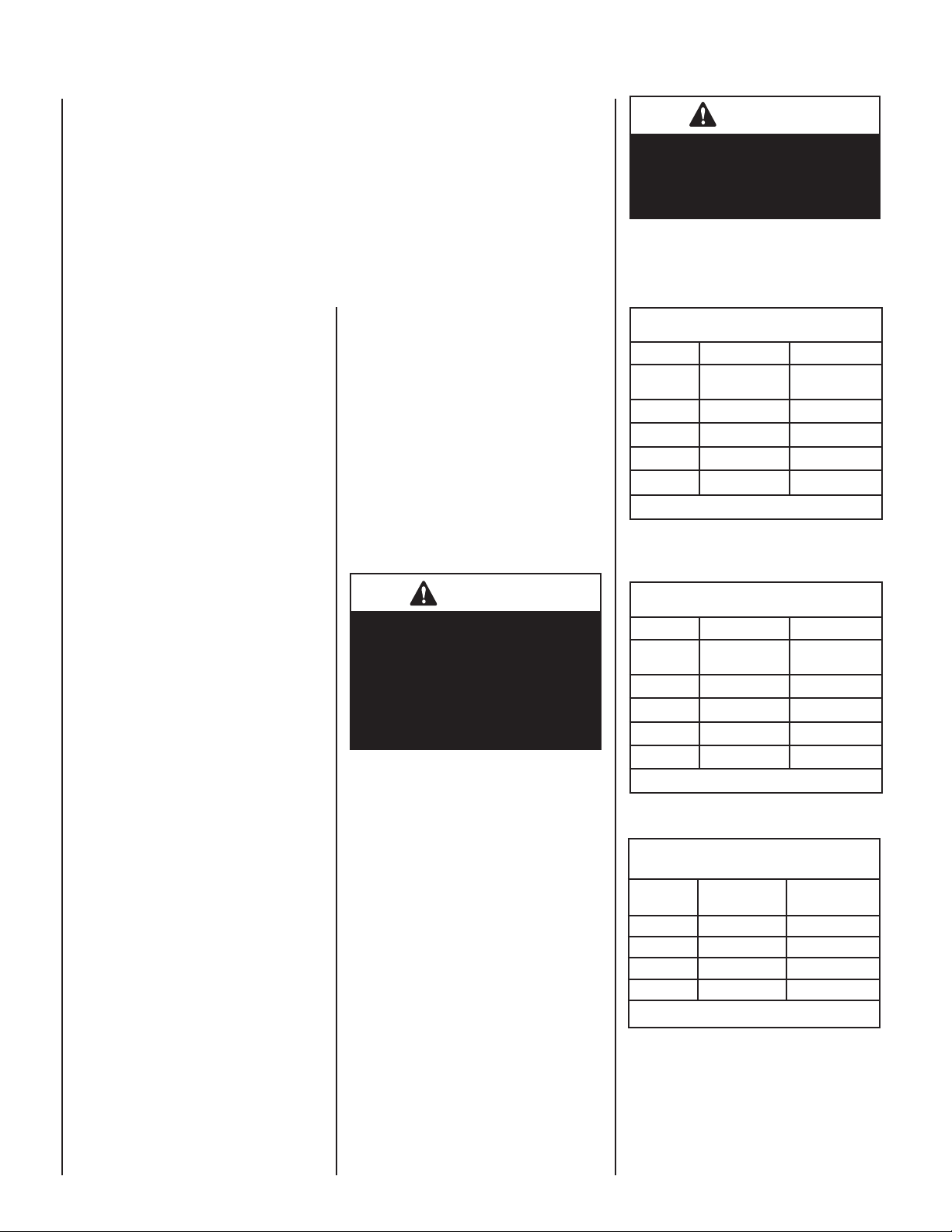
Input of millivolt models is variable. These rates
are shown in Table 1:
Millivolt Models with
Manually-Modulated Gas Valve
Natural Gas Propane Gas
Model Input Rate
MPB3328
MPB3530
MPB4035
MPB4540
Table 1
Electronic Models -
Electronic models have a fi xed rate gas valve.
Input of electronic models is shown in Table 2:
Model Input Rate
MPB3328
MPB3530
MPB4035
MPB4540
Table 2
Table 3 shows the units' orifi ce size for the
elevations indicated.
Elevation 0-4500 feet ( 0-1372 meters)
Models
MPB-3328 #47 (.0785") 1.2mm (.048")
MPB-3530 #44 (.086") #55 (.052")
MPB-4035 #37 (.104") 1/16"
MPB-4540 #36 (.1065") #52
Table 3
Maximum manifold pressure is 3.5 in. w.c. (0.87
kPa) for natural gas and 10 in. w.c. (2.49 kPa)
for LP/Propane gas.
Do not use these appliances if any part has been
under water. Immediately call a qualifi ed, professional service technician to inspect the appliance
and to replace any parts of the control system and
any gas control which have been under water.
(BTU/HR)
13,500 to 17,500 13,500 to 17,500
16,000 to 20,000 16,500 to 20,000
24,000 to 30,000 22,300 to 28,000
24,750 to 31,000 23,000 to 29,000
Electronic Models with
Fixed-Rate Gas Valve
Natural Gas Propane Gas
(BTU/HR)
17,500 17,500
20,000 20,000
30,000 28,000
31,000 29,000
Burner Orifi ce Sizes
NaturalGas
drill size (inches)
Input Rate
(BTU/HR)
Input Rate
(BTU/HR)
Propane Gas
drill size (inches)
(.0625")
(.0635")
Ne pas se servir de cet appareil s'il a été plongé
dans l'eau, complètement ou en partie. Appeler
un technicien qualifi é pour inspecter l'appareil et
remplacer toute partie du système de contrôle et
toute commande qui ont été plongés dans l'leau.
Test gauge connections are provided on the front
of the millivolt gas control valve (identifi ed OUT
for the manifold side and IN for inlet pressure. A
1/8" NPT test gauge connection is provided on the
electronic gas control valve adjacent to the outlet
to the main burner.
Minimum inlet gas pressure to these appliances is
5.0 inches water column (1.24 kPa) for natural gas
and 11 inches water column (2.74 kPa) for propane
for the purpose of input adjustment.
Maximum inlet gas supply pressure to these appliances is 10.5 inches water column (2.61 kPa) for
natural gas and 13.0 inches water column (3.23
kPa) for propane.
The appliance must be isolated from the gas supply
piping system (by closing its individual manual
shut-off valve) during any pressure testing of the
gas supply piping system at test pressures equal
to or less than 1/2 psig (3.5 kPa).
The appliance and its individual shut-off valve
must be disconnected from the gas supply piping
system during any pressure testing of that system
at pressures in excess of 1/2 psig (3.5 kPa).
These appliances must not be connected to a
chimney or fl ue serving a separate solid fuel
burning appliance.
Any safety guard or screen removed for servicing
the appliance must be replaced prior to operating
the appliance.
WARNING
B-Vent appliances are not designed
to operate in negatively pressured
environments (pressure within the
home is less than pressures outside).
Significant negatively pressured
environments caused by weather,
home design, or other devices may
impact the operation of these appliances. Negative pressures may result
in poor fl ame appearance, sooting,
damage to property and/or severe
personal injury. Do not operate these
appliances in negatively pressured
environments.
Carbon Monoxide Poisoning: Early signs of
carbon monoxide poisoning are similar to the fl u
with headaches, dizziness and/or nausea. If you
have these signs, obtain fresh air immediately.
Turn off the gas supply to the appliance and have
it serviced by a qualifi ed professional, as it may
not be operating correctly.
WARNING
Failure to comply with the installation and operating instructions provided in this document will result in
an improperly installed and operating appliance, voiding its warranty.
Any change to this appliance and/or
its operating controls is dangerous.
Improper installation or use of this
appliance can cause serious injury
or death form fi re, burns, explosion
or carbon monoxide poisoning.
WARNING
Children and adults should be
alerted to the hazards of high surface temperatures. Use caution
around the appliance to avoid burns
or clothing ignition. Young children
should be carefully supervised
when they are in the same room
as the appliance.
WARNING
Do not place clothing or other fl ammable materials on or near this
appliance.
AVERTISSEMENT
Surveiller les enfants. Garder les
vêtements, les meubles, l'essence
ou autres liquides à vapeur infl ammables lin de l'appareil.
OPERATION AND CARE OF YOUR
APPLIANCE
Appliance operation may be controlled through a
remotely located optional wall switch. Separate
switches may provide independent control for
the remote controlled fi replace operation (optional equipment).
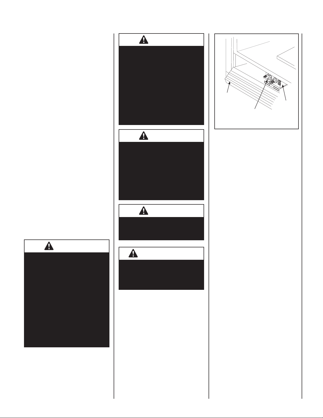
In lieu of remote or remote wall switch operation,
the appliance must be operated directly through
the controls located on the front of the valve
located within the control compartment which is
located behind the control compartment access
panel below the appliance front glass enclosure
panel. See Figure 1.
NOTE: DIAGRAMS & ILLUSTRATIONS ARE NOT TO SCALE.
Control
Compartment
Access Panel
Piezo Igniter
Figure 1
Millivolt
Gas Valve
Gas Controls/Control Compartment
Access
The gas controls can be found behind the control
compartment access panel. To open the control
compartment access panel, actuate the spring
loaded magnetic catches securing the panel.
First, gently depress the upper right top corner
of the panel until the magnet catch "pops" the
door free. Then, gently pulling the panel forward,
disengage the left magnet catch and allow the
panel to swing down to open.
Operation of millivolt and electronic gas control
systems are different. Before lighting and operating your appliance determine if you have a
millivolt or electronic appliance. See Figure 1
for access to the control compartment.
Millivolt appliances will be fi tted with the gas
control valve shown in Figure 3 on Page 4.
Appliances with electronic systems will be fi tted with the electronic valve shown in Figure
2 on Page 4.
Familiarize yourself with the gas control valve
that your appliance uses.
Millivolt Appliances -
To light millivolt appliances refer to the detailed
lighting instructions found on Page 18 (English)
and Page 19 (French). Millivolt appliance
lighting instructions may also be found on the
pull-out lighting instruction labels attached to
the gas control valve. Refer to Figure 3 on Page
4 for the location of the piezo Igniter.
Millivolt appliances may be fi tted with an optional
burner ON/OFF Rocker Switch. The optional ON/
OFF Rocker switch will be installed in the bracket
just beneath the gas control valve. Once the pilot
is lit, the ON/OFF rocker switch will control the
appliance ON/OFF operation. To operate: Toggle
the switch between its ON and OFF positions.
3
If your millivolt appliance is equipped with an
optional remote wall switch or remote control
kit and the pilot is lit, the appliance main burner
may be turned on and off with the wall switch
or remote control.
Electronic Appliances -
To light electronic appliances refer to the detailed
lighting instructions found in both English and
French on Pages 20 and 21 of these instructions respectively. Electronic appliance lighting
instructions may also be found on the pull out
lighting instruction labels attached to the gas
control valve. If your electronic appliance is
equipped with an optional remote wall switch
or remote control kit the appliance main burner
may be turned on and off with the wall switch
or remote control.
If your electronic appliance is not equipped
with a wall switch or remote control, the main
burner must be turned off and on with the gas
control switch. Toggle the switch from ON to
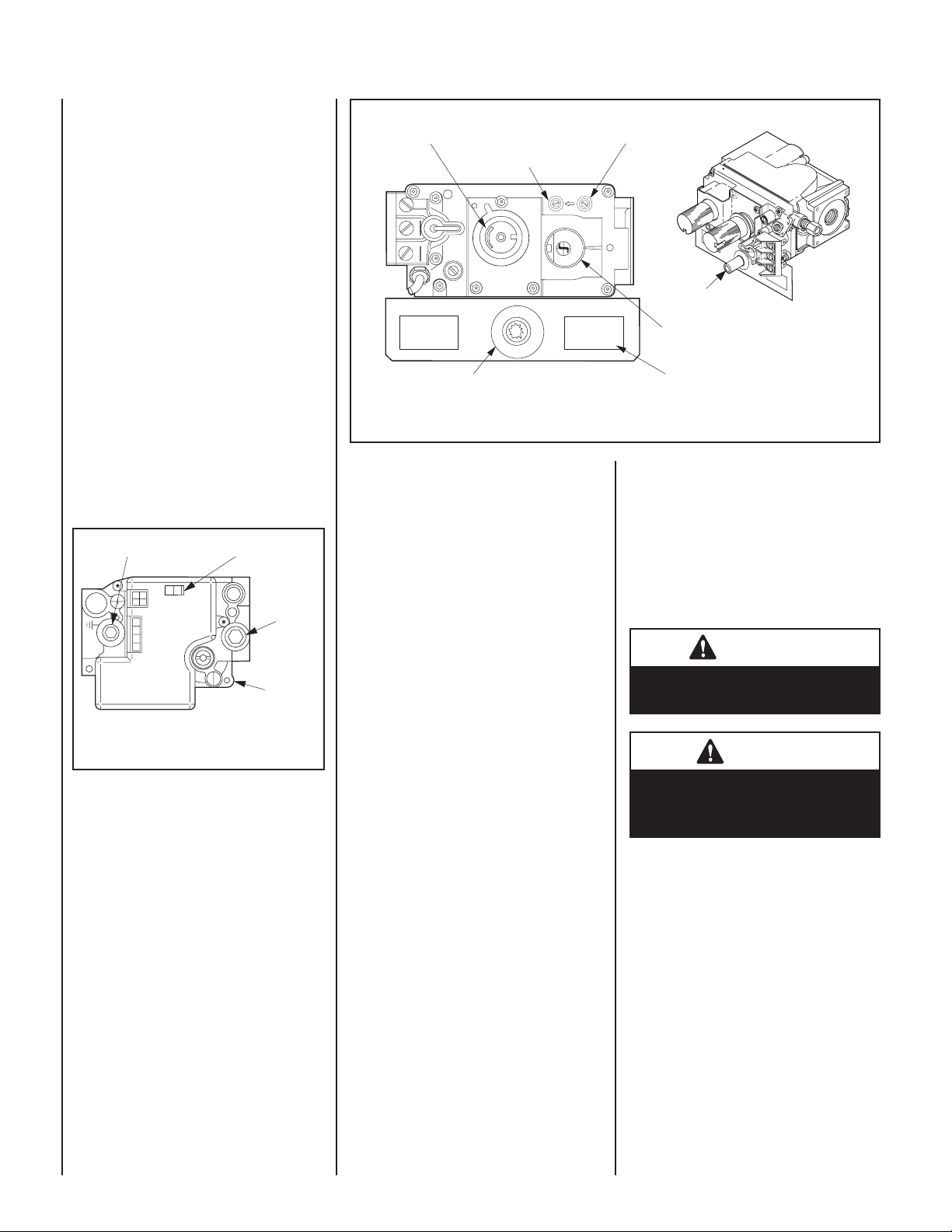
OFF to operate the main burner .
O
FO
N
F
ON/OFF Switch
NI
I
S
P
Inlet
Pressure
Port
Electronic
Gas Control
Valve
Manifold Pressure Port
C
O
TN
OR
L
GI
N
I
T
ER
Honeywell Electronic Gas Valve
Figure 2
Variable Flame Height Adjustment
Inlet Pressure Port
Manifold Pressure Port
IN
T
P
HT
HTPT
T
I
H
L
W
O
P
I
L
O
Piezo Igniter
OUT
F
F
O
P
I
L
i
O
t
T
O
N
Optional Burner ON/OFF Rocker Switch Location
Figure 3
3. Keep lower control compartment clean by
vacuuming or brushing at least twice a year.
More frequent cleaning may be required due to
excessive lint from carpeting, bedding materials,
etc. It is important that control compartments,
burners and circulating air passageways of the
appliance be kept clean.
4. Always turn off gas to the pilot (millivolt
appliances) before cleaning. Before re-lighting,
refer to the lighting instructions in this manual.
Instructions are also found on a pull-out panel
located on the fl oor of the appliance.
5. Always keep the appliance area clear and
free from combustible materials, gasoline and
other fl ammable liquids.
Piezo Igniter
Main Gas
Control Knob
(One of Two Places)
SIT Millivolt Gas Valve
6. Remember, Millivolt appliances have a
continuous burning pilot fl ame. Exercise caution when using products with combustible
vapors.
7. Clean the front glass enclosure only when
necessary. Wipe surface with clean, dampened,
soft cloth. Follow with dry, soft towel as desired.
Take care not to scratch the glass surface.
WARNING
Do not use abrasive cleaners. Never
clean the glass when it is hot.
CAUTION
Variable Flame Height Adjustment
( Millivolt Appliances only)
1. All Millivolt appliances are equipped with
a variable gas control valve. Flame height for
these models may be adjusted through a range
between fi xed low and high settings, alternately,
while the appliance is in operation. Adjust
the fl ame height as desired after lighting the
appliance by rotating the variable adjustment
control knob located on the front of the valve
(refer to Figure 3).
2. When lit for the fi rst time, this appliance will
emit a slight odor for an hour or two. This is due
to the “burn-in” of internal paints and lubricants
used in the manufacturing process.
4
Do not attempt to touch the front
enclosure glass with your hands
while the fi replace is in use.
NOTE: DIAGRAMS & ILLUSTRATIONS ARE NOT TO SCALE.
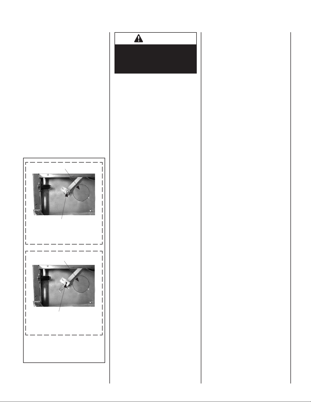
Outside Combustion Air Controls
Many appliances are equipped, when installed,
with an outside (make-up air) vent system that
is designed to provide the appliance with outside
make-up air for combustion when in operation.
The combustion air control lever for the outside
air system is standard on all appliances but
should not be operated if the complete system
is not installed. Refer to Figure 4. When the
complete outside air vent system is installed,
the installer will remove the securing screw from
the combustion air control lever located on the
left side of the fi replace bottom opening.
If the securing screw has not been removed
and you have reason to believe that you have
a complete outside air system, contact your
distributor to have your appliance inspected for
the presence of the complete system. DO NOT
assume that you have this system in place.
Outside Air Control Lever
Outside Air Control Lever
Securing Screw
Air Shutter in Closed Position
Outside Air Control Lever
Outside Air Control Lever
Securing Screw Removed
Air Shutter in Open Position
Combustion Air Control Lever
and Securing Screw Location
Figure 4
WARNING
Do not operate the shutoff lever
unless a complete outside combustion air system has been installed
with your appliance.
To open the outside air shutter, open the bottom
control access panel, reach into control compartment and pull the combustion air control
lever all the way out. The outside air shutter
should be fully open when the fi replace is in
use and completely closed when the fi replace
is not being used. Closing it when not in use
will prevent outside cold air from entering the
dwelling.
Step 13. Spillage Test and Safety Limit
Switch Operation
Spillage Test
After appliance installation, perform this spillage test to verify that proper venting conditions
exist:
1 - Place unit in its normally-operated condi-
tion, that is, with the glass enclosure panel
in place.
2 - Close all doors and windows in the room.
Turn on all exhaust fans in the house.
3 - Light the appliance.
4 - Wait 15 minutes.
5 - To check for venting action, start by holding
a smoke producing device within an inch
of one edge (side edge, not top or bottom
edge) of the glass enclosure panel. The
smoke should be drawn toward the edge
of the glass enclosure panel. Continue the
test by moving the smoke producing device
along the entire length of both side-edges
of the glass door.
6 - If the smoke is not drawn towards the
edges of the glass door turn off the
appliance and call a qualifi ed service
technican.
Manually-Reset Safety Limit Switch
This appliance is equipped with a manually-reset
blocked fl ue safety limit switch. Refer to Figure
5 on Page 7 for its location. If, during appliance
operation, the fl ame goes out (independently of
the burner on/off wall switch), it may be due to
the operation of this safety limit switch. First
allow the appliance to cool. Remove top louver
panel. Then reset the safety limit switch by
pushing the red reset button, located between
the wire terminals, on the back of the switch.
See Detail A of Figure 5 for location.
The appliance should then relight and remain
lit. Reinstall top louver panel. If the appliance
does not relight, turn off the appliance and call
for a qualifi ed service technician.
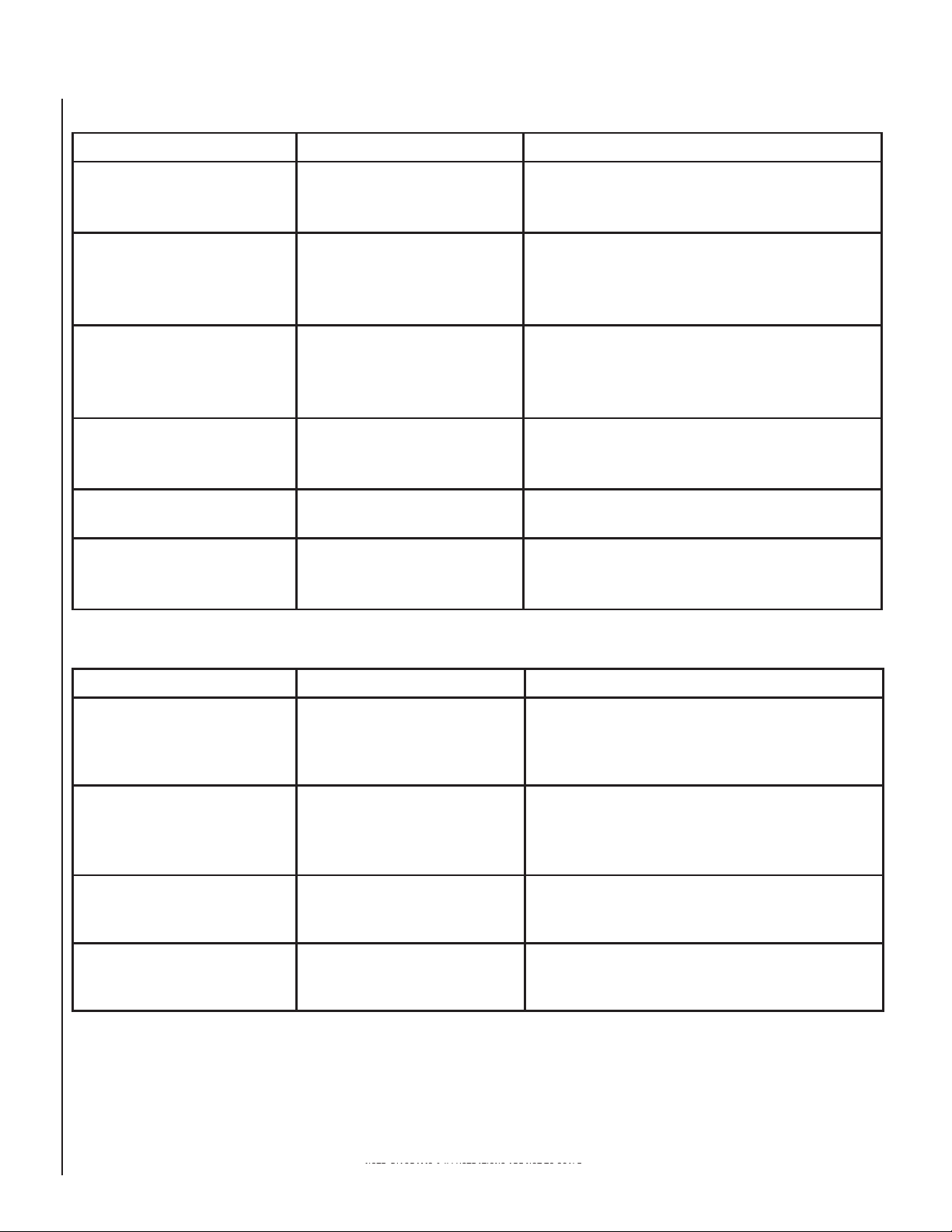
To replace the blocked fl ue safety limit
switch refer to Figure 5 on Page 7 (Details
B and C):
NOTE - This procedure should only be performed
by a qualifi ed service technician.
Important - Turn electrical power off before
beginning this procedure.
1 - Lower the bottom control compartment
access panel. Remove the glass enclosure
panel: open the latch (located in the center
of the unit front opening, under the fi rebox
fl oor) securing the glass enclosure panel.
Remove the panel by tilting it outward at
the bottom and lifting it up. Set the door
aside protecting it from inadvertent damage. See Figure 6 on Page 7.
2 - Remove the lintel securing screws (3) and
then remove the lintel. One of the lintel
cabinet top holes is shown in Figure 5
(Detail B).
3 - Remove the scoop securing screws (3)
and then remove the scoop. See Figure
5 (Detail B).
4 - Remove the safety switch bracket securing
screws (2), and pull the switch/bracket
assembly, with low voltage wires attached,
through the side panel slot into the fi rebox.
See Figure 5 (Detail C).
5 - Replace the switch.
6 - Reinstall the switch/bracket assembly.
7 - Reinstall the scoop and lintel.
8 - Reinstall the glass enclosure panel.
9 - Raise the bottom control compartment
access panel.
10 - The appliance should then relight and
remain lit. If this does not occur, check
unit for a blocked fl ue condition.
NOTE: DIAGRAMS & ILLUSTRATIONS ARE NOT TO SCALE.
5
MAINTENANCE SCHEDULE - Annually (Before the onset of the Burning Season)
MAINTENANCE TASK ACCOMPLISHING PERSON PROCEDURE
Inspecting/Cleaning Burner, Logs
and Controls
Check Flame Patterns and Flame
Height
Inspecting/Cleaning Pilot and Burner Qualifi ed Service Technician
Checking Vent System Qualifi ed Service Technician Inspect the vent system at the top and at the base (within the
Appliance Checkout Qualifi ed Service Technician Perform the appropriate appliance checkout procedure detailed
Replacing Rockwool Ember Materials Homeowner/Qualifi ed Service
Qualifi ed Service Technician Inspect valve and ensure it is properly operating. Check piping
for leaks. Vacuum the control compartment, fi replace logs and
burner area.
Qualifi ed Service Technician
Technician
Refer to Figure 10 (MPB-3328), Figure 11 (MPB-3530) or Figure
12 (MPB-4035 & MPB-4540) on Page 9 and verify the fl ame
pattern and height displayed by the appliance conforms to the
picture. Flames must not impinge on the logs.
Refer to Figures8 or 9 on Page 8. Remove any surface build-up
on pilot and burner assembly. Wipe the pilot nozzles, igniter/
fl ame rod and hood. Ensure the pilot fl ame engulfs the fl ame
sensor as shown.
fi rebox) for signs of blockage or obstruction. Look for any signs
of dislocation or deterioration of the vent components.
in this manual.
Remove old ember materials (rockwool) and vacuum the
ember placement area. Place new embers as described on
Pages 9-13.
MAINTENANCE SCHEDULE - Periodically (After the Burning Season)
MAINTENANCE TASK ACCOMPLISHING PERSON PROCEDURE
Cleaning Firebox Interior Homeowner Carefully remove logs, embers (rockwool), and volcanic stone.
Vacuum out interior of the fi rebox. Clean fi rebox walls. Replace
logs, embers (rockwool) and volcanic stone as detailed in this
manual (see Pages 9-13 ).
Check Flame Patterns and Flame
Height
Checking Vent System Homeowner Inspect the vent system at the top and at the base (within the
Cleaning Front Glass Enclosure Panel Homeowner Clean as necessary following the directions provided in this
Homeowner
Refer to Figure 10 (MPB-3328), Figure 11 (MPB-3530) or Figure
12 (MPB-4035 & MPB-4540) on Page 9 and verify the fl ame
pattern and height displayed by the appliance conforms to the
picture. Flames must not impinge on the logs.
fi rebox) for signs of blockage or obstruction. Look for any signs
of dislocation of the vent components.
manual. DO NOT TOUCH OR ATTEMPT TO CLEAN GLASS
WHILE HOT.
6
NOTE: DIAGRAMS & ILLUSTRATIONS ARE NOT TO SCALE.
Detail A
w
Fire Box Top
Detail B
Fire Box Top
Detail C
Wire
Termianls
Cabinet
Corner
Back Of
Limit
Switch
Door
Frame
Lintel Securing Screw
Hole in Cabinet Top
Scoop
Scoop Securing Screws
Lintel Securing-Scre
Hole in Cabinet Top
Limit/Bracket
Securing Screws
Limit
Refer to the maintenance schedule for maintenance tasks, procedures, periodicity and
by whom they should be performed. Always
verify proper operation of the appliance after
servicing.
IMPORTANT: TURN OFF GAS AND ANY
ELECTRICAL POWER BEFORE SERVICING
THE APPLIANCE.
Front Glass Enclosure Panel, Removal
and Installation.
WARNING
Never operate the appliance without the glass enclosure panel in
place and secure. Do not operate
appliance with the FRONT glass
panel cracked, broken or missing.
Replacement panels are available
through your local LENNOX Dealer
and must be installed by a licensed
or qualifi ed service technician.
These appliances are designed to operate only
with the front glass enclosure panel properly
installed. Generally, the glass enclosure panel
should not be removed except to gain access
to the components within the fi rebox, and the
appliance may only be operated without the
front glass enclosure panel in place for very
brief periods of time during initial appliance
checkout and adjustment.
IMPORTANT
The glass door of this appliance must
only be replaced as a complete unit as
provided by the manufacturer. Do not
attempt to replace broken, cracked
or chipped glass separately.
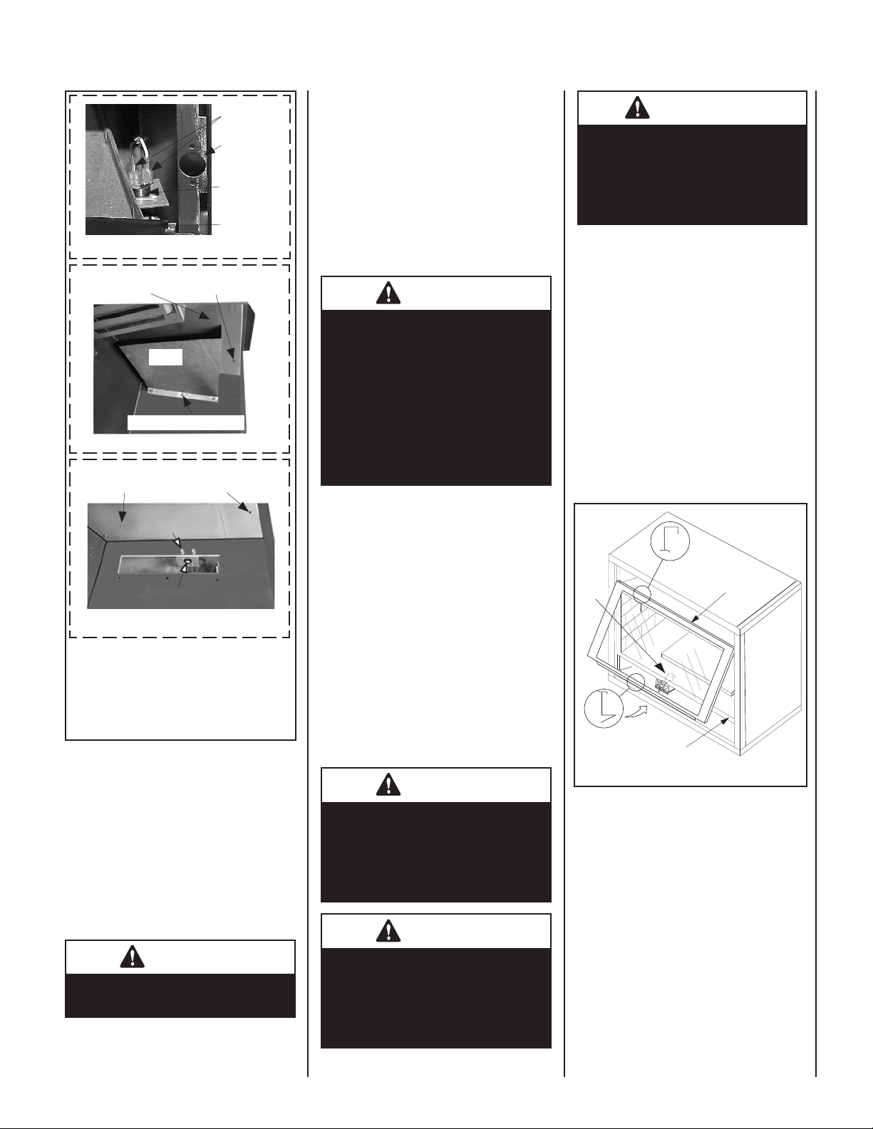
Refer to Figure 6 and remove the front glass
enclosure panel as follows:
1. Remove the top louver assembly or radiant
panel.
2. Open the hinged drop-down control compartment access panel.
3. Locate the latch at the top of the control
compartment and disengage it from the door
frame bottom Vee-fl ange, pulling down on its
handle to open it.
4. Swing the bottom of the door out and raise
it slightly to lift the top fl ange of the door frame
away from the appliance.
Top Flange
Door Frame
Latch
Glass Door
Blocked Flue Safety Limit Location
Inside View of Firebox -
Top/Right Side Intersection
Figure 5
Maintenance
The appliance and venting system should be
thoroughly inspected before initial use and at
least annually by a qualifi ed service technician.
However, more frequent periodic inspections
and cleanings should be performed by the homeowner. Homeowner must contact a qualifi ed
service technician at once if any abnormal
condition is observed.
WARNING
Turn off gas and electrical power
before servicing the appliance.
During this appliance checkout and adjustment period, a potential safety hazard exists
- EXERCISE EXTREME CAUTION to prevent
the occurrence of any burn injuries from the
exposed fl ames or hot surfaces. Also note,
that while the front glass enclosure panel is
removed, the fl ame appearance will appear to
be smaller than normal.
WARNING
Handle the glass with extreme care!
Tempered glass is susceptible to
damage (scratches, for example)
– Handle glass door (glass enclosure
panel) gently while reinstalling it.
WARNING
Do not attempt to substitute the materials used on this door, or replace
cracked or broken glass with any
materials other than those provided
by the appliance manufacturer.
Bottom Vee-flange
Door Frame
Figure 6
To install the front glass enclosure panel,
proceed as follows:
1. Retrieve the glass door frame. Visually
inspect the gasket on the backside of the
panel. The gasket surface must be clean,
free of irregularities and seated fi rmly.
2. Position the door frame in front of the fi rebox
opening and engage the top fl ange over the
lip at the top of the fi rebox opening.
3. Swing the door down and back. Ensure the
gasket seats evenly as the door draws shut.
Engage the Vee-fl ange at the bottom of the
door with the latch and close the latch to
secure the door.
4. Reinstall the top louver assembly or radiant
panel.
Firebox Floor
NOTE: DIAGRAMS & ILLUSTRATIONS ARE NOT TO SCALE.
7
Burner Adjustments
SIT Millivolt Appliance Checkout
Electronic Appliance Checkout
Note - The air shutter for the burner primary
air opening is factory-set. Do not adjust the
factory-set position. The factory-set position
is shown in Figure 7.
Burner Air Shutter Adjustment
Setscrew - Factory Located in the
Natural Gas Position; Relocate Set
Screw for LP/Propane Gas in the
Alternate Position. See Table for
Air Shutter Openings for these
Setscrew Locations.
Venturi
Air Shutter
Main Burner Factory Air Shutter
Opening Setting - Inches (millimeter)
Model Natural
Gas
MPB-3328 Fully Closed
MPB-3530 Fully Closed
MPB-4035 Fully Closed
MPB-4540 Fully Closed
Propane
Gas
3/16"
(4.76 mm)
3/16"
(4.76 mm)
3/16"
(4.76 mm)
3/16"
(4.76 mm)
The pilot fl ame should be steady, not lifting
or fl oating. Flame should be blue in color with
traces of orange at the outer edge.
The top 3/8" (10 mm) at the pilot generator
(thermopile) and the top 1/8" min (tip) of the
quick drop out thermocouple should be engulfed
in the pilot fl ame. The fl ame should project 1"
(25 mm) beyond the hood at all three ports
(Figure 8).
To light the burner, refer to the lighting instructions on Pages 18 and 19.
SIT MILLIVOLT PILOT ASSEMBLY
Proper Pilot Flame Appearance
Igniter Rod
3/8" Min.
(9 mm)
Thermocouple
Pilot
Nozzels
Figure 8
Hood
Thermopile
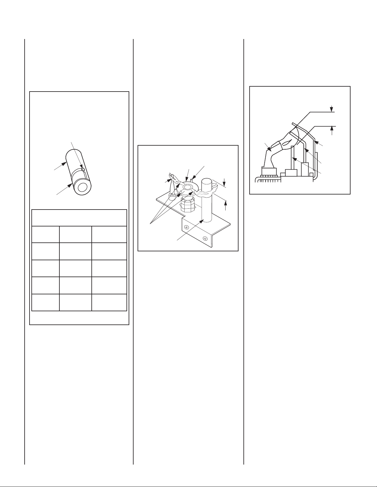
To light the burner, refer to the lighting instructions on Pages20 and 21. Ensure the igniter
lights the pilot. The pilot fl ame should engulf
the fl ame sensor as shown in Figure 9.
ELECTRONIC PILOT ASSEMBLY
Proper Pilot Flame Appearance
Proper Flame
Adjustment
Pilot
Nozzels
3/8" to 1/2"
(9 -13 mm)
Ground
Electrode
Flame Rod
Hot Surface
Igniter
Figure 9
With proper care and maintenance, your appliance will provide many years of enjoyment. If
you should experience any problem, fi rst refer
to the trouble shooting guide in this manual.
If problem persists, contact your Lennox
distributor.
Figure 7
8
NOTE: DIAGRAMS & ILLUSTRATIONS ARE NOT TO SCALE.
Log Placement
WARNING
Logs get very hot and will remain
hot up to one hour after gas supply
is turned off. Handle only when
logs are cool. Turn off all electricity
to the appliance before you install
grate and logs.
WARNING
This appliance is not meant to burn
wood. Any attempt to do so could
cause irreparable damage to your
appliance and prove hazardous to
your safety.
WARNING
The size and position on the log set
IS Critical to give your appliance a
safe, reliable and attractive fl ame
pattern. Any attempt to use a different log set in the fi replace will
void the Warranty and will result in
incomplete combustion, sooting,
and poor fl ame quality.
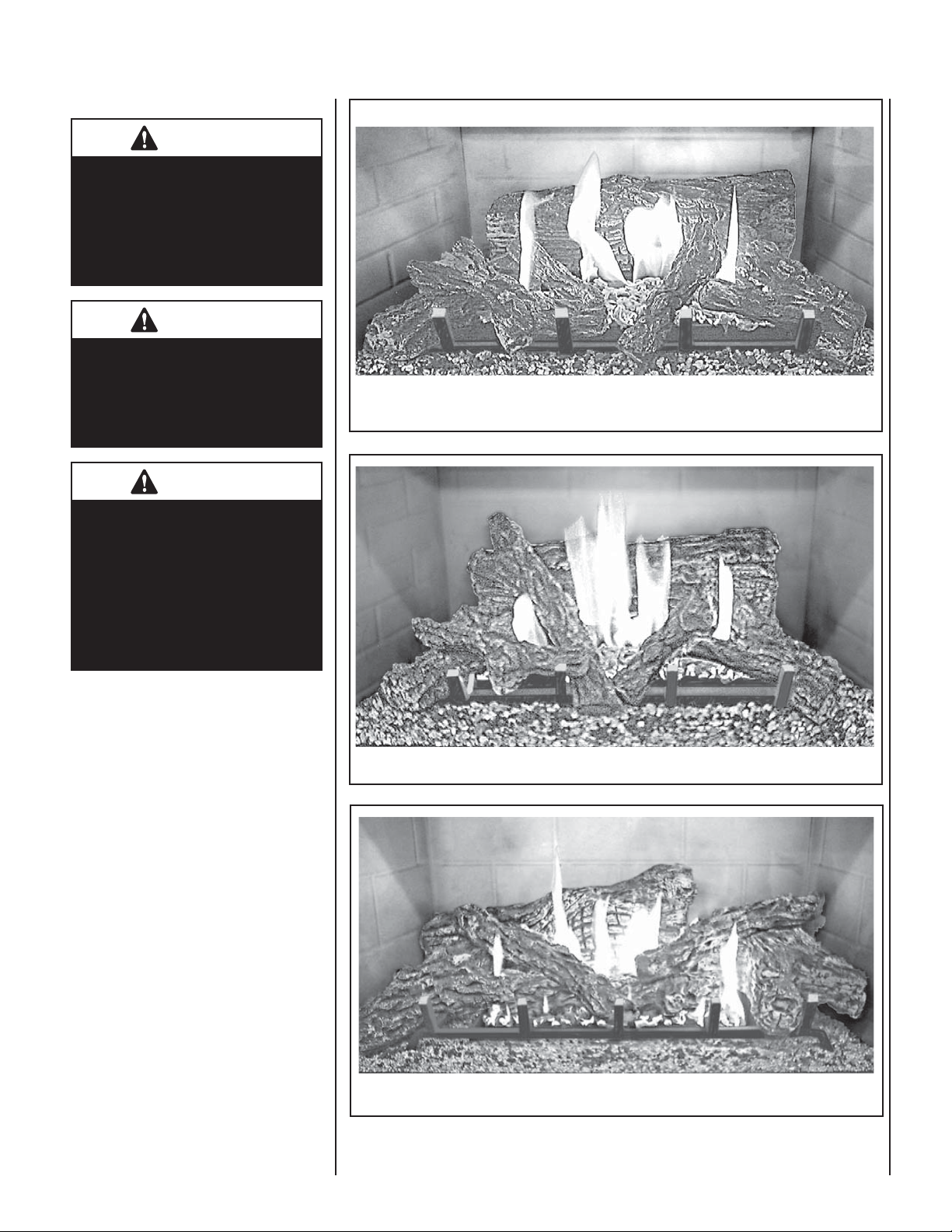
Figure 10
Burner Flame Appearance - Model MPB-3328
Initial Installation Considerations
The packaged logs are located within the fi rebox.
The decorative volcanic stone and glowing
embers are packaged separately in plastic bags
located in the control area of the fi replace.
If the logs are being installed for the fi rst time,
the following paragraphs apply:
DO NOT attempt to install the logs until the appliance installation has been completed, the gas
line connected and tested for leaks and the initial
burner operation has been checked out.
Proper twig placement is critical to prevent sooting. Twigs should be placed in the gaps between
the fl ame peaks and should be positioned so
that at no time they impinge the fl ames.
Step 1. Remove the appliance front door.
Step 2. Remove the log set from the interior
of the fi replace.
Step 3. Remove the logs from their packaging.
Handle logs carefully to prevent breakage.
Step 4. MPB-4035 & MPB-4540 Models
- Remove the restraining strap from the grate
tines. Ensure the grate is fully inserted into
the holes on the fi rebox rear panel and over
the indents on the fi rebox fl oor.
Figure 11
Figure 12
NOTE: DIAGRAMS & ILLUSTRATIONS ARE NOT TO SCALE.
Burner Flame Appearance - Model MPB-3530
Burner Flame Appearance - Model MPB-4035 & MPB-4540
9
 Loading...