

LG MDS902V, MDS902S, MDS902W, MDV902-D5U, MDV902-X5U Owner's Manual
...
Please read this manual carefully before operating your set.
Retain it for future reference.
MDV902(ENG)_MFL36762908
CD - R/RW
KARAOKE MINI HOME THEATER
OWNER’S MANUAL
MODEL : MDV902
MDV902-A5U/ D5U/ X5U
MDS902V, MDS902W, MDS902S
USB
2
Safety Precautions
This lightning flash with arrowhead symbol within an
equilateral triangle is intended to alert the user to
the presence of uninsulated dangerous voltage
within the product’s enclosure that may be of
sufficient magnitude to constitute a risk of electric
shock to persons.
The exclamation point within an equilateral triangle
is intended to alert the user to the presence of
important operating and maintenance (servicing)
instructions in the literature accompanying the
appliance.
CAUTION: Do not block any ventilation openings. Install in
accordance with the manufacturer's instructions.
Slots and openings in the cabinet are provided for ventilation
and to ensure reliable operation of the product and to protect it
from over heating.
The openings should be never be blocked by placing the product on a bed, sofa, rug or other similar surface. This product
should not be placed in a built-in installation such as a bookcase or rack unless proper ventilation is provided or the manufacturer's instruction have been adhered to.
CAUTION:
This Product employs a Laser System.
To ensure proper use of this product, please read this owner’s
manual carefully and retain for future reference, should the unit
require maintenance, contact an authorized service locationsee service procedure.
Use of controls, adjustments or the performance of procedures
other than those specified herein may result in hazardous
radiation exposure.
To prevent direct exposure to laser beam, do not try to open
the enclosure. Visible laser radiation when open. DO NOT
STARE INTO BEAM.
CAUTION: The apparatus shall not be exposed to water,
dripping or splashing and that no objects filled with liquids,
such as vases, shall be placed on the apparatus.
CAUTION:
VISIBLE AND INVISIBLE LASER RADIATION WHEN OPEN
AND INTERLOCKS DEFEATED
CAUTION concerning the Power Cord
Most appliances recommend they be placed upon a dedicated circuit;
That is, a single outlet circuit which powers only that appliance
and has no additional outlets or branch circuits. Check the
specification page of this owner's manual to be certain.
Do not overload wall outlets. Overloaded wall outlets, loose or
damaged wall outlets, extension cords, frayed power cords, or
damaged or cracked wire insulation are dangerous. Any of
these conditions could result in electric shock or fire.
Periodically examine the cord of your appliance, and if its
appearance indicates damage or deterioration, unplug it, discontinue use of the appliance, and have the cord replaced with
an exact replacement part by an authorized servicer.
Protect the power cord from physical or mechanical abuse,
such as being twisted, kinked, pinched, closed in a door, or
walked upon. Pay particular attention to plugs, wall outlets, and
the point where the cord exits the appliance.
CAUTION
RISK OF ELECTRIC SHOCK
DO NOT OPEN
WARNING: TO REDUCE THE RISK
OF ELECTRIC SHOCK
DO NOT REMOVE COVER (OR BACK)
NO USER-SERVICEABLE PARTS INSIDE
REFER SERVICING TO QUALIFIED SERVICE
PERSONNEL.
WARNING: TO REDUCE THE RISK OF FIRE OR ELECTRIC SHOCK, DO NOT EXPOSE THIS PRODUCT TO
RAIN OR MOISTURE.
Power Save Mode - OPTIONAL
You can set up the unit into an economic power save
mode.
In power-on status, press and hold POWER
(/[) button for about 3 seconds.
- Nothing is displayed in the display window when the
unit is turned off.
To cancel, press
/
[
(
POWER), CLOCK, TIMER or
PLAY MODE(DEMO).
INTRODUCTION
3
Table of Contents
Introduction
Safety Precautions. . . . . . . . . . . . . . . . . . . . . . . . . . . . . . . . 2
Table of Contents. . . . . . . . . . . . . . . . . . . . . . . . . . . . . . . . . 3
Before Use . . . . . . . . . . . . . . . . . . . . . . . . . . . . . . . . . . . . . 3
Front Panel/ Rear Panel. . . . . . . . . . . . . . . . . . . . . . . . . . . . 4
Remote Control . . . . . . . . . . . . . . . . . . . . . . . . . . . . . . . . . . 5
Preparation
Connections . . . . . . . . . . . . . . . . . . . . . . . . . . . . . . . . . . . 6-9
Before Operation. . . . . . . . . . . . . . . . . . . . . . . . . . . . . . 10-16
Operation
Operation with DVD and Video CD . . . . . . . . . . . . . . . . 17-18
Operation with Audio CD and MP3/WMA Disc . . . . . . . . . . 19
Operation with JPEG Disc . . . . . . . . . . . . . . . . . . . . . . . . . 20
Operation with DivX Disc . . . . . . . . . . . . . . . . . . . . . . . . . 21
Operation with RADIO . . . . . . . . . . . . . . . . . . . . . . . . . 22-23
Operation with TAPE . . . . . . . . . . . . . . . . . . . . . . . . . . . . . 24
Recording . . . . . . . . . . . . . . . . . . . . . . . . . . . . . . . . . . . . . 24
Operation with KARAOKE . . . . . . . . . . . . . . . . . . . . . . 25-28
Reference
Troubleshooting . . . . . . . . . . . . . . . . . . . . . . . . . . . . . . . . . 29
Language Code List. . . . . . . . . . . . . . . . . . . . . . . . . . . . . . 30
Area Code List. . . . . . . . . . . . . . . . . . . . . . . . . . . . . . . . . . 30
Specifications
About Symbols
About the symbol display
“ ” may appear on the TV screen during operation.
This icon means the function explained in this owner’s
manual is not available on that specific DVD video disc.
About the disc symbols for instructions
A section of which title has one of the following symbols
is applicable only to the disc represented by the symbol.
DVD
Video CDs
Audio CDs
MP3 file
WMA file
JPEG file
DivX file
About the symbols for instructions
Caution
Caution Indicates hazards likely to cause harm to the
unit itself or other material damage.
Note
Note Indicates special operating features of this unit.
TTip
ip Indicates tips and hints to make the task easier.
DivX
JPEG
WMA
MP3
ACD
VCD
DVD
Before Use
Playable Discs
DVD
(8 cm / 12 cm disc)
Video CD (VCD)
(8 cm / 12 cm disc)
Audio CD
(8 cm / 12 cm disc)
In addition, this unit can play a DVD±R, DVD±RW,
SVCD, and CD-R or CD-RW that contains audio titles,
MP3, WMA, JPEG or DivX files.
Notes
Notes
• Depending on the conditions of the recording equipment or the CD-R/RW (or DVD±R/RW) disc itself,
some CD-R/RW (or DVD±R/RW) discs cannot be
played on the unit.
• Do not attach any seal or label to either side (the
labeled side or the recorded side) of a disc.
•
Do not use irregularly shaped CDs (e.g., heart-shaped
or octagonal). It may result in malfunctions.
Note
Note on DVDs and Video CDs
Some playback operations of DVDs and Video CDs
may be intentionally fixed by software manufacturers. As
this unit plays DVDs and Video CDs according to disc
content designed by the software manufacturer, some
playback features of the unit may not be available or
other functions may be added.
Refer also to the instructions supplied with the DVDs
and Video CDs. Some DVDs made for business purposes may not be played on the unit.
Regional Code
This unit has a regional code printed on the rear of the
unit. This unit can play only DVD discs labelled as the
same as the rear of the unit or “ALL”.
Notes on Regional Codes
• Most DVD discs have a globe with one or more numbers in it clearly visible on the cover. This number
must match your unit’s regional code or the disc cannot play.
• If you try to play a DVD with a different regional code
from your player, the message “Check Regional
Code” appears on the TV screen.
4
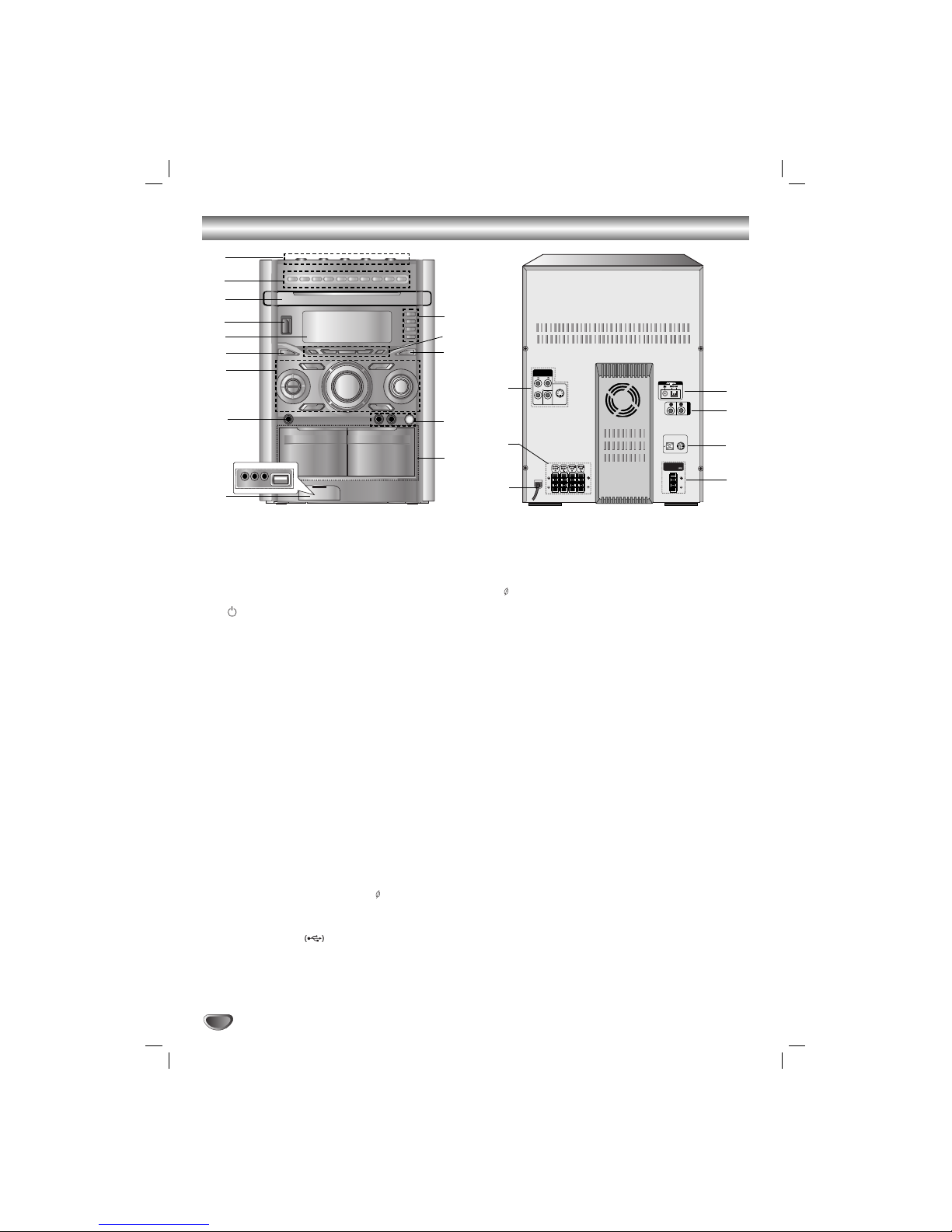
Front Panel/ Rear Panel
WOOFER SYSTEM
AUX IN
SUB WOOFER
SPEAKER
R
L
COMPONENT
YMONITOR
OUT
S-VIDEO
OUT
VIDEO OUT
(PROGRESSIVE SCAN)
REAR
R (8 )
REAR
L (8 )
CENTER
(8 )
FRONT
R (4 )
FRONT
L (4 )
WOOFER
PRE-OUT
AUX IN
MIC ANT.
C
H
A
N
N
E
L
1. • DISC SKIP button
• Z OPEN/CLOSE button
•
DISC SELECT buttons (DISC1, DISC2,DISC3)
2. NUMERIC buttons (0-9)
3. DISC DOOR
4. (
/
[
)POWER button
5. DISPLAY WINDOW
6. XDSS button
7. • (PROG./MEMO.)PROGRAM/MEMORY button
• (zREC/PAUSE[])
RECORD/RECORD PAUSE button
• (PLAY MODE) PLAY MODE/DEMO button
• (SET/CD[]/(RDS-OPTIONAL)/AM-NOISE button
• FUNCTION SELECT buttons
(TUNER, KARAOKE/DVD,TAPE, USB,AUX/AV)
• VOLUME knob
• EQ button
• SURROUND button
• (MP3 OPT) MP3 OPTIMIZER button
• USER EQ button
MULTI JOG.
• MANUAL TUNING
• CD SKIP(.SKIP>)
• CLOCK ADJUST
• (b-KEY CON-#) KEY CONTROL
8. HEADPHONE Jack (PHONES): 6.3 mm
9. • GAME LINK connector
(VIDEO IN, AUDIO L/R)
• USB connector
10. Z PUSH EJECT position (TAPE 1)
Z PUSH EJECT position (TAPE 2)
11.• MIC VOLUME knob (MIC VOL.)
• MIC Jacks (MIC1/ MIC2):
6.3 mm : OPTIONAL
12. OAO button
13. • AUTO TUNING DOWN/UP button
REWIND/ FAST FORWARD(
bbbb/BBBB
)/
TEMPO DOWN(-)/TEMPO UP(+)/SCAN(-/+)
• PRESET DOWN/UP button
• STOP/CLEAR(x) button
• BACKWARD PLAY (bb) button - OPTIONAL
• FORWARD PLAY (BB) button
14.
• CLOCK button
• TIMER button
• (ST./MONO) STEREO/MONO,
(NOR.DUBB.) NORMAL DUBBING button
• CD SYNCHRO RECORDING (CD SYNC.),
HIGH DUBBING (HI-DUBB.) button
15. • COMPONENT VIDEO OUT
(PROGRESSIVESCAN) connector (Y P
B PR)
• MONITOR OUT Jack
• S-VIDEO OUT Jack
16.
SPEAKER Terminal
17. POWER CORD
18. SUBWOOFER SPEAKER Terminal
19. WOOFER SYSTEM Terminal
20. (AUX IN) AUXILIARY INPUT Jack
21. (FM/AM) ANTENNA Jack
1
3
4
5
6
7
8
9
10
11
12
13
2
14
18
16
15
17
19
20
21
5
INTRODUCTION
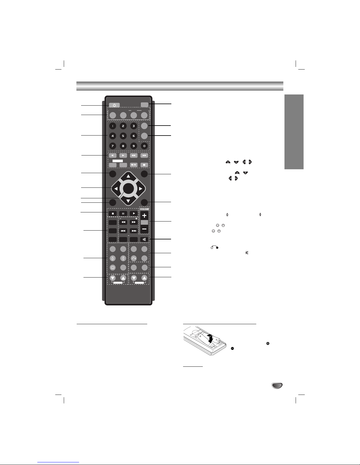
Remote Control
Remote Control Operation Range
Point the remote control toward the remote sensor and
press the buttons.
• Distance: About 23 ft (7 m) from the front of the
remote sensor
• Angle: About 30° in each direction of the front of the
remote sensor
Remote control battery installation
Detach the battery cover on
the rear of the remote control, and insert two R03 (size
AAA) batteries with and
aligned correctly.
Caution
Caution
Do not mix old and new batteries. Never mix different
types of batteries (standard, alkaline, etc.).
1. POWER button
2. FUNCTION SELECT buttons
(TUNER/BAND,DVD/KARAOKE, AUX, USB)
3. NUMERIC buttons (0-9)
4. TAPE FUNCTION buttons
• REVERSE PLAY (
F
)
• PLAY (
G
)
• REWIND/ FAST FORWARD PLAY (
FF/GG
)
• TAPE 1-2 SELECT buttons (1-TAPE-2)
• RECORD/ RECORD PAUSE (z/[])
• TAPE STOP (x)
5. SET UP button
6. • ARROW buttons ( / / / )
(Selects an option in the menu.)
• PRESET (-/+) buttons ( / )
• TUN. (-/+) buttons ( / )
7. SELECT/ENTER button
8. MENU button
(Use the MENU button to display the menu screen
included on DVD video discs.)
9. STOP (x), PAUSE([])/ STEP, PLAY (
G
) buttons
10. PROG./MEMO., REPEAT, REPEAT A-B buttons
11.
EQ ,OAO, FEMALE( ),
AUDIO/MALE( ),
SUBTITLE (S-TITLE), SHADOW,CLEAR buttons
12. ECHO VOL. ( / ) buttons
13. MIC VOL. ( / ) buttons
14. RDS, PTY buttons (OPTIONAL)
15.
XDSS ,SURROUND(SURR.)
, ZOOM,
RETURN ( ) buttons
16. • MARKER, SEARCH, MUTE(
) buttons,
• SCAN (
FF/GG
)/TEMPO (-/+),/ KEY CON
(b/#)/,SKIP (./>)
17. VOLUME -/+ buttons
18. TITLE button
(Use the TITLE button to display the title screen
included on DVD video discs.)
19. DISPLAY button
20. DIMMER button
21. SLEEP button
22. DISC SKIP (D.SKIP) button
PRESET +
PRESET -
SETUP
TEMPO
MENU
REPEAT
MARKER SEARCH
REPEAT A-B
PROG./MEMO.
PROG./MEMO.
OAO
XDSS
SURR.
ZOOM
EQ
AUDIO
S-TITLE
RETURN
RDS PTY
CLEAR
TITLE
DISPLAY
SLEEP
DIMMER
AUX
DVD/
KARAOKE
KARAOKE
POWER
/ENTER
SELECT
MUTE
TUNER/BAND
USB
D.SKIP
D.SKIP
STOP PLAY
PAUSE/STEP
ECHO VOL.
MIC VOL.
TUN. - TUN. +
1 - TAPE - 2
SHADOW
KEY CON - #
b -
1
6
5
4
3
2
8
9
21
20
18
16
17
19
7
10
12
13
15
11
22
14
Connections
6
Make one of the following connections, depending on
the capabilities of your existing equipment.
TTips
ips
• Depending on your TV and other equipment you wish
to connect, there are various ways you could connect
the
unit
. Use one of the connections described below.
• Please refer to the manuals of your TV, VCR, Stereo
System or other devices as necessary to make the
best connections.
Caution
Caution
•
Make sure the unit is connected directly to the TV.
Select the correct AV input on your TV.
• Do not connect your
unit
to TV via your VCR. The
DVD image could be distorted by the copy protection
system.
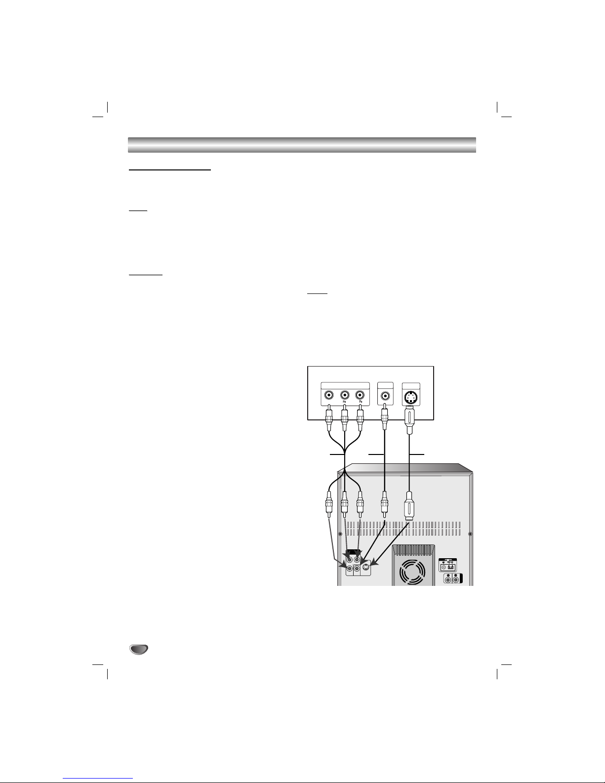
Video connection
Connect the MONITOR OUT jack from the
unit
to the
VIDEO IN jack on the TV using the video cable supplied
(V).
S-Video connection
Connect the S-VIDEO OUT jack on the
unit
to the S-
VIDEO IN jack on the TV using the S-Video cable (S).
Component Video (Color Stream®) connection
Connect the COMPONENT VIDEO OUT (PROGRESSIVE SCAN) (Y P
B PR) jacks from the
unit
to the corre-
sponding jacks on the TV using a Y P
B PR cable (C).
Progressive Scan (Color Stream®pro) connection
• If your television is a high-definition or “digital ready”
television, you may take advantage of this
unit
’s
progressive scan output for higher video resolution.
• If your TV does not accept the Progressive Scan format, the picture will appear scrambled if you try
Progressive Scan on the
unit
.
Connect the COMPONENT VIDEO OUT (PROGRESSIVE SCAN) (Y P
B PR) jacks from the
unit
to the corre-
sponding jacks on the TV using an optional Y P
B PR
cable (C).
Note
Note
Set the Progressive to “On” in the Setup menu for progressive signal, see the page 14.
Connecting to a TV
WOOFER SYSTEM
AUX IN
SUB WOOFER
SPEAKER
R
L
COMPONENT
Pr
Pb
Y MONITOR
OUT
S-VIDEO
OUT
VIDEO OUT
(PROGRESSIVE SCAN)
Y
COMPONENT VIDEO /
PROGRESSIVE SCAN INPUT
L
VIDEO
IN
S-VIDEO
IN
Rear of TV
S
V
C
7
Connections
PREPARATION
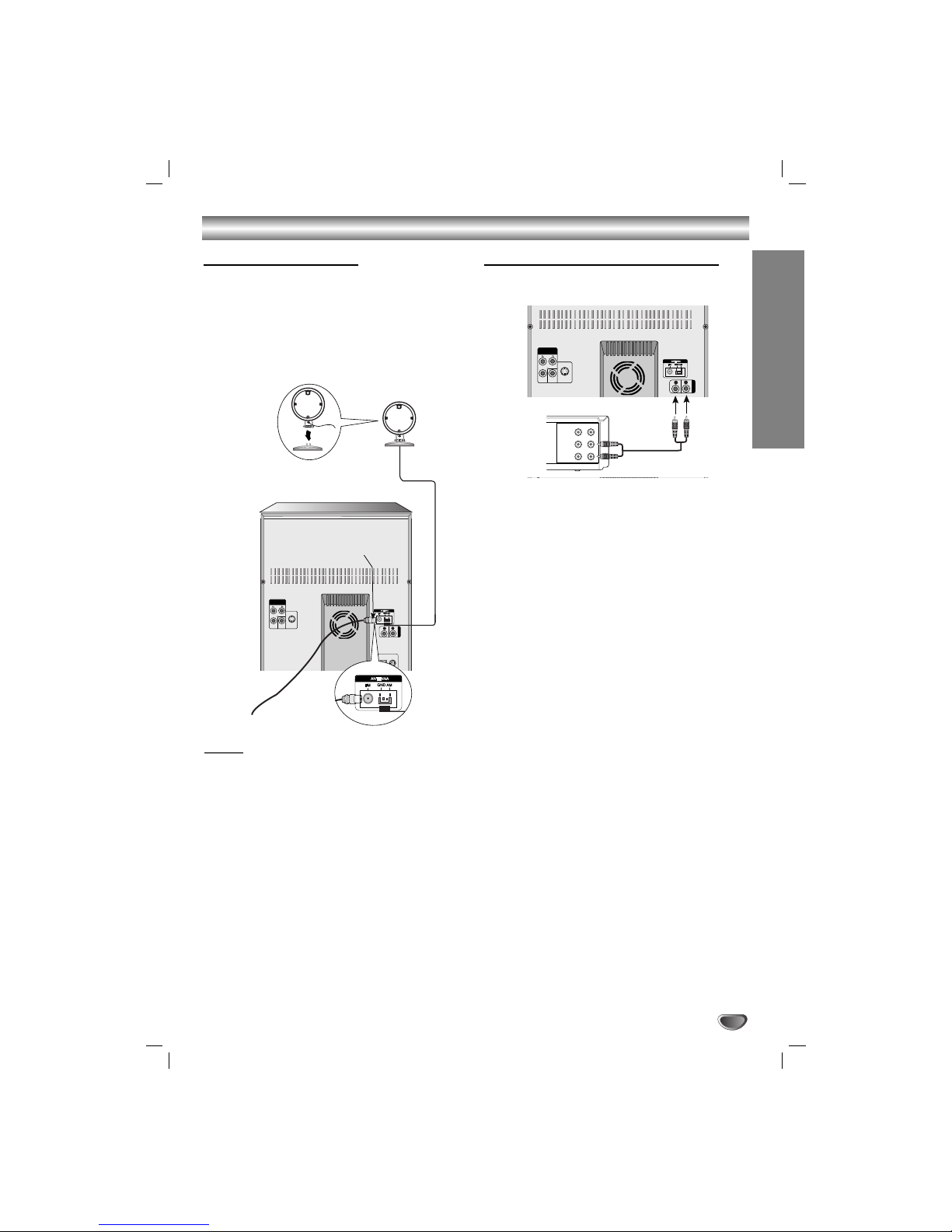
Connecting to Antenna
Connect the supplied FM/AM antennas to listen to the
radio.
• Connect the AM loop antenna to the AM antenna
connector.
• Connect the FM wire antenna to the FM antenna
connector.
Notes
Notes
•To prevent noise pickup, keep the AM loop antenna
away from the unit and other component.
• Be sure to fully extend the FM wire antenna.
• After connecting the FM wire antenna, keep it as
horizontal as possible.
WOOFER SYSTEM
AUX IN
SUB WOOFER
SPEAKER
R
L
COMPONENT
Y MONITOR
OUT
S-VIDEO
OUT
VIDEO OUT
(PROGRESSIVE SCAN)
AM(MW) loop
antenna (aerial)
(Supplied)
For AM(MW) reception, connect the
loop antenna (aerial) to the terminal
marked AM
FM wire
antenna
(supplied)
Connecting to Auxiliary Equipment
You can use VCR or other unit connected to the AUX
connector.
1
Connect a VCR or auxiliary device, etc to the
AUX connector.
22
Press the AUX button on the front panel or the
remote control until the “AUX” indicator is
displayed in the display window.
WOOFER SYSTEM
AUX IN
SUB WOOFER
SPEAKER
R
L
COMPONENT
Y MONITOR
OUT
S-VIDEO
OUT
VIDEO OUT
(PROGRESSIVE SCAN)
VIDEO
OUTIN
AUDIO (L)
AUDIO (R)
VCR (or Auxiliary
Device, etc)
To AUDIO IN
To AUDIO OUT
Connections
8
USB Memory,
MP3 Player (or
Memory Card
Reader, etc.)
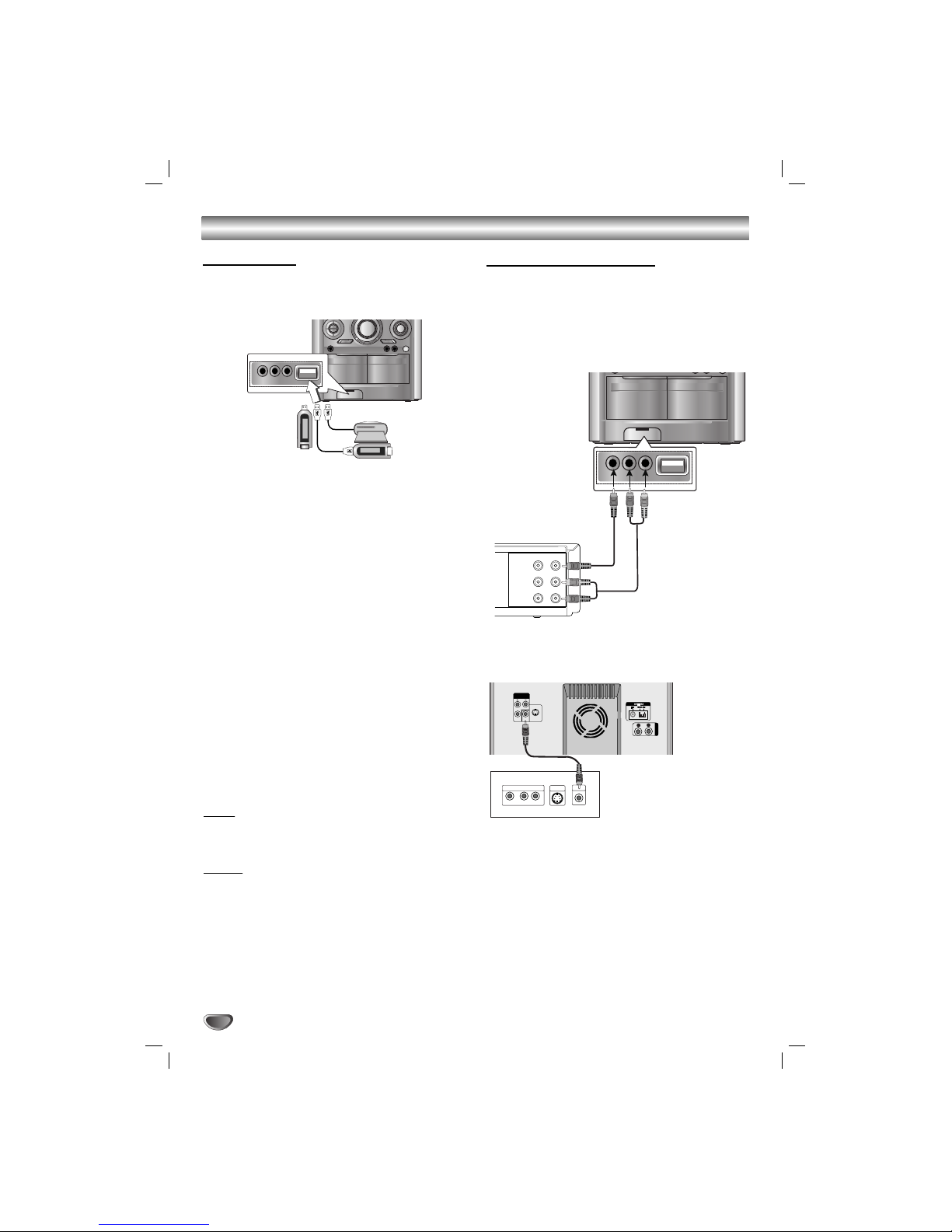
Connecting to GAME LINK
Optional Equipment Connections
Connnection of the TV/Monitor, Video Game or
DVD, etc.
1
Connect the video/audio output connector of auxiliary device to the GAME LINK INPUT (VIDEO IN,
AUDIO L/R) connector.
22
Connect the video input connector of TV/Monitor to
the MONITOR OUT connector.
33
Press A/V button on the front panel or AUX button
on the remote control to select A/V (Audio/ Video)
function.
“A/V” will be shown in the display window.
VIDEO
OUTIN
AUDIO (L)
AUDIO (R)
Video Game or DVD, etc
To AUDIO OUT
To AUDIO IN
To VIDEO OUT
To VIDEO IN
WOOFER SYSTEM
AUX IN
SUB WOOFER
SPEAKER
R
L
Y
Pb
Pr
COMPONENT VIDEO /
PROGRESSIVE SCAN INPUT
L
VIDEO
IN
S-VIDEO
IN
COMPONENT
Y MONITOR
OUT
S-VIDEO
OUT
VIDEO OUT
(PROGRESSIVE SCAN)
Rear of TV
USB Function
You can enjoy the media files such as tunes
(MP3/WMA) saved in an MP3 player or USB memory
by connecting the storage device to the USB port of
this unit.
Basic Playback
1
Connect the USB device to the USB connector of your
unit.
2
Press USB to select USB function.
“CHECKING” appears in the display window, and then the
total number of files is displayed.
3
Press PLAYBB.
In addition, you can also play using the
NUMERIC buttons.
To Remove the USB from the unit
1
Choose the other functions except USB
function in order to remove the USB.
2
. Remove the USB from the unit.
Note
Note
Besides Basic Playback, if you want to operate other
functions, see the CD Playback section.
Notes
Notes
• Do not extract the USB device in operating.
•Aback up demands to prevent a data damage.
• If you use a USB extension cable or USB hub, the
USB device might not be recognized.
•Adevice using NTFS file system is not supported.
(Only FAT (16/32) file system is supported.)
• The USB function of this unit does not support all
USB devices.
• Digital camera and mobile phone are not supported.
• This unit is not supported when the total number of
files is 1000 or more.
Compatible Devices
1
Devices which require additional program installation when you have connected it to a computer, are
not supported.
22
MP3 Player : Flash type MP3 player.
T
he MP3 player requiring installation of a driver is
not supported.
33
USB Flash Drive : Devices that support USB2.0 or
USB1.1.
9
Connections
Front speaker
(Right)
WOOFER SYSTEM
AUX IN
SUB WOOFER
SPEAKER
R
L
COMPONENT
Y MONITOR
OUT
S-VIDEO
OUT
VIDEO OUT
(PROGRESSIVE SCAN)
Front speaker
(Left)
Surround speaker
Subwoofer
Surround speaker
(Right)
(Left)
Notes
Notes
• Be sure to match the speaker cable to the appropriate terminal on the components: + to + and – to –. If the
cables are reversed, the sound will be distorted and will lack base.
• If you use front speakers with low maximum input rating, adjust the volume carefully to avoid excessive output on
the speakers.
• Connect the Front Left/Right speaker correctly. If it is reversed, the sound may be distorted.
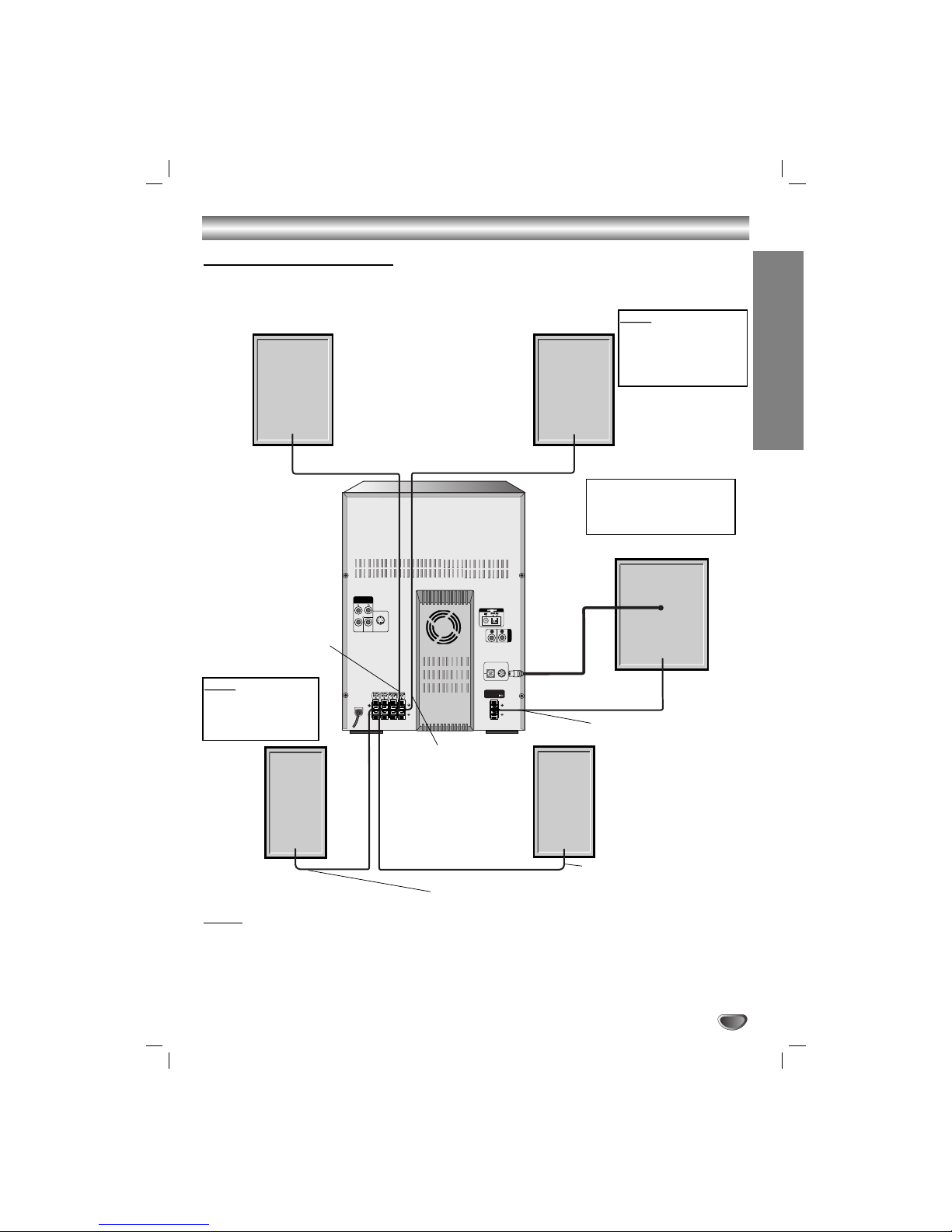
Speaker System Connection
Connect the speakers using the supplied speaker cables by matching the colors of the terminals and those of the
cords. To obtain the best possible surround sound, adjust the speaker parameters (distance, level, etc.).
PREPARATION
Note
Note
Do not place the surround speakers by
TV.
If you hear the sound from
the subwoofer, press the
SUBWOOFER ON/OFF button to turn the subwoofer on.
Note
Note
If TV screen becomes
discolored do not place
front speakers within
30cm from TV.
Wire band color : Red
Wire band color
:White
Wire band color :
Orange
Wire band color : Blue
Wire band color : Gray

Before Operation
10
Volume Adjustment
•Turn VOLUME knob clockwise to increase the sound
level, or counterclockwise to decrease it.
• Press VOLUME + to increase the sound level, or use
VOLUME - to decrease it on the remote control.
MUTE
Press MUTE to , press again to restore. You can mute
your unit in order, for example, to answer the telephone,
“” indicator flashes in the display window.
To cancel it , press mute again or volume (-/+) on the
remote control.
Headphone Jack
Connect a stereo headphone plug ( 6.3mm) into the
headphone jack.
The speakers are automatically disconnected when you
plug in the headphones (not supplied).
EQUALIZER Effect
You can choose 12 fixed sound impressions and adjust
the BASS, MIDDLE and TREBLE.
-You can select a desired sound mode by using EQ
button on the front panel or remote control.
When a sound mode passes by with the left side from
the right, press EQ
NORMAL → POP → CLASSIC → ROCK → DRAMA
→JAZZ → SALSA → MUSICAL → SAMBA →
ADVENTURE → PUMP → EXTREME → NORMAL...
-You can select a mode by using USER EQ button on
the front panel.
1.
Press the USER EQ button for more than 1 second.
“
BASS 0” will appear in the display window.
2. Turn the MULTI JOG.
clockwise or
counterclockwise to set the sound level you want.
(MIN, -4 ~ +4, MAX steps).
3.Select the BASS, MIDDLE or TREBLE you want by
pressing the
USER EQ
buttons on the front panel.
4. To cancel the USER MODE, press the USER EQ button until “USER MODE OFF” appears
.
XDSS (Extreme Dynamic Sound System)
Press XDSS to reinforce treble and bass.
- The “XDSS ON” indicator lights up.
To cancel it press XDSS again.
- The “XDSS NORMAL” indicator lights up.
OAO (Orientation Acoustic Optimizer)
ON/OFF
Press OAO to reinforce the original sound.
- The “OAO ON” indicator lights up.
To cancel it press OAO again.
- The “OAO NORMAL” indicator lights up.
MP3 Optimizer
This function is optimized for compressible MP3/WMA
file. It is improves the bass sound to make sweet sound.
Each time you press MP3 OPT the setting changes in
the following order.
MP3-OPT ON y MP3-OPT NORMAL
SURROUND Effect
You can select a desired surround mode by using SURROUND button on the front panel or SURR. button on
the remote control.
When a surround mode passes by with the left side
from the right, press SURROUND or SURR..
SURROUND OFF → CINEMA → EALA → TUNNEL →
HALL → THEATER → VOCAL → CHURCH → DISCO
→ SURROUND OFF...
DIMMER
This function turns the LED (Light-emitting diode) of
front panel off and darkens the display window by half in
power-on status.
Press DIMMER once. The LED (Light-emitting diode) of
front panel is turned off.
If you press it once more, the display window will be
darken by half. To cancel it, press the button again.
DEMO
Press DEMO in power off state to demonstrate the
function in the display window.
To cancel it, press (
/
[
)POWER or DEMO again.
During demonstration in power-on status, you can cancel it by using the CLOCK, TIMER buttons.
Selecting the sound system
You can enjoy different sounds by selecting the sound
mode you want.
Turn MODE SELECT knob on the subwoofer to select
the sound mode.
LINK ON → SURROUND 1 → SURROUND 2
Using the subwoofer
You can use the sound of the subwoofer to enhance the
bass.
Press SUBWOOFER ON/OFF on the subwoofer to turn
on the subwoofer.
SUB_WOOFER ON y SUB_WOOFER OFF
 Loading...