

LG MCV903 Diagram
MODEL : MCV903(MCS903F,MCS903S,MCS903W,MCS903AW)
SERVICE MANUAL
MINI Hi-Fi SYSTEM
SERVICE MANUAL
CAUTION
BEFORE SERVICING THE UNIT, READ THE “SAFETY PRECAUTIONS” IN THIS MANUAL.
MODEL : MCV903
(MCS903F,MCS903S,MCS903W,MCS903AW)
Website http://biz.lgservice.com
Internal Use Only
Copyright © 2008 LG Electronics. Inc. All right reserved.
Only for training and service purposes
LGE Internal Use Only
1-1
❍ SECTION 1. GENERAL
•
SERVICING PRECAUTIONS . . . . . . . . . . . . . . . . . . . . . . . . . . . . . . . . . . . . . . . . . . . . . . . . 1-2
• ESD PRECAUTIONS . . . . . . . . . . . . . . . . . . . . . . . . . . . . . . . . . . . . . . . . . . . . . . . . . . . . . . 1-4
• LOCATION OF USERS CONTROLS . . . . . . . . . . . . . . . . . . . . . . . . . . . . . . . . . . . . . . . . . . 1-5
• SPECIFICATION . . . . . . . . . . . . . . . . . . . . . . . . . . . . . . . . . . . . . . . . . . . . . . . . . . . . . . . . . 1-7
• USB DOWNLOAD GUIDE . . . . . . . . . . . . . . . . . . . . . . . . . . . . . . . . . . . . . . . . . . . . . . . . . . 1-8
❍ SECTION 2. EXPLODED VIEWS
•
CABINET AND MAIN FRAME SECTION . . . . . . . . . . . . . . . . . . . . . . . . . . . . . . . . . . . . . . . 2-1
• TAPE DECK MECHANISM EXPLODED VIEW . . . . . . . . . . . . . . . . . . . . . . . . . . . . . . . . . . . 2-3
• CD MECHANISM EXPLODED VIEW . . . . . . . . . . . . . . . . . . . . . . . . . . . . . . . . . . . . . . . . . . 2-7
•
SPEAKER EXPLODED VIEW. . . . . . . . . . . . . . . . . . . . . . . . . . . . . . . . . . . . . . . . . . . . . . . . 2-9
• PACKING ACCESSORY
VIEW . . . . . . . . . . . . . . . . . . . . . . . . . . . . . . . . . . . . . . . . . . . . . . 2-13
❍ SECTION 3. AUDIO ELECTRICAL PART
•
AUDIO ELECTICAL TROUBLESHOOTING GUIDE. . . . . . . . . . . . . . . . . . . . . . . . . . . . . . . . 3-1
• INTERNAL BLOCK DIAGRAM OF ICs . . . . . . . . . . . . . . . . . . . . . . . . . . . . . . . . . . . . . . . . 3-17
• WIRING DIAGRAM. . . . . . . . . . . . . . . . . . . . . . . . . . . . . . . . . . . . . . . . . . . . . . . . . . . . . . . 3-29
• BLOCK DIAGRAMS . . . . . . . . . . . . . . . . . . . . . . . . . . . . . . . . . . . . . . . . . . . . . . . . . . . . . . 3-31
• SCHEMATIC DIAGRAMS . . . . . . . . . . . . . . . . . . . . . . . . . . . . . . . . . . . . . . . . . . . . . . . . . . 3-35
• PRINTED CIRCUIT DIAGRAMS . . . . . . . . . . . . . . . . . . . . . . . . . . . . . . . . . . . . . . . . . . . . . 3-59
❍ SECTION 4.
CD
ELECTRICAL PART
•
CD ELECTICAL TROUBLESHOOTING GUIDE . . . . . . . . . . . . . . . . . . . . . . . . . . . . . . . . . . 4-1
• WAVEFORMS OF MAJOR CHECK POINT. . . . . . . . . . . . . . . . . . . . . . . . . . . . . . . . . . . . . . 4-3
• SCHEMATIC DIAGRAMS . . . . . . . . . . . . . . . . . . . . . . . . . . . . . . . . . . . . . . . . . . . . . . . . . . . 4-5
• PRINTED CIRCUIT DIAGRAMS . . . . . . . . . . . . . . . . . . . . . . . . . . . . . . . . . . . . . . . . . . . . . 4-11
❍ SECTION 5. REPLACEMENT PARTS LIST
•
REPLACEMENT PARTS LIST . . . . . . . . . . . . . . . . . . . . . . . . . . . . . . . . . . . . . . . . . . . . . . . 5-1
[CONTENTS]

1-2
NOTES REGARDING HANDLING OF THE PICK-UP
1. Notes for transport and storage
1) The pick-up should always be left in its conductive bag until immediately prior to use.
2) The pick-up should never be subjected to external pressure or impact.
2. Repair notes
1) The pick-up incorporates a strong magnet, and so should never be brought close to magnetic materials.
2) The pick-up should always be handled correctly and carefully, taking care to avoid external pressure and
impact. If it is subjected to strong pressure or impact, the result may be an operational malfunction and/or
damage to the printed-circuit board.
3) Each and every pick-up is already individually adjusted to a high degree of precision, and for that reason
the adjustment point and installation screws should absolutely never be touched.
4) Laser beams may damage the eyes!
Absolutely never permit laser beams to enter the eyes!
Also NEVER switch ON the power to the laser output part (lens, etc.) of the pick-up if it is damaged.
5) Cleaning the lens surface
If there is dust on the lens surface, the dust should be cleaned away by using an air bush (such as used for
camera lens). The lens is held by a delicate spring. When cleaning the lens surface, therefore, a cotton swab
should be used, taking care not to distort this.
6) Never attempt to disassemble the pick-up.
Spring by excess pressure. If the lens is extremely dirty, apply isopropyl alcohol to the cotton swab. (Do not
use any other liquid cleaners, because they will damage the lens.) Take care not to use too much of this
alcohol on the swab, and do not allow the alcohol to get inside the pick-up.
SERVICING PRECAUTIONS
SECTION 1. GENERAL
Copyright © 2008 LG Electronics. Inc. All right reserved.
Only for training and service purposes
LGE Internal Use Only
Copyright © 2008 LG Electronics. Inc. All right reserved.
Only for training and service purposes
LGE Internal Use Only
1-3
NOTES REGARDING COMPACT DISC PLAYER REPAIRS
1. Preparations
1) Compact disc players incorporate a great many ICs as well as the pick-up (laser diode).These components
are sensitive to, and easily affected by, static electricity. If such static electricity is high voltage, components
can be damaged, and for that reason components should be handled with care.
2) The pick-up is composed of many optical components and other high-precision components. Care must be
taken, therefore, to avoid repair or storage where the temperature of humidity is high, where strong magnetism is present, or where there is excessive dust.
2. Notes for repair
1) Before replacing a component part, first disconnect the power supply lead wire from the unit
2) All equipment, measuring instruments and tools must be grounded.
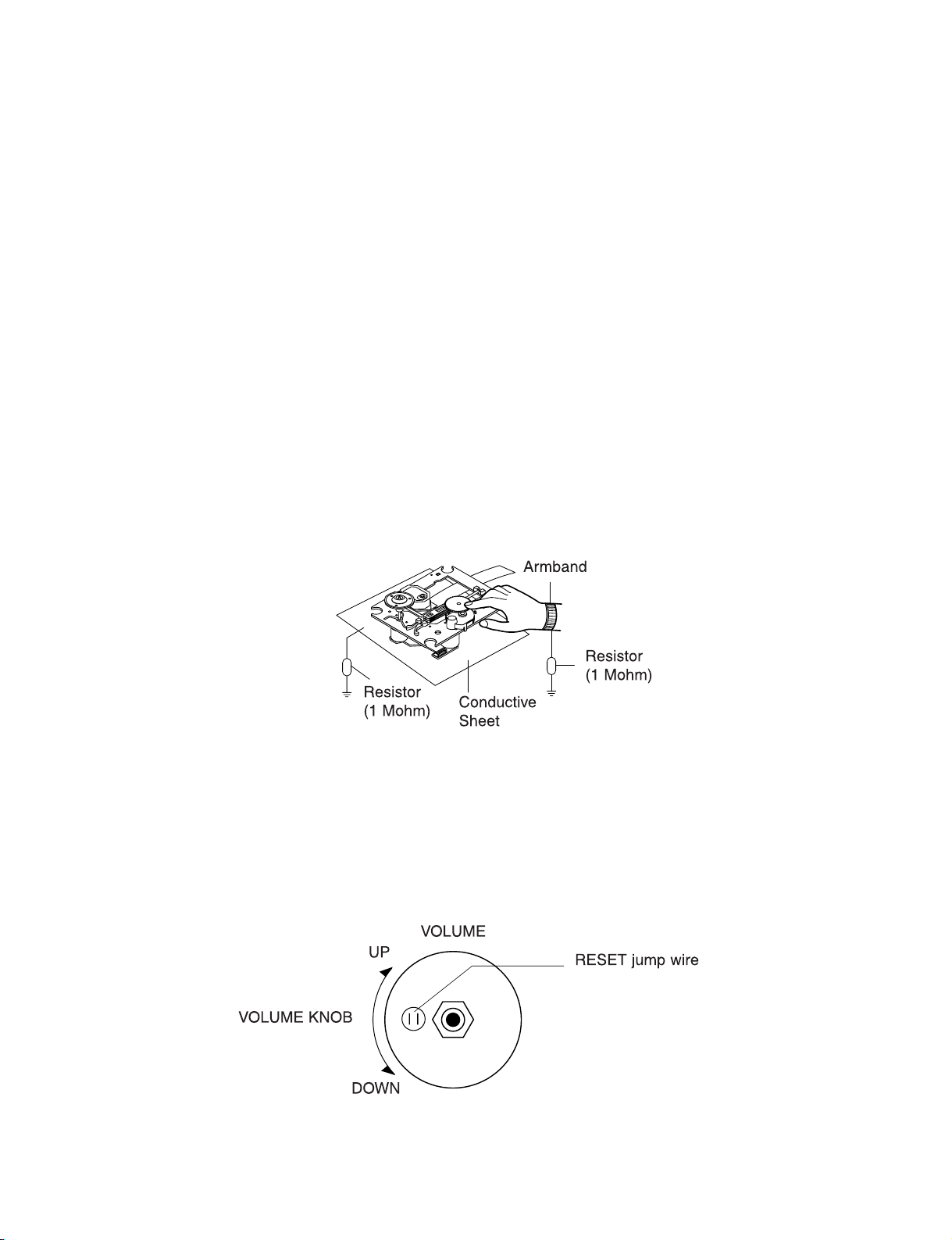
3) The workbench should be covered with a conductive sheet and grounded.
When removing the laser pick-up from its conductive bag, do not place the pick-up on the bag. (This is
because there is the possibility of damage by static electricity.)
4) To prevent AC leakage, the metal part of the soldering iron should be grounded.
5) Workers should be grounded by an armband (1MΩ)
6) Care should be taken not to permit the laser pick-up to come in contact with clothing, in order to prevent
static electricity changes in the clothing to escape from the armband.
7) The laser beam from the pick-up should NEVER be directly facing the eyes or bare skin.
CLEARING MALFUNCTION
You can reset your unit to initial status if malfunction occur(button malfunction, display, etc.).
Using a pointed good conductor(such as driver), simply short the RESET jump wire on the inside of
the volume knob for more than 3 seconds.
If you reset your unit, you must reenter all its settings(stations, clock, timer)
NOTE: 1. To operate the RESET jump wire, pull the volume rotary knob and release it.
2. If you wish to operate the RESET jump wire, it is necessary to unplug the power cord.
Copyright © 2008 LG Electronics. Inc. All right reserved.
Only for training and service purposes
LGE Internal Use Only
1-4
Electrostatically Sensitive Devices (ESD)
Some semiconductor (solid state) devices can be damaged easily by static electricity. Such components commonly are called Electrostatically Sensitive Devices (ESD). Examples of typical ESD devices are integrated circuits and some field-effect transistors and semiconductor chip components. The following techniques should be
used to help reduce the incidence of component damage caused by static electricity.
1. Immediately before handling any semiconductor component or semiconductor-equipped assembly, drain off
any electrostatic charge on your body by touching a known earth ground. Alternatively, obtain and wear a commercially available discharging wrist strap device, which should be removed for potential shock reasons prior
to applying power to the unit under test.
2. After removing an electrical assembly equipped with ESD devices, place the assembly on a conductive surface such as aluminum foil, to prevent electrostatic charge buildup or exposure of the assembly.
3. Use only a grounded-tip soldering iron to solder or unsolder ESD devices.
4. Use only an anti-static solder removal device. Some solder removal devices not classified as "anti-static" can
generate electrical charges sufficient to damage ESD devices.
5. Do not use freon-propelled chemicals. These can generate electrical charges sufficient to damage ESD
devices.
6. Do not remove a replacement ESD device from its protective package until immediately before you are ready
to install it. (Most replacement ESD devices are packaged with leads electrically shorted together by conductive foam, aluminum foil or comparable conductive materials).
7. Immediately before removing the protective material from the leads of a replacement ESD device, touch the
protective material to the chassis or circuit assembly into which the device will by installed.
CAUTION : BE SURE NO POWER IS APPLIED TO THE CHASSIS OR CIRCUIT, AND OBSERVE ALL OTHER
SAFETY PRECAUTIONS.
8. Minimize bodily motions when handing unpackaged replacement ESD devices. (Otherwise harmless motion
such as the brushing together of your clothes fabric or the lifting of your foot from a carpeted floor can generate static electricity sufficient to damage an ESD device).
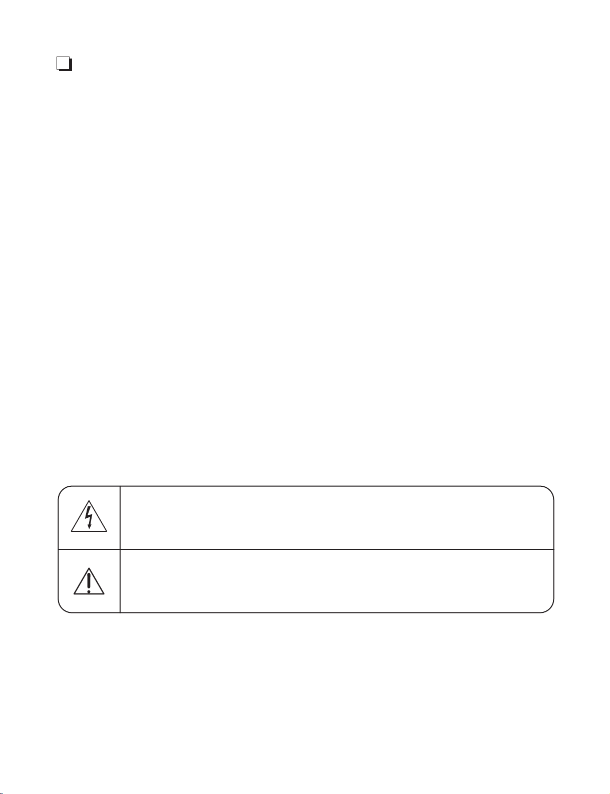
CAUTION. GRAPHIC SYMBOLS
ESD PRECAUTIONS
THE LIGHTNING FLASH WITH APROWHEAD SYMBOL. WITHIN AN EQUILATERAL TRIANGLE, IS
INTENDED TO ALERT THE SERVICE PERSONNEL TO THE PRESENCE OF UNINSULATED
“DANGEROUS VOLTAGE” THAT MAY BE OF SUFFICIENT MAGNITUDE TO CONSTITUTE A RISK OF
ELECTRIC SHOCK.
THE EXCLAMATION POINT WITHIN AN EQUILATERAL TRIANGLE IS INTENDED TO ALERT THE
SERVICE PERSONNEL TO THE PRESENCE OF IMPORTANT SAFETY INFORMATION IN SERVICE
LITERATURE.

1-5
Copyright © 2008 LG Electronics. Inc. All right reserved.
Only for training and service purposes
LGE Internal Use Only
LOCATION OF USERS CONTROLS
FRONT / BACK PANEL
• DISPLAY WINDOW
• Choose a desired CD
• TIME
• Power on/off
• CLOCK
•
To select TUNER (FM or AM) fuction
• eXtreme Dynamic Sound System
• Look for radio stations
automatically
• DEMO
• VOCAL FADE
• PORTABLE IN
• PHONES
• SET
•
OPEN/CLOSE
• Record from tape to tape
• Disc tray
• Skip to another track
• NATURAL EQ
• MIC VOL.
• Starts playback
• Stops playback or recording
• Look for radio stations
automatically
• Starts or pauses recording
• PORTABLE
• MIC 1/MIC 2
1-6
Copyright © 2008 LG Electronics. Inc. All right reserved.
Only for training and service purposes
LGE Internal Use Only
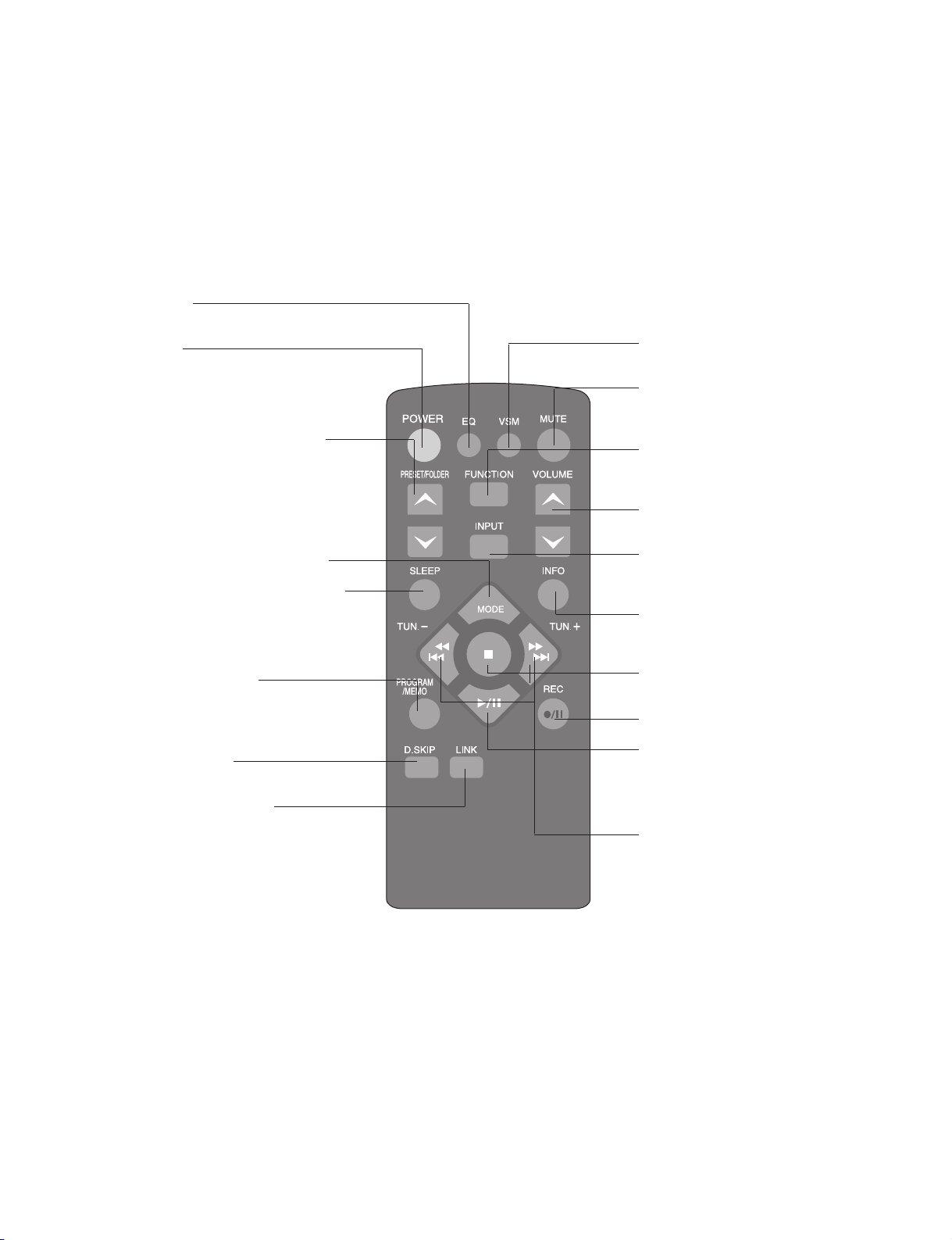
REMOTE CONTROL
• NATURAL EQ
You can choose sound impressions.
• Power on/off
Power save mode
Press POWER for longer than 3 seconds as
the device is powered on, you can move into
power save mode.
• Search for a folder of MP3/WMA files
When a CD containing MP3/WMA files in several fold-ers is being played, press
PRESET/FOLDER to select the folder you
want to play.
Choose a ‘preset number’ for a radio station
(see Listening to the radio)
• Listen to your tracks again and again
• Fall asleep while listening to your player
Press SLEEP one or more times to select
delay time between 10 and 180 minutes, after
the player will turn off.
Dimm the display light
• For storing radio stations
(see Listening to the radio)
Listen to your tracks in any order
(see Listening to the CDs)
• Choose a desired CD
(see Listening to CDs)
• Selecting the sound system
You can enjoy different sounds by selecting the
sound mode you want. Press LINK repeatedly,
the display changes in the following order,
LINK ON→SURROUND 1→SURROUND 2.
• VSM (Virtual Sound Matrix)
You can select the Virtual sound.
• Temporarily stop the sound
Press the button again to return to
the sound.
• To change the functions
Change the functions among FM,
AM, CD, TAPE.
• Control the volume when using any
function.
• To change the INPUT functions
Change the functions among USB,
PORTABLE, AUX.
• See information about your music
MP3/WMA files often come with tags. The tag
gives the Title, Artist, Album or Time information.
• Stops playback or recording
• Starts or pauses recording
• Starts or pauses playback
Improve poor FM reception
This will change the tuner from
stereo to mono and usually improve
the reception
• Select the radio station
Search for a section within a track
Play Fast backward or Forward
.

1-7
Copyright © 2008 LG Electronics. Inc. All right reserved.
Only for training and service purposes
LGE Internal Use Only
SPECIFICATIONS
General
Power supply Refer to main label.
Power consumption Refer to main label.
Net Weight 8.45 kg
External dimensions (W x H x D) 170 x 240 x 260 mm
Operating temperature 5ºC to 35ºC
Operating humidity 5% to 85 %
Tuner
FM Tuning Range 87.5 - 108.0 MHz or 65.0 - 74.0 MHz, 87.5 - 108.0 MHz
AM Tuning Range 522 - 1,620 kHz or 520 - 1,720 kHz
Amplifier
OUTPUT POWER Front : 280 W + 280 W, Surround : 140 W + 140 W,
Sub Woofer : 180 W + 180 W
T.H.D 10 %
Frequency Response 40 - 20000Hz
Signal-to-noise ratio 75dB
CD player
Frequency response 42 - 20000 Hz
Signal- to- noise ratio 75 dB
Dynamic range 80dB
Cassette tape player
F.F/REW Time 120 sec (C-60)
Frequency Response 250 - 8000 Hz
Signal to Noise Ratio 43 dB
Channel Separation 45 dB (P/B)/45 dB (R/P)
Erase Ratio 50 dB (MTT-5511)
Speakers
MCS903S MCS903F MCS903AW/MCS903W
Type
Bass Reflex 2Way 2 Speaker Bass Reflex 2Way 2 Speaker Bass Reflex 1 Way 1 Speaker
Impedance 16 Ω 8 Ω 12 Ω
Frequency Response 70 - 20000 Hz 55 - 20000 Hz 50 - 1500 Hz
Sound Pressure Level Rated
83 dB/W (1m) 86 dB/W (1m) 85 dB/W (1m)
Input Power 140 W 280 W 180 W
Max. Input Power 280 W 560 W 360 W
Net Dimensions 205 x 432 x 286 mm 270 x 432 x 326 mm 315 x 432 x 356 mm
Net Weight (1EA) 4.4 kg 8.3 kg 9.8 kg
Designs and specifications are subject to change without pior notice.
1-8
Copyright © 2008 LG Electronics. Inc. All right reserved.
Only for training and service purposes
LGE Internal Use Only
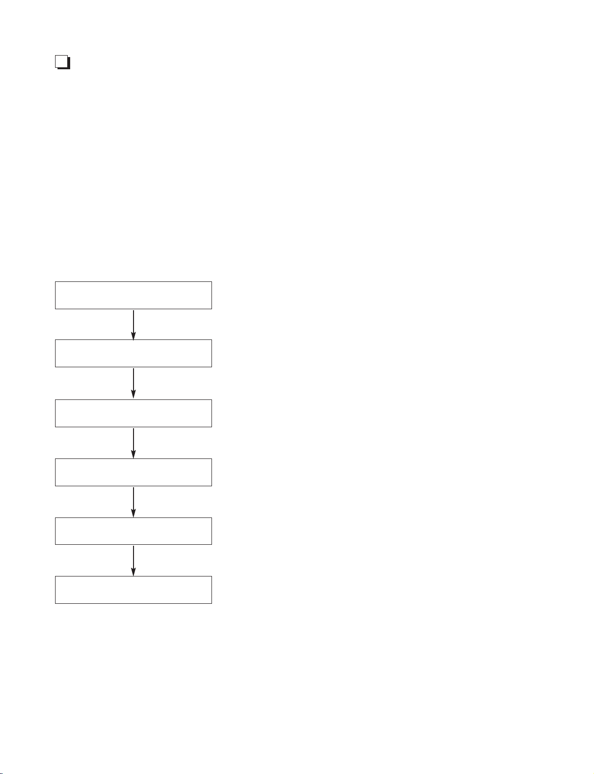
USB DOWNLOAD GUIDE
1. AUDIO USB DOWNLOAD GUIDE
Download program file name must be MCV903.HEX.mcs.
→ If security program (Water Wall) is activated on your PC, you must save the file to the USB storage
device and disable the security software then download the file to your set.
Caution: When downloading the file, you should neither unplug the USB device, change to the other
function, nor power off the device. USB device must be unplugged when the downloading
process is completed.
ON VFD DISPLAY SCREEN
NO USB
1. INSERT USB DEVICE AT USB FUNCTION
2. WHEN COMPLETED, REMOVE USB DEVICE.
READ
FIRMWARE
WRITE 00 .. 100
UPDATED
POWER OFF AUTOMATICALLY

1-9
Copyright © 2008 LG Electronics. Inc. All right reserved.
Only for training and service purposes
LGE Internal Use Only
2. CD USB DOWNLOAD GUIDE
Download program file name must be LGBOX_HA8M.mcs.
→ If security program (Water Wall) is activated on your PC, you must save the file to the USB storage
device and disable the security software then download the file to your set.
Caution: When downloading the file, you should neither unplug the USB device, change to the other
function, nor power off the device. USB device must be unplugged when the downloading
process is completed.
ON VFD DISPLAY SCREEN
NO USB
1. INSERT USB DEVICE AT USB FUNCTION
2. WHEN COMPLETED, REMOVE USB DEVICE.
READ
FIRMWARE
FINISH
UPDATED
POWER OFF MANUALLY

1-10
Copyright © 2008 LG Electronics. Inc. All right reserved.
Only for training and service purposes
LGE Internal Use Only
Copyright © 2008 LG Electronics. Inc. All right reserved.
Only for training and service purposes
LGE Internal Use Only
2-1 2-2
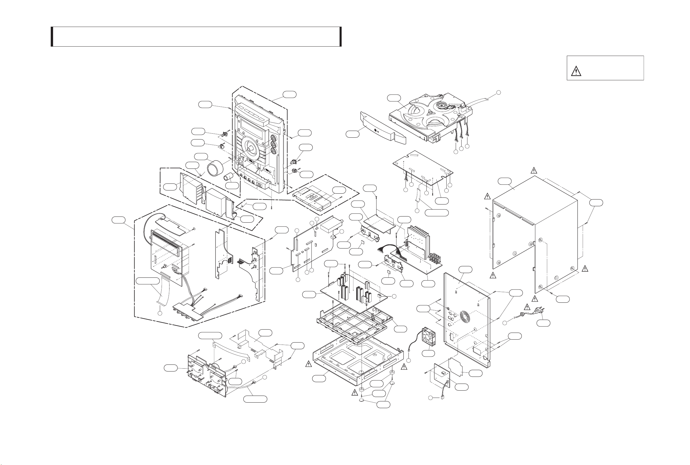
1. CABINET AND MAIN FRAME SECTION
SECTION 2. EXPLODED VIEWS
NOTES) THE EXCLAMATION POINT WITHIN AN
EQUILATERAL TRIANGLE IS INTENDED
TO ALERT THE SERVICE PERSONNEL
TO THE PRESENCE OF IMPORTANT
SAFETY INFORMATION IN SERVICE
LITERATURE.
A43
CABLE3
270
FRONT
H
A00
265
274
451
288
259
CABLE1
260
451
274
271
F
CABLE2
289
G
A46
451
250
H
F
451
451
266
265
A47
D
A26
275
C
B
A
CD
D
L
A
272
451
A51
K
CABLE4
J
451
302
453
I
K
AIN
M
C
B
A41
280
451
283
453
L
G
SMPS
451
283
278
301
E
A56
451
451
451
E
305
276
451
262
I
285
277
281
451
SUB
A52
J
282
2-3 2-4
Copyright © 2008 LG Electronics. Inc. All right reserved.
Only for training and service purposes
LGE Internal Use Only
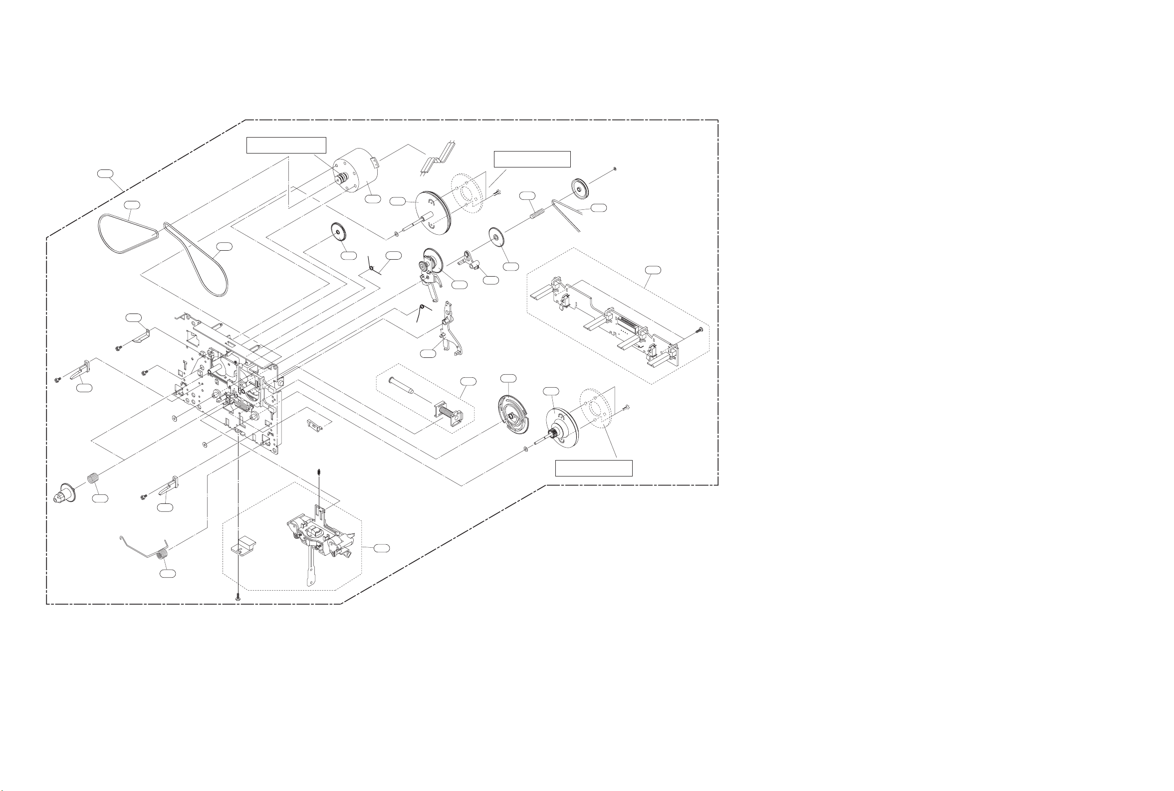
TAPE DECK MECHANISM EXPLODED VIEW
1. TAPE DECK MECHANISM (A/R & A/S : RIGHT A/R DECK)
009
A00
001
003
BRASS MOTOR PULLEY MAYBE CHANGED
FOR WOW FLUTTER WHEN NECESSAR
002
Y
006
037
007
008
016
015
022
RING FW MAYBE ADDED
FOR WOW FLUTTER WHEN NECESSAR
019
018
017
023
025
Y
020
A01
011
009
013
A02
RING FW MAYBE ADDED
FOR WOW FLUTTER WHEN NECESSAR
Y

2. TAPE DECK MECHANISM (A/R & A/S : LEFT A/S DECK)
2-5 2-6
Copyright © 2008 LG Electronics. Inc. All right reserved.
Only for training and service purposes
LGE Internal Use Only
019
003
009
A00
007
008
016
017
022
018
023
015
020
RING FW MAYBE ADDED
FOR WOW FLUTTER WHEN NECESSAR
024
Y
011
009
013
A03

CD MECHANISM EXPLODED VIEW
2-7 2-8
Copyright © 2008 LG Electronics. Inc. All right reserved.
Only for training and service purposes
LGE Internal Use Only
159
416
A26
151
A32
416
177
166
417
167
165
164
417
422
440
441
172
163
170
419
168
155
417
162
153
173
418
421
156
A35
188
189
190
418
181
A30
421
184
187
175
186
185
417

2-9
Copyright © 2008 LG Electronics. Inc. All right reserved.
Only for training and service purposes
LGE Internal Use Only
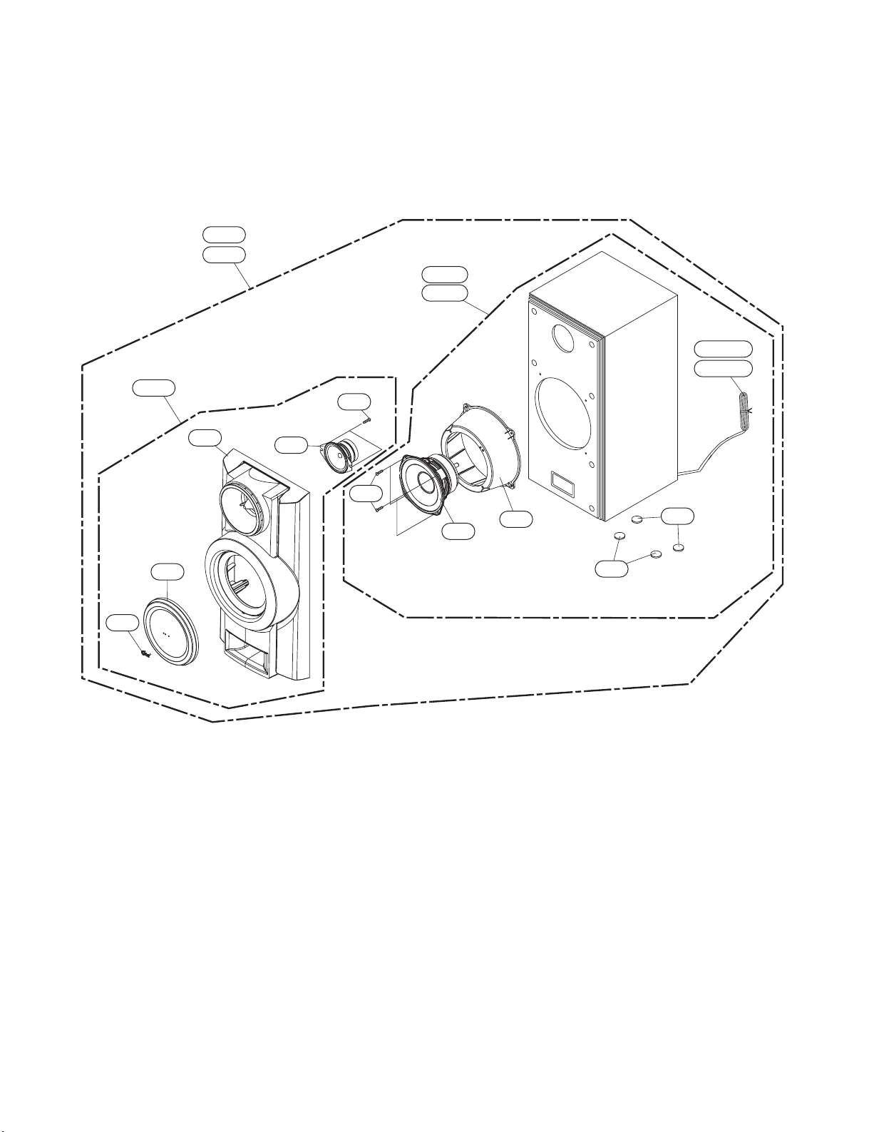
• FRONT SPEAKER (MCS903F)
SPEAKER EXPLODED VIEW
A80L
A80R
A80BL
A80BR
858
A80A
852
854
853
851
850
856
855
857
WIRE80
WIRE81
860
859
860
2-10
Copyright © 2008 LG Electronics. Inc. All right reserved.
Only for training and service purposes
LGE Internal Use Only
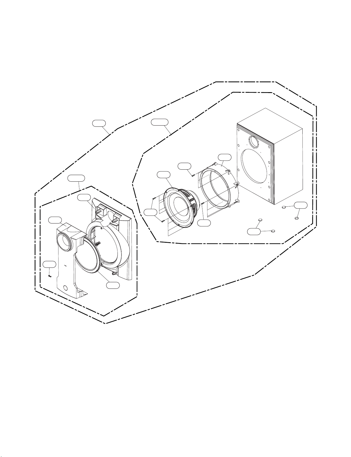
• REAR SPEAKER (MCS903S)
A60R
A60R
A60A
653
A60BL
A60BR
WIRE60
WIRE61
654
651
650
652
655
656
657
658
658
2-11
Copyright © 2008 LG Electronics. Inc. All right reserved.
Only for training and service purposes
LGE Internal Use Only
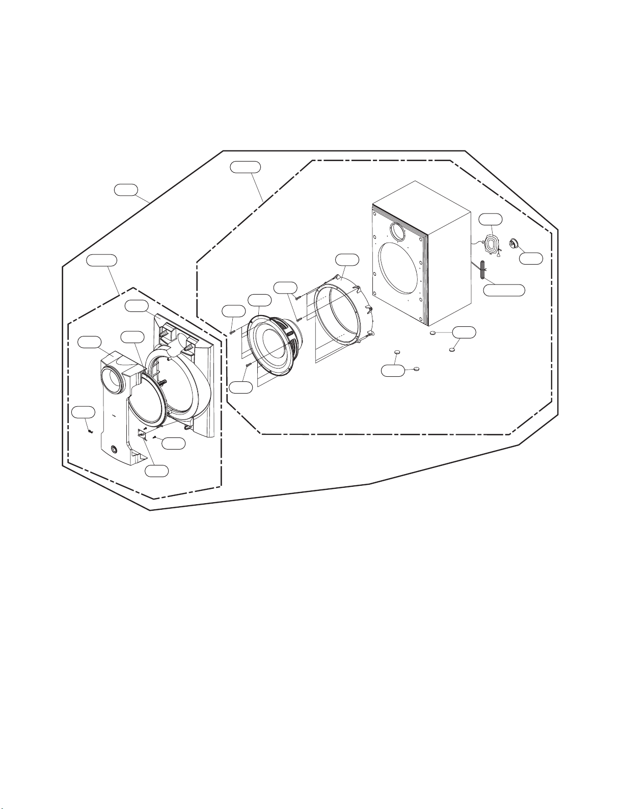
• PASSIVE SUBWOOFER (MCS903W)
952
953
950
A90
951
958
958
956
956
957
A90B
A90A
954
955
2-12
Copyright © 2008 LG Electronics. Inc. All right reserved.
Only for training and service purposes
LGE Internal Use Only
• PASSIVE SUBWOOFER (MCS903AW)
A70B
A70
761
753
752
A70A
750
751
754
755
757
757
756
758
759
760
WIRE70
762
762
2-13
Copyright © 2008 LG Electronics. Inc. All right reserved.
Only for training and service purposes
LGE Internal Use Only
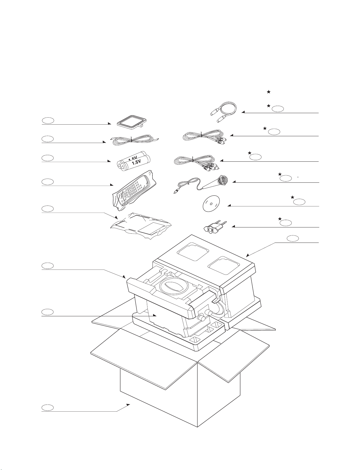
• PACKING ACCESSORY
VIEW
824 ANTENNA LOOP
825 ANTENNA
808 Battery
OPTIONAL PARTS
806 Cable, Coaxial
811
Plug Ass'y, 1Way
Plug Ass'y, 2Way(Yellow)
812
Remote Control
900
Instruction Ass'y
801
803
Packing
Bag
804
826 Microphone
832
DISC
830 AC Adaptor
803
Packing
Box
802

2-14
Copyright © 2008 LG Electronics. Inc. All right reserved.
Only for training and service purposes
LGE Internal Use Only
3-1
Copyright © 2008 LG Electronics. Inc. All right reserved.
Only for training and service purposes
LGE Internal Use Only
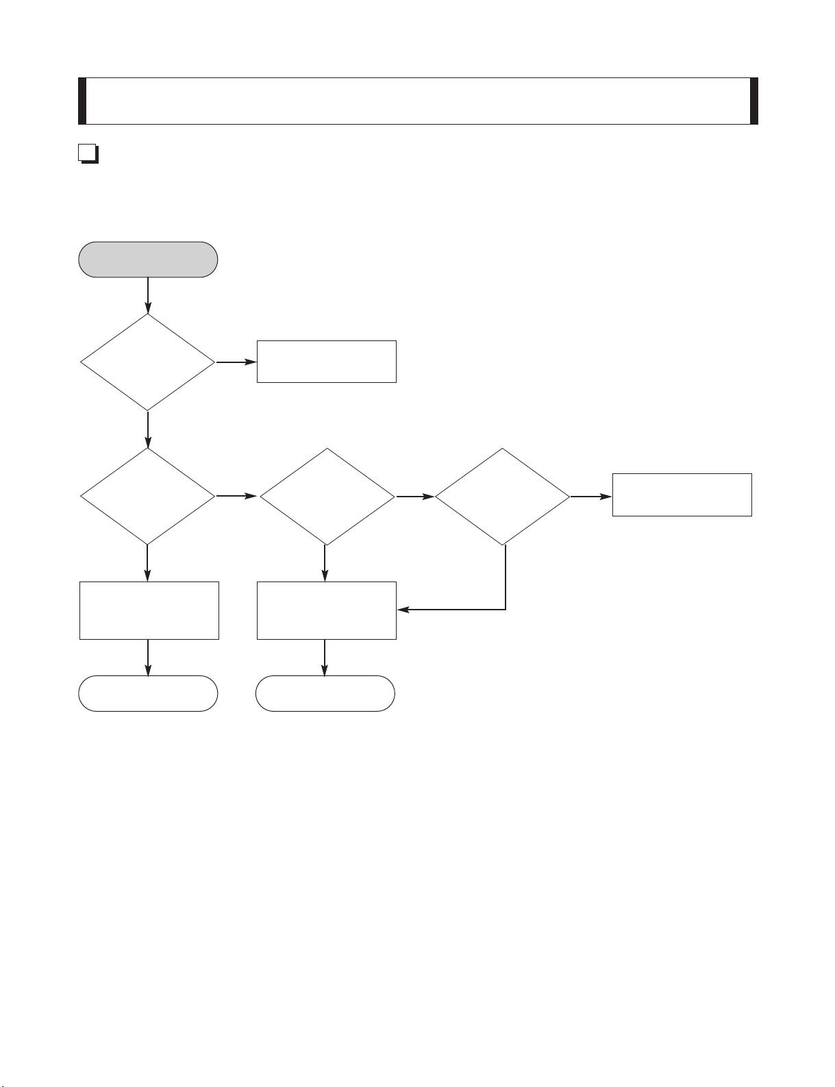
1. MICOM PART CHECK I
OK OK
NO
NO NO
Replace the related
part
Is IC101 KIA7042
output 4.3V?
YES
YES
YES YES
YES YES
Check the IC100
87F5NC8A 4
PIN power
YES
Refer to SMPS
Troubleshooting.
MICOM PART
HECK I
Check
CN710 7PIN
P- SENS
NO
Is IC101
KIA7042
5V?
Is IC101
KIA7042
input 5V?
Check the
related part of IC101
KIA7042
AUDIO ELECTRICAL TROUBLESHOOTING GUIDE
SECTION 3. AUDIO
ELECTRICAL PART
3-2
Copyright © 2008 LG Electronics. Inc. All right reserved.
Only for training and service purposes
LGE Internal Use Only
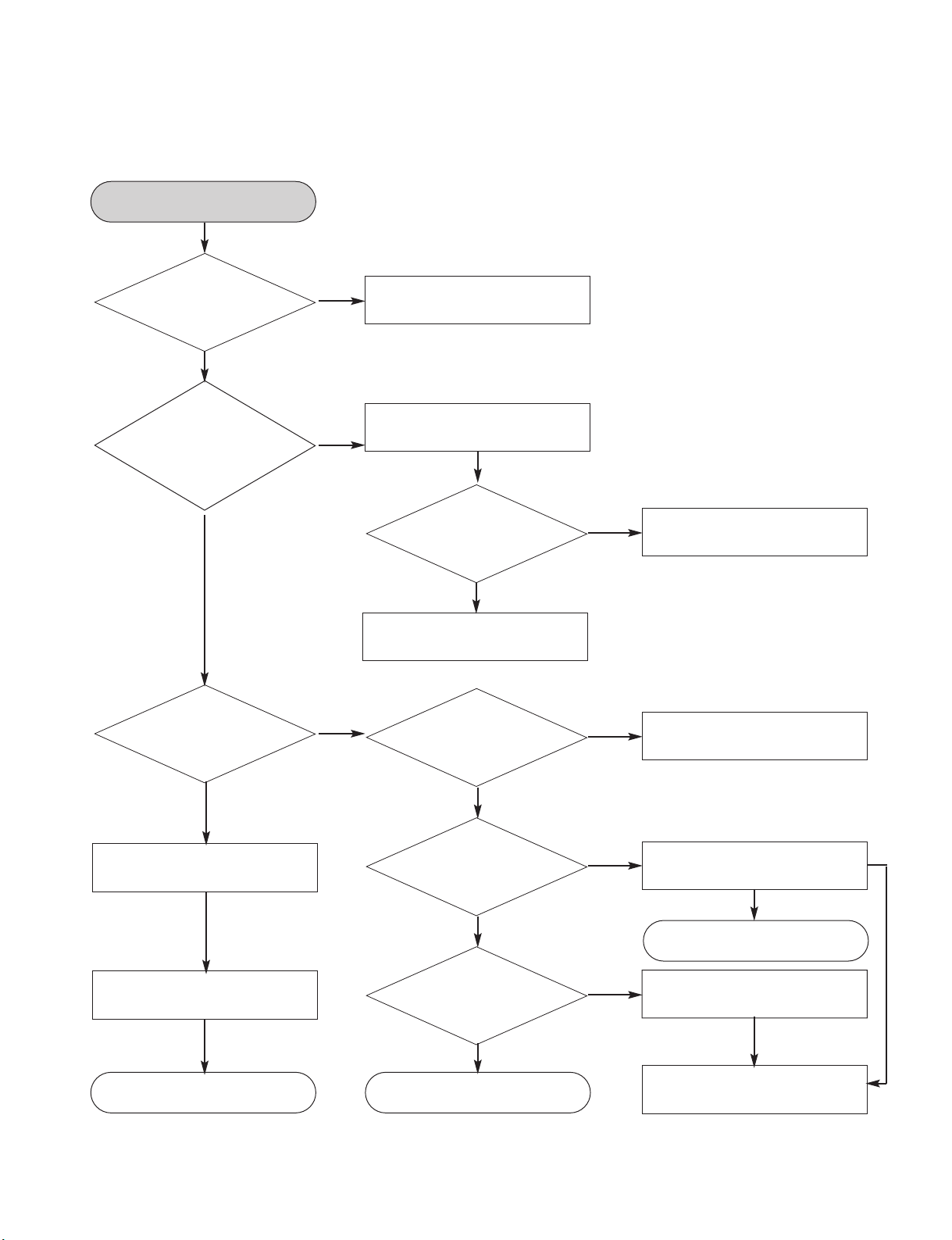
2. MICOM PART CHECK II
NO
YES
YES
YES
YES
YES
Refer to SMPS
Troubleshooting.
NO
Check the D101,102
1SR35 output 5V
Check IC102 KIA7031
output power
Check IC100 87F5NC8A
8 PIN power.
YES
YES
YES
YES
YES
YES
YES
OK
Check R1A9 680 Ω
Replace the related parts.
Check CN710
6PIN 5.6V
Check the
power of both
D102 and D101 1SR35
(Is the power of
IC 100,14.40.55
89 4.8V?
YES
NO
Check IC102
KIA7031 input power.
Check the
related part.
MICOM PART CHECK II
NO
NO
Replace the related parts.
Check the D101
1SR35 output 5V
NO
NO
Check & replace the related
part.
Check IC 102
KIA7031 output
power
NO
Check the operation status of
R191 10K and R110 4.7K
OK OK
OK
Check
IC 102 KIA7031
input power (4.8V or input power
(4.8V or higher)
3-3
Copyright © 2008 LG Electronics. Inc. All right reserved.
Only for training and service purposes
LGE Internal Use Only
3. MICOM PART CHECK III
YES
YES
YES
Refer to MICOM Par I,II Troubleshooting
Check the operation
status of
X101:32.768KHz and
X100:9.8304MHz
MICOM PART CHECK III
Check the IC100 14.40.56.89
input power (4.8V or higher)
OK
NO

3-4
Copyright © 2008 LG Electronics. Inc. All right reserved.
Only for training and service purposes
LGE Internal Use Only
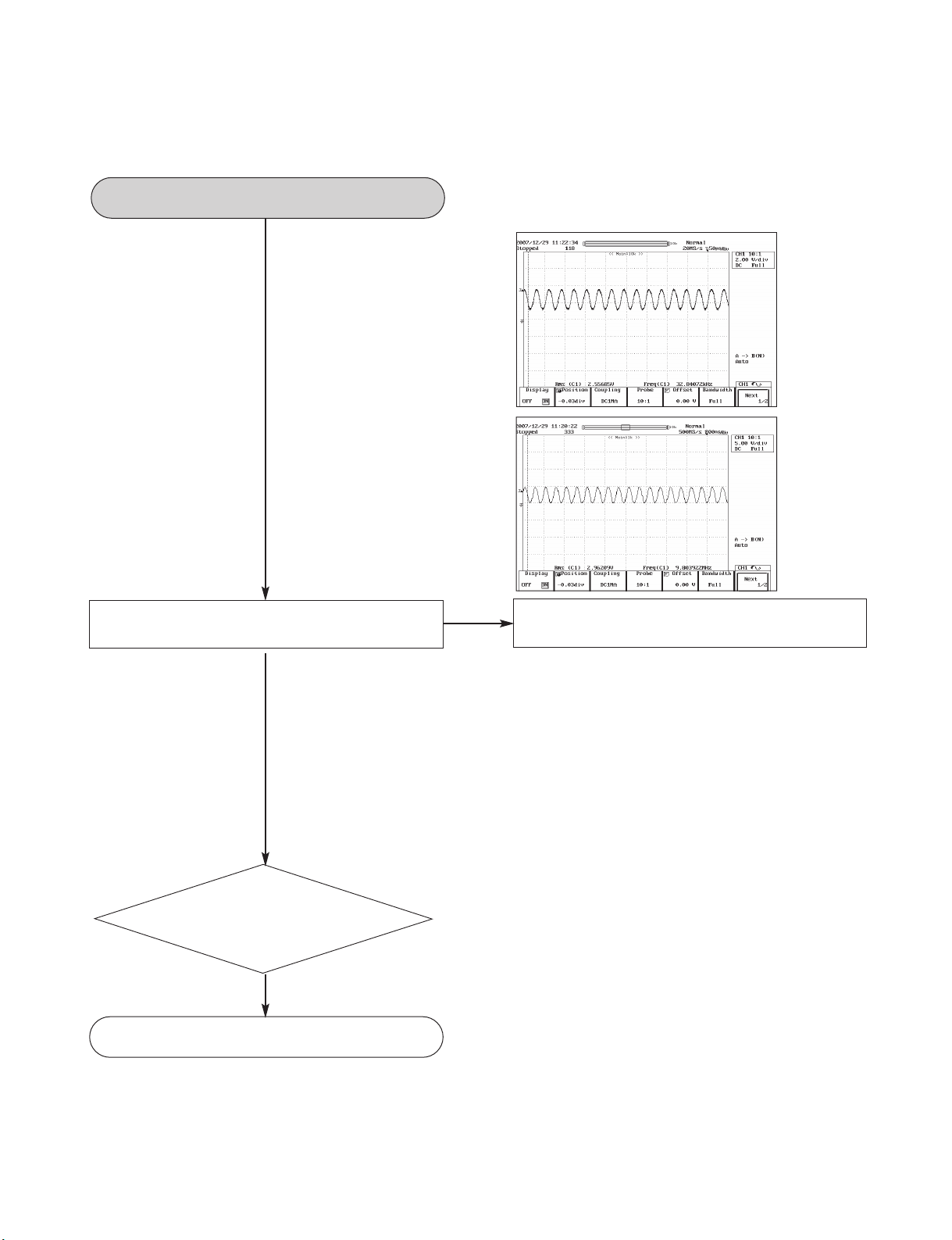
4. FLD DISPLAY PART CHECK
NO
YES
YES
YES
YES
Refer to SMPS
Troubleshooting
NO
Replace the related part
Check CN710
assembly
Check
10 PIN → - 27V
11 PIN→ 20V
12 PIN→ 25V
YES
FLT turned on
Check the power of CN710
10 11 12 PIN
YES
Check the
connecting condition
and the power of P3702
40PIN: FL- 20
39PIN: FL+ 25
38PIN: VKK-28vor higher
39PIN: 5.6V
YES
Check
IC304 PT6324
power 50 PIN VKK:-28V
9.52 PIN +5V
YES
YES
Check each pin
Check IC100 →
IC301 DATA communication
PIN PIN
27 PIN → 3PIN STB
26 PIN → 2PIN D
28 PIN → PIN CLK
OK
OK
OK
NO
Replace the related part.
NO
Replace the related part.
NO
NO
NO
If 5V is failed, check the input and
output power of D319 1SR35
IC100 IC303
27 PIN → 3PIN STB
28 PIN → 1PIN CLK
Check Data output
Check the data at both terminals
of LINE R330,331,332
YES
YES
YES
Check the related part
YES
Check the related part
OK
YES
FLD DISPLAY CHECK
 Loading...