

LG MASTER-K10S1 User Manual
User’s Manual
LG Programmable Logic Controller
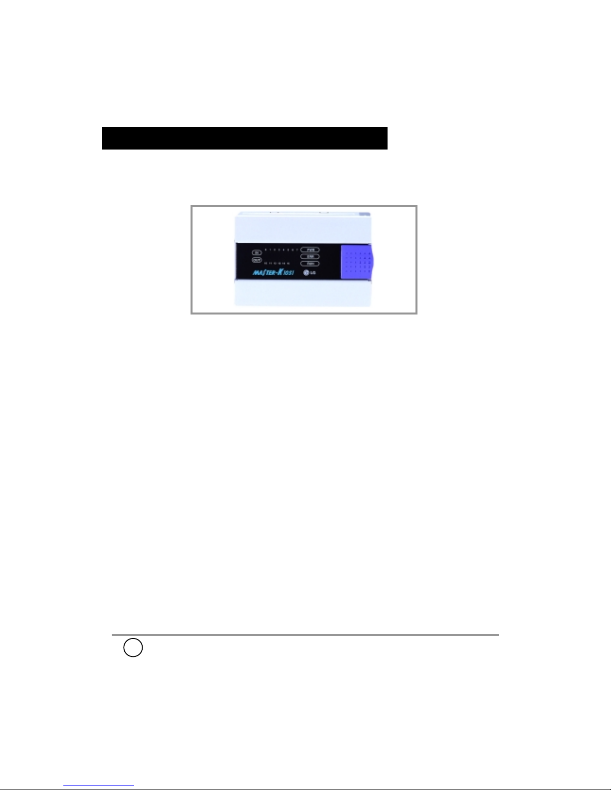
MASTER-K10S1
LG Industrial Systems Co., Ltd.
702004000
Warranty
• LGIS provides an 18 months warranty from the date of production.
• For troubles within the warranty period, LGIS will replace the entire
PLC or repair the troubled parts free of charge except the following
cases;
① the troubles caused by improper treatment or operation.
② the troubles caused by external devices.
③ the troubles caused by remodeling or repairing based on user’s
own discretion.
④ the troubles caused by natural disaster.
• This warranty is limited to the PLC itself only. It is not valid for the
whole system which the PLC is attached.
Installation Environment
1. Please avoid installing the PLC at following locations where;
2. Please install the PLC at least 50㎜ away from a duct or other devices.
3. Be sure to install the PLC in the cabinet which comply with IP54 or higher.
4. Be sure to place the PLC in the manufacturer’s original packing
while shipping or storing.
• temperature may experience ambient drops or rising.
(It should stay within 0℃ to 55℃(32 ~ 131℉))
• condensation may occur due to abrupt temperature changes.
• vibration and shock are directly transmitted to the PLC.
• the PLC is exposed to the direct rays of the sun.
• the PLC is exposed to corrosive or inflammable gas.
• the PLC is exposed to conductive powder.

2
MASTER-K10S1
■■■■
Characteristics
• The user program is stored in a EEPROM, and no battery back-up is required.
• Data communication through RS232C and RS485 is available.
• K10S1 includes a high speed counter being applicable for a simple positioning system.
• K10S1 series are suitable for the control of small machinery having I/O points
less than 14 .
■■■■
Power Supplying to the PLC
• To prevent the PLC from an improper
operation caused by the external noise,
place a insulation transformer and/or a
noise filter as shown in the right figure.
• Always install AC power cable and
signal or data lines in separate ducts or
bunches.
PLC
power
Insulation Transformer
FG
noise
filter
AC power
• The fuse in the DC power supply may be blown when the DC power
is supplied in reverse polarity.
• Be careful to connect power source cable to the correct terminal.
Internal device of PLC may be damaged by the improper lead connections.
• Supplying power beyond rated voltage/frequency may damage internal devices.
• Grounding
PLC
Other
Device
PLC PLC
Other
Device
Other
Device
<BEST> <GOOD>
<POOR>
Caution
When you supply power to external DC24V devices from the power unit of
K10S1, be careful not to exceed the maximum capacity of power unit.
(№ of inputs simultaneously ON X 7mA)
+ (№ of outputs simultaneously ON X 8mA)
+ ( ∑current consumption of external DC24V devices)
Note) The maximum capacity
of power supply
K10S1 : 100mA
The maximum
capacity of power
supply
<
!
3
MASTER-K10S1
■■■■
Specifications
•
General Specifications
Power Supplies (47 ~ 63Hz) K10S1 : 100~240VAC(Free Voltage)
& Consumption 7.4W
Dropout Tolerance 1/2 Cycle
DC Supply Output 0.1A
Withstanding Voltage DC 500V 10M
Ω
Grounding Grounding resistance ≤ 100
Ω
Noise Immunity 2000V, 1μs (Noise Simulator)
Vibration KSC0903
Shock KSC0905
Operation Temperature 0 ~ 55℃( 32 ~ 131℉)
Storage Temperature -25 ~ 75℃( -13 ~ 158℉)
Humidity 5 ~ 95% RH (Non-condensing), RH-2
Atmosphere Free from corrosive gas
ESD Severity Level Level ESD-3
Altitude under 2000m
•
Function al Specifications
Program control method Cyclic execution of stored program
I/O Processing Method Updated after each scan
No. of instructions 30 Basic instructions & 154 application instructions
Execution time 3.2~7.6 μs / step
Program capacity 800 steps
Memory device type EEPROM (8kbyte)
Memory device range P : I/O relay / P000 ~ P007 (8points for input)
P010 ~ P015 (6points for output)
M : Auxiliary relay / M000 ~ M15F (256points)
K : Keep relay / K000 ~ K07F (128points)
L : Link relay / L000 ~ L07F (128points)
F : Special relay / F000 ~F15F (256points)
T : 100ms timer / T000 ~ T031 (32points)
10ms timer / T032 ~ T047 (16points)
C : Counter / C000 ~ C015 (16points)
D : Word(16bit) data register
D000 ~ D063 (64word)
S : Step controller / S00.00~S15.99(16X100steps)
Counter Up-counter, Down-counter, Up/down-counter
Ring Counter (preset range : 0 ~65535)
Timer On delay-timer, Off delay-timer, Integrating timer,
Monostable timer, Retriggerable timer
(preset range : 0 ~ 65535)
High speed counter 1point, 8kpps, DC24V, Duty : 20 ~ 80%
Other functions RS232C, RS485 communication
4
MASTER-K10S1
•
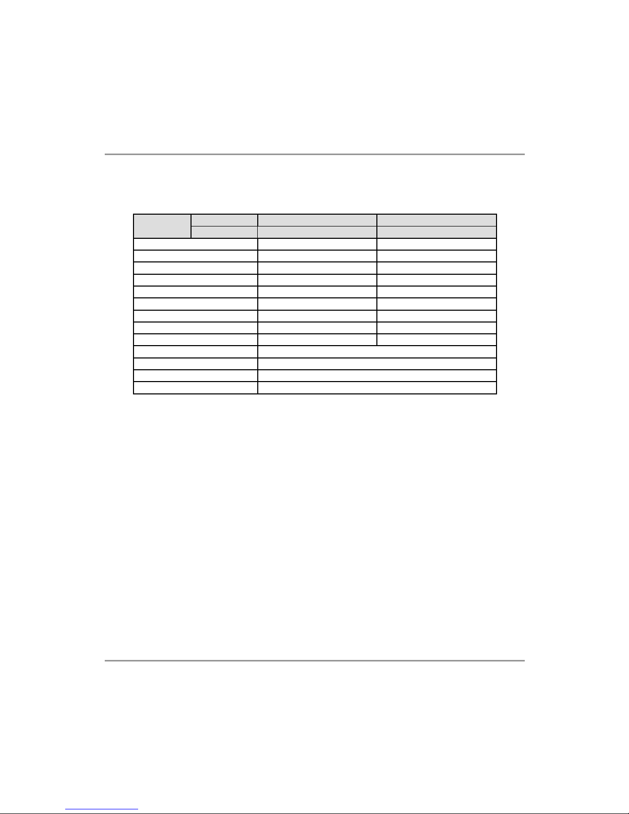
I/O Specification
K10S1
Note
)
• The expected life span of relay
The relay used in MASTER-K10S1 is FUJI’s RB1-E, and those manufacturer
guarantee 10million times (mechanical) and 0.1 ~ 3million times (electrical)
operation for their relays..
The durability of relay depends on the type of external load. Therefore, we highly
recommend customers to connect an external relay or SSR between PLC and
large inductive load for improved reliability and maintenance of PLC. The capacity
of external relay or SSR should be at least twice larger than the capacity of the
load.
• All outputs will be turned off when interruptions of CPU control, voltage drops /
interruptions, and/or power up/down occur.
• Improper terminal connection or overloads on I/O may cause a damage on the
internal devices.
Item
InputI/O
Rated Voltage
Type
Output
DC Relay
DC24V DC24V / AC110 ~ 220V
On : Operatin g Voltage
≥
DC19V
-
Off : Operating Voltage
≤
DC6V
-
Input Current
7± 2mA / point
-
Max. Outpu t Current - 1A / point, 3A / COM
On State Voltag e Drop -
≤
3V
Off State Leak ag e Current -
≤
0.1mA
Off → On Response Time
≤
5ms
≤
10ms
On → Off Response Time
≤
7ms
≤
10ms
I/O Status Indicator LED (Input : Green, Outp ut : Red)
Withstand Voltage AC1500V, 1 minute
Noise Immunity 2000Vpp, 1㎲ (Noise Simulator)
Insulation Device Photo Coupler
 Loading...