

LG Electronics M4716C User Manual

ENGLISH
OWNER’S MANUAL
MONITOR SIGNAGE
Please read this manual carefully before operating
your set and retain it for future reference.
MONITOR SIGNAGE MODELS
M4716C
www.lg.com

Table of Contents
Accessories 3
Connecting the Stand 4
Connecting the Speakers 5
Portrait Mode 6
Using the Remote Control 7
Part Names and Functions 9
Connecting to External Devices 10
Connecting to Your PC .......................................................................................................10
Using the LAN ......................................................................................................................12
Daisy Chaining Set ..............................................................................................................13
VESA FDMI Wall Mounting .................................................................................................14
Cable Management .............................................................................................................15
Video Input ...........................................................................................................................16
Component Input (480i/480p/576i/576p/720p/1080i/1080p) ..........................................17
HDMI Input (480p/576p/720p/1080i/1080p) ......................................................................18
User Menus 19
Screen Adjustment Options ..............................................................................................19
OSD Menu ............................................................................................................................21
Adjusting the OSD (On-Screen Display) .........................................................................22
Adjusting the Screen Automatically .................................................................................22
Adjusting Screen Color ......................................................................................................23
Adjusting Audio ...................................................................................................................29
Adjusting the Timer.............................................................................................................30
Selecting Options ...............................................................................................................31
Screen Tiling Options .........................................................................................................33
USB Options ........................................................................................................................35
Troubleshooting 49
Specifications 52
Controlling Multiple Set A1
2
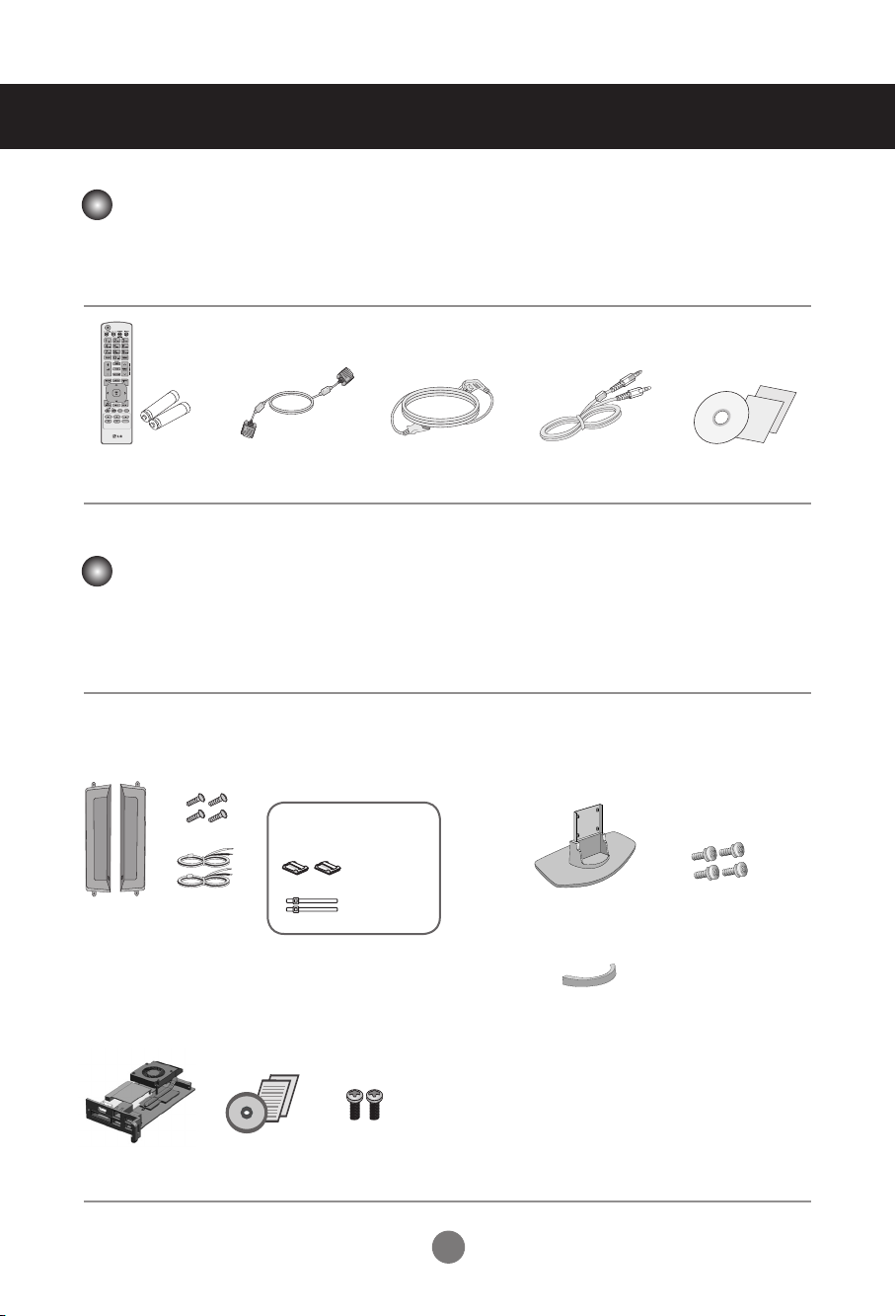
Accessories
Included Accessories
Thank you for your purchase. Check to make sure that the accessories shown immediately below have been
included with your set.
❖
Note that the accessories may look different from those shown here.
Remote Control
/ Batteries
D-Sub Signal
Cable
Power Cable Audio Cable (PC)
CD-ROM / Cards
Separately Purchased Accessories
Optional accessories are subject to change without prior notice to improve the performance of the set. New
optional accessories may be added periodically.
❖
Optional accessories (purchased separately) may vary depending on the model.
❖
Note that optional accessories may look different from those shown here.
Speaker Kit
❖
Applicable only for models that support the speakers.
Cable holder/Cable tie
They may not
be available
in some areas
or for some
Speaker(2)
Screws (4)
/ Cable (2)
models.
NC2000 Kit
❖
Applicable only for models that support the NC2000.
Stand Kit
❖
Applicable only for models that support stand.
Stand(1)
Cable management (1)
Screws (4)
NC2000 CD-ROM /
Cards
Screws (2)
3
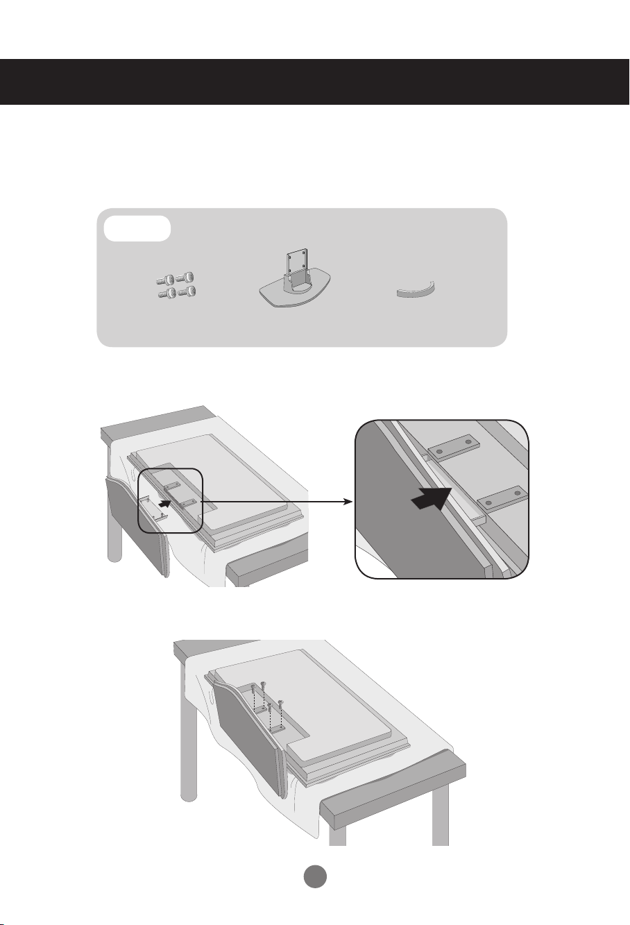
Connecting the Stand
- Only on some models.
Take the parts for the stand out of the box and assemble them as
1.
shown in the picture.
Parts
Place a soft cloth on a table and place the set screen side down upon the table.
2.
Connect the stand as shown below.
Use the screws to secure the stand on the rear side of the set as shown
3.
below.
First, check if the following parts are all present.
Screws (4)
Stand(1)
Cable management (1)
4
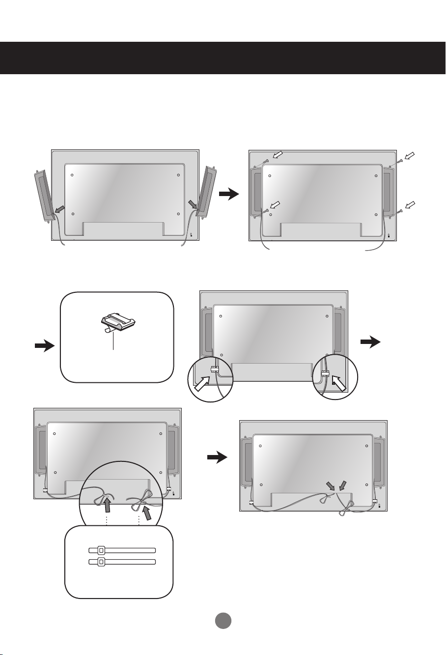
Connecting the Speakers
- Only on some models.
Attach the speakers to the set using screws as shown below. Then, connect the
speaker cable.
After installing your speakers, use holders and cable ties to organize the speaker
cables.
Cable holder
Remove the paper.
* This feature is not available on all models.
Cable ties
* This feature is not available on all models.
When the speakers are installed.
*Connect the input terminal with the
proper color match.
5
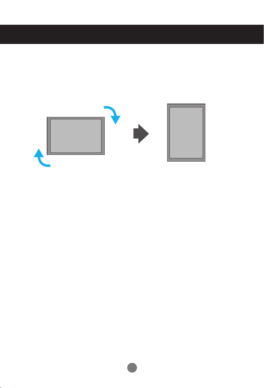
Portrait Mode
- Only on some models.
"When installing in portrait mode, rotate the set clockwise."
6
P
A
G
E
INPUT
ENERGY
SAVING
MARK
ARC
ON
OFF
. , !
ABCDFG
GHIJKLMNO
PQRSTUV
1/a/A
- * #
WXYZ
CLEAR
OK
S.MENU
MONITOR
PSM
AUTO
MUTE
BRIGHT
NESS
MENU
ID
BACK
TILE
ON
OFF
EXIT
1
2
3
4
5
6
7
8
9
10
11
Using the Remote Control
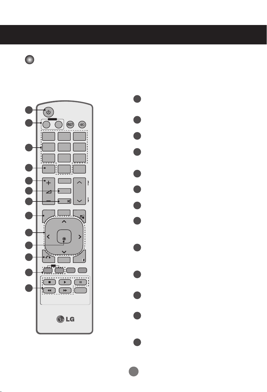
Remote Control Buttons
POWER On / Off Button
1
- Switches the set on from standby or off to
standby.
MONITOR On / Off Button
2
- Turns off the monitor and then turn it back on.
Number and Letter Buttons
3
- Type numbers and letters.
1/a/A Button
4
- Selects numbers and letters. (SuperSign
input only).
Volume Up/Down Button
5
- Adjusts the volume.
PSM Button
6
- Selects the Picture Status mode.
MUTE Button
7
- Switches the sound on or off.
MENU Button
8
- Selects a menu.
- Clears all on-screen displays and returns to
monitor viewing from any menu.
Up/Down/Left/Right Buttons
9
- Allows you to navigate the on-screen menus
an d adj ust t he s yste m se ttin gs t o you r
preference.
12
OK Button
10
- Acc epts your se lec ti on or disp lays the
current mode.
13
BACK Button
11
- Allows the user to move return one step in an
interactive application.
ID ON/OFF Button
12
- When the number of input ID is equal to the
number of ID Mode, you can control the monitor
which you want in the multi display condition.
USB Menu Control Buttons
13
- Adjusts the USB menu (Photo List, Music
List and Movie List).
7
Using the Remote Control
P
A
G
E
INPUT
ENERGY
SAVING
MARK
ARC
ON
OFF
. , !
ABCDFG
GHIJKLMNO
PQRSTUV
1/a/A
- * #
WXYZ
CLEAR
OK
S.MENU
MONITOR
PSM
AUTO
MUTE
BRIGHT
NESS
MENU
ID
BACK
TILE
ON
OFF
EXIT
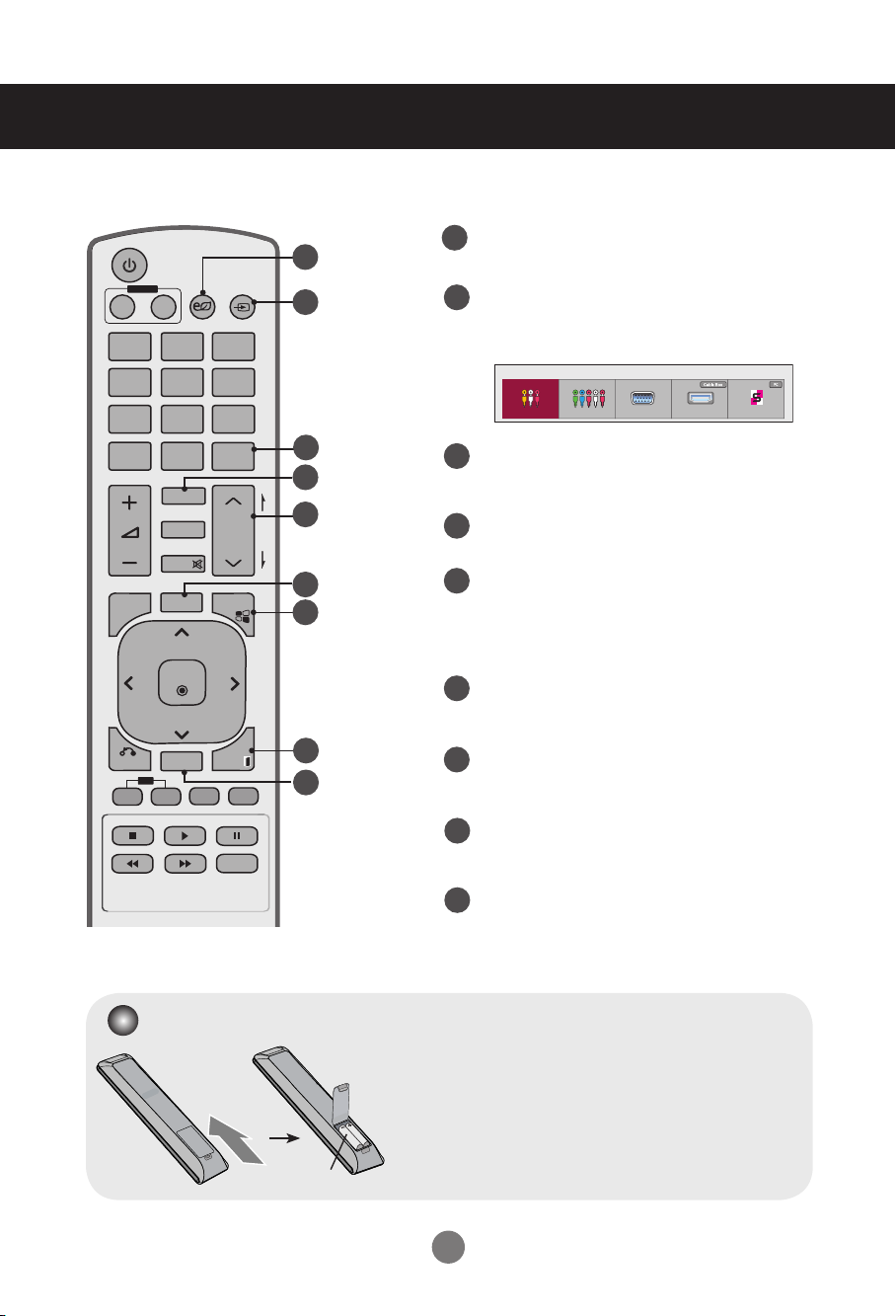
ENERGY SAVING Button
14
15
14
- Adjusts the Energy Saving mode of the set.
INPUT Select Button
15
Accesses the Input Signal Window.
Selects the signal type you want using ◄ ►.
Input List
AV Component RGB HDMI/DVI SuperSign
16
17
18
CLEAR Button
16
- Deletes the numbers and letters you typed
(SuperSign input only).
ARC Button
17
- Selects the Aspect Ratio mode.
BRIGHTNESS Button
19
20
18
- Adjusts the resolution and bright ne ss by
pressing Up and Down.
- In USB mode, the OSD menu has the Page
function to move to the next file list.
AUTO Button
19
- Automatically adjusts picture position and
minimizes image instability (RGB input only).
21
22
S.MENU Button (SuperSign Menu Key)
20
- Selects the SuperSign OSD Menu
(SuperSign input only).
EXIT Button
21
- Clears all on-screen displays and returns to set
normal viewing from any menu.
TILE Button
22
- Selects the TILE mode.
Inserting Batteries into the Remote Control
1. Slide off the battery cover.
2. Insert the batteries with correct polarity ( + / - ).
3. Close the battery cover.
4. To remove the batteries, perform the installation actions
AAA Type
in reverse.
• Dispose of used batteries accordance with local
regulations to prevent environmental pollution.
8
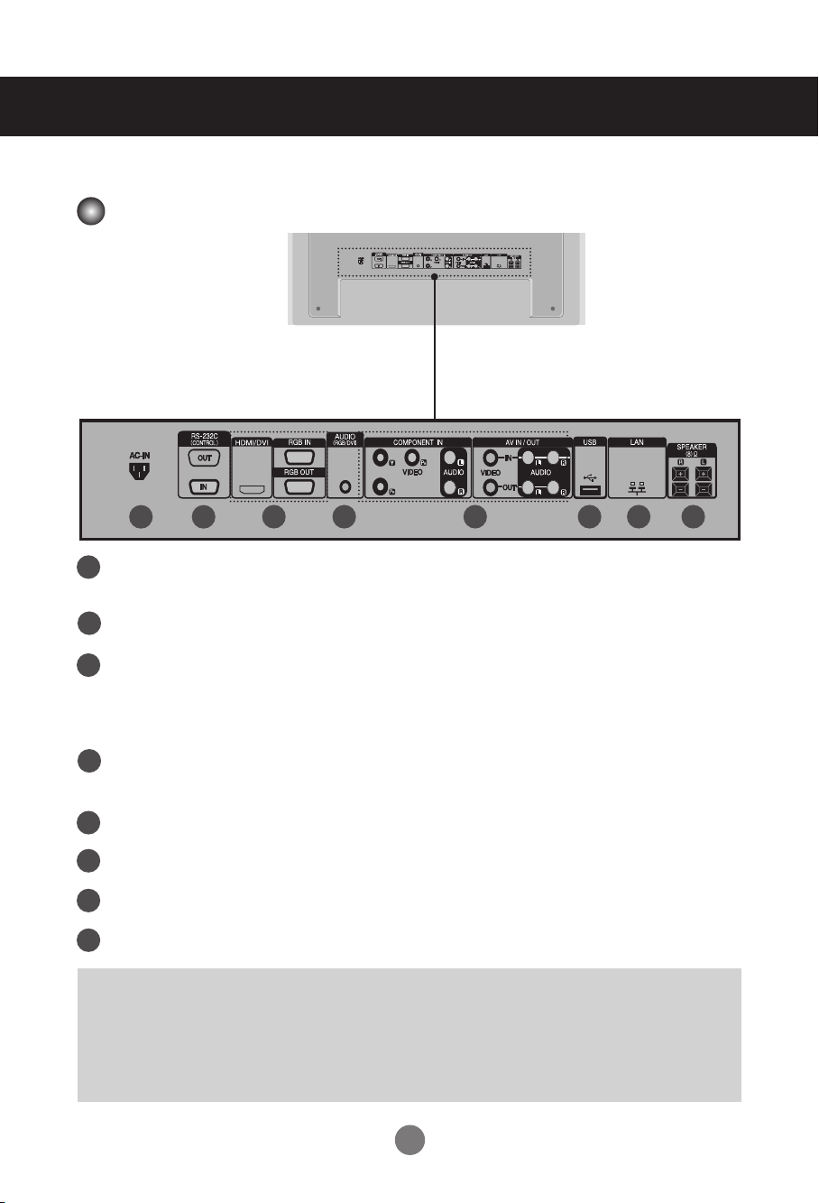
Part Names and Functions
* The set image in the user's guide may be different from the actual image.
Rear View
1 2
Power Connector
1
Connect the power cord.
RS-232C Serial Ports
2
RGB, HDMI/DVI Ports
3
HDMI supports high definition input and HDCP (High-bandwidth Digital
Content Protection). Some devices require HDCP in order to display HD
signals.
PC Sound Jack
4
Connect the audio cable to the LINE OUT* jack of the PC sound card.
AV Ports
5
USB Port
6
LAN Port
7
Speaker Ports
8
* LINE OUT
A terminal that is used to connect to the speaker including a built-in amplifier (amp).
Check the connecting terminal of the PC sound card before connecting. If the Audio Out of the PC
sound card only has a Speaker Out jack, reduce the PC volume. If the Audio Out of the PC sound card
supports both Speaker Out and Line Out, convert to Line Out using the card jumper of the program
(refer to your sound card's manual).
43 65 87
9
Connecting to External Devices
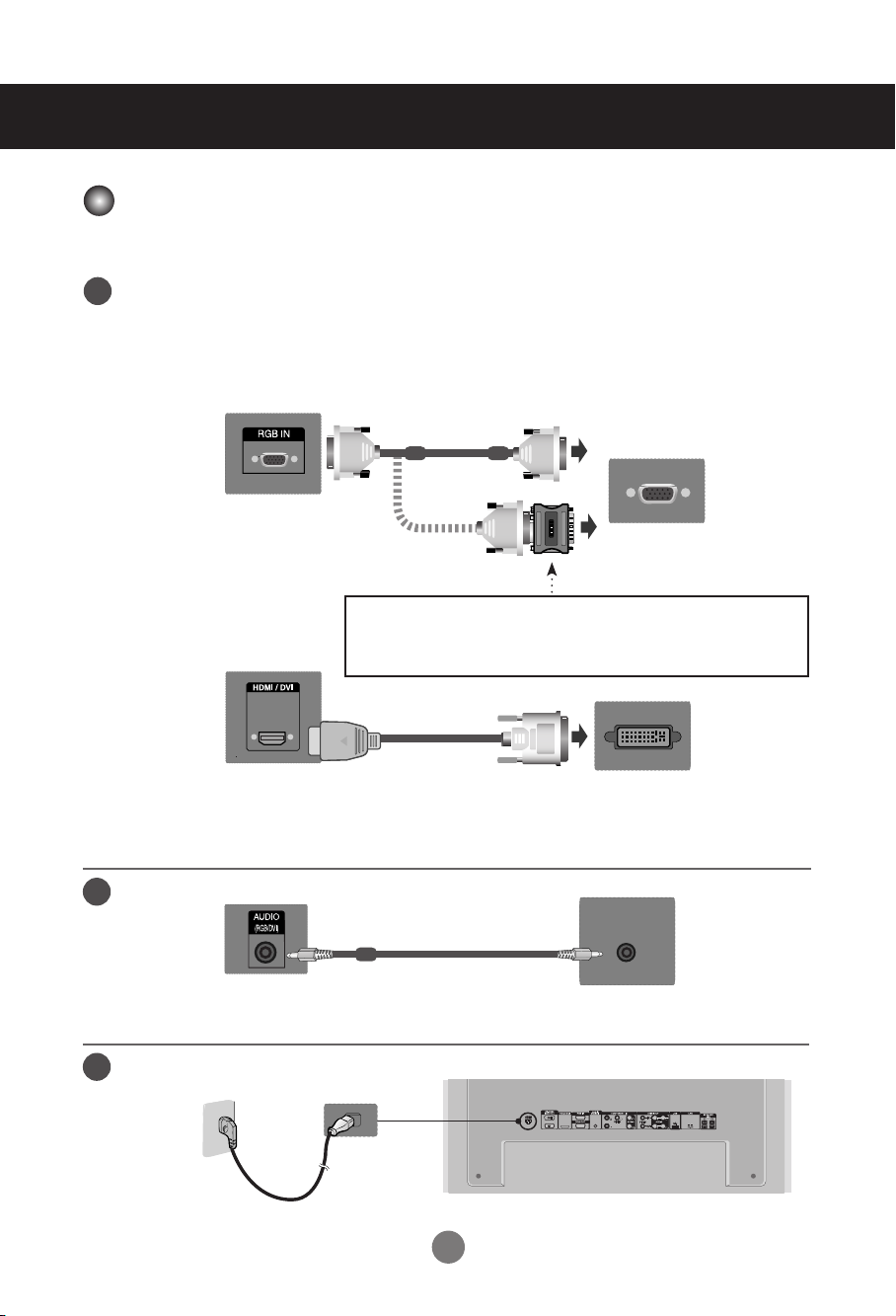
Connecting to Your PC
Check that the computer, monitor and the peripherals are turned off. Then, connect the
1
signal input cable.
Connecting with a D-Sub Signal Input Cable.
A.
Connecting with an HDMI-DVI Signal Input Cable (not included)
B.
* When HDMI PC is used, a compatibility problem may occur.
A.
PC
Rear back of the set.
MAC
Macintosh Adapter (not included)
Use the standard Macintosh adapter since an incompatible adapter
that uses a different signaling system is available on the market.
B.
PC/MAC
(not included)
Rear back of the set.
* Use shielded signal interface cables (D-sub 15 pin cable, DVI cable) with ferrite cores to
maintain standard compliance with your set.
Connect the Audio cable.
2
Rear back of the set.
Connect the power cord.
3
Rear back of the set.
10
PC
PC
Connecting to External Devices
4
5
Press Power.
1.
Turn on the PC.
2.
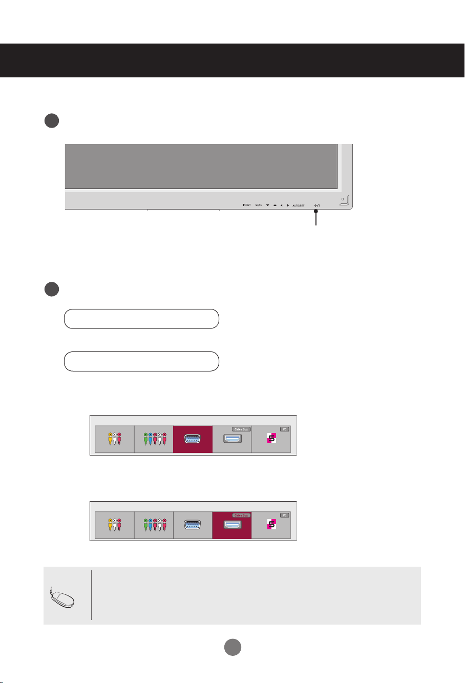
Select an input signal.
Press INPUT on the remote control to select the input signal.
INPUT → ◄ ► → OK
Or, press INPUT on the bottom of the set.
INPUT →◄ ► → AUTO/SET
A.
Connecting with a D-Sub Signal Input Cable.
• Select RGB: 15-pin D-Sub analog signal.
Power button
Input List
AV Component RGB HDMI/DVI SuperSign
Connecting with an HDMI to DVI Signal Input Cable.
B.
• Select HDMI/DVI: DVI Digital signal or HDMI Digital signal.
Input List
AV Component RGB HDMI/DVI SuperSign
Note
• Connecting two computers.
Connect the signal cables (HDMI-DVI and D-Sub) to each computer.
Press INPUT on the remote control to select the computer to use.
• Connect to a grounded power outlet directly on the wall or on a grounded power strip.
11
Connecting to External Devices
Network
Using the LAN
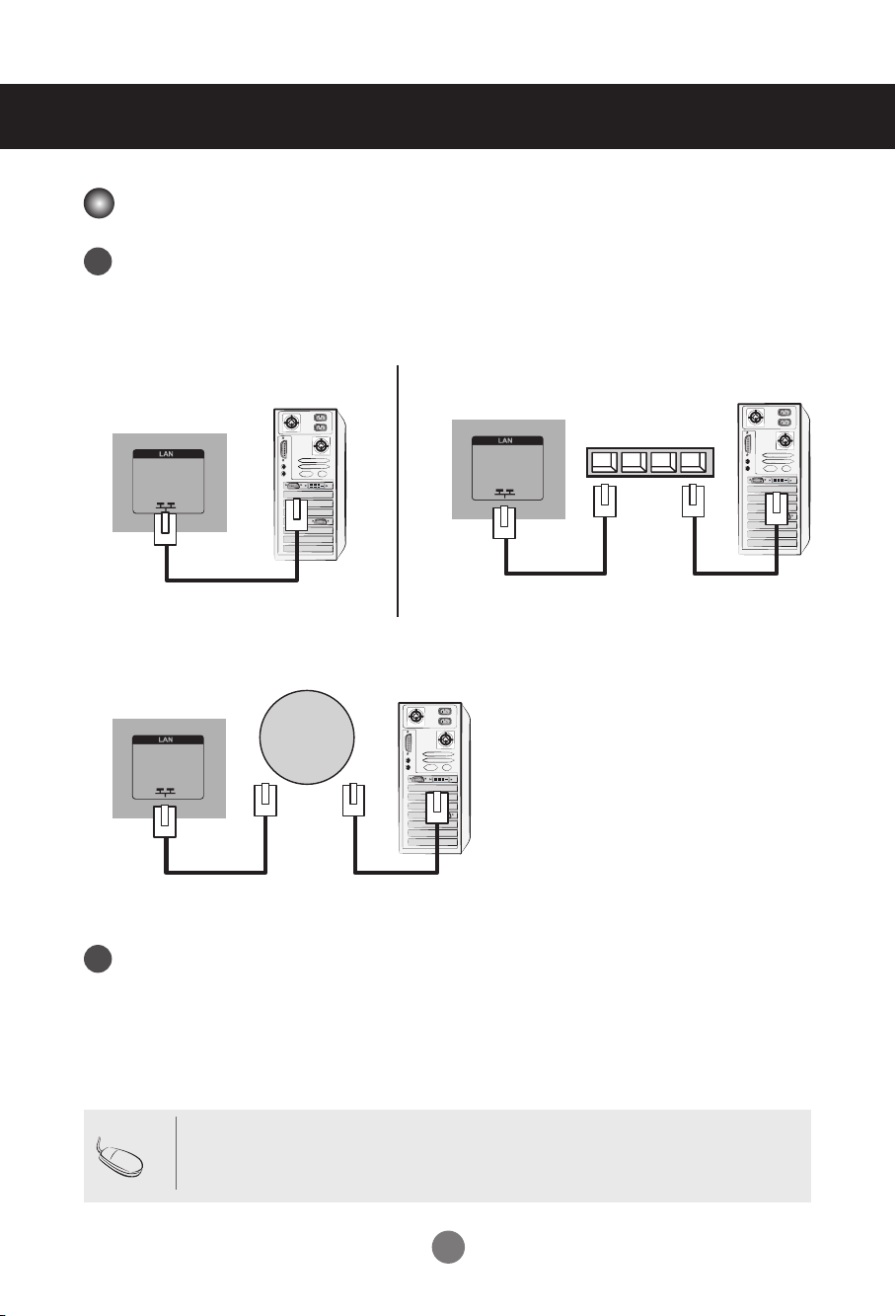
Connect the LAN cable as shown below.
1
Connect PC to Monitor.
LAN
Set
Using the Internet.
C.
LAN
Set
PC
PC
Using a Router (Switch).
B.A.
LAN
Set
Switch
PC
Connect the LAN cable and install the eZ-Net Manager program on the CD-ROM.
2
For more information about the program, please refer to the eZ-Net Guide on the included
CD-ROM.
Note
• Using a LAN establishes communication between your PC and the set and enables
use of the OSD menus on the PC as well as the set.
12
Connecting to External Devices
Daisy Chaining Set
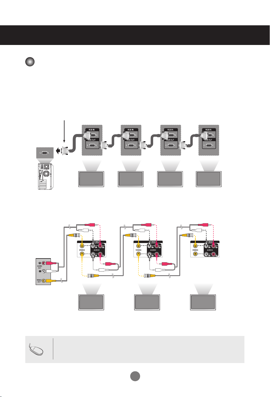
Using RGB Input
A.
To use different set connected to each other, connect one end of the signal input cable
(15-pin D-Sub signal cable) to the RGB OUT connector of set 1 and connect the other
end to the RGB IN connector of other set.
15-pin D-Sub Signal Cable
PC
PC
Using AV Input
B.
Set 1
Set 2
Set 3
Set 4
Audio Cable
(not included)
Video
BNC Cable
(not included)
Note
• The number of set that can be connected to one output may vary depending on signal
Set 1
status and cable loss. If the signal status is good, and there is no cable loss, it is possible to connect up to 9 set. If you want to connect more than nine, a distributor is
recommended.
13
Set 2
Set 3
Connecting to External Devices
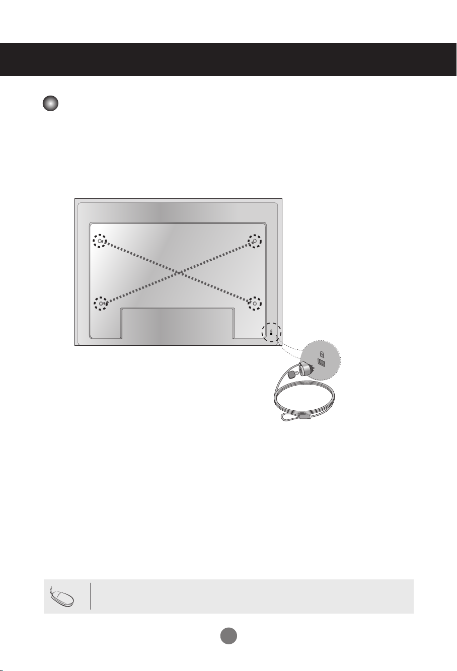
VESA FDMI Wall Mounting
This set supports a VESA FDMI compliant mounting interface. These mounts are
purchased separately and are not available from LG. Refer to the instructions
included with your wall mount for more info.
Note
Kensington Security Slot
The set is equipped with a Kensington
Security System connector on the back
panel. The cable and lock are available
separately and are not sold by LG. For
more info, visit http://www.kensington.
com.
• There is a switch on the lower side of the back. You can set the switch to "On"
before connecting a power cord to make it more convenient.
14
Connecting to External Devices
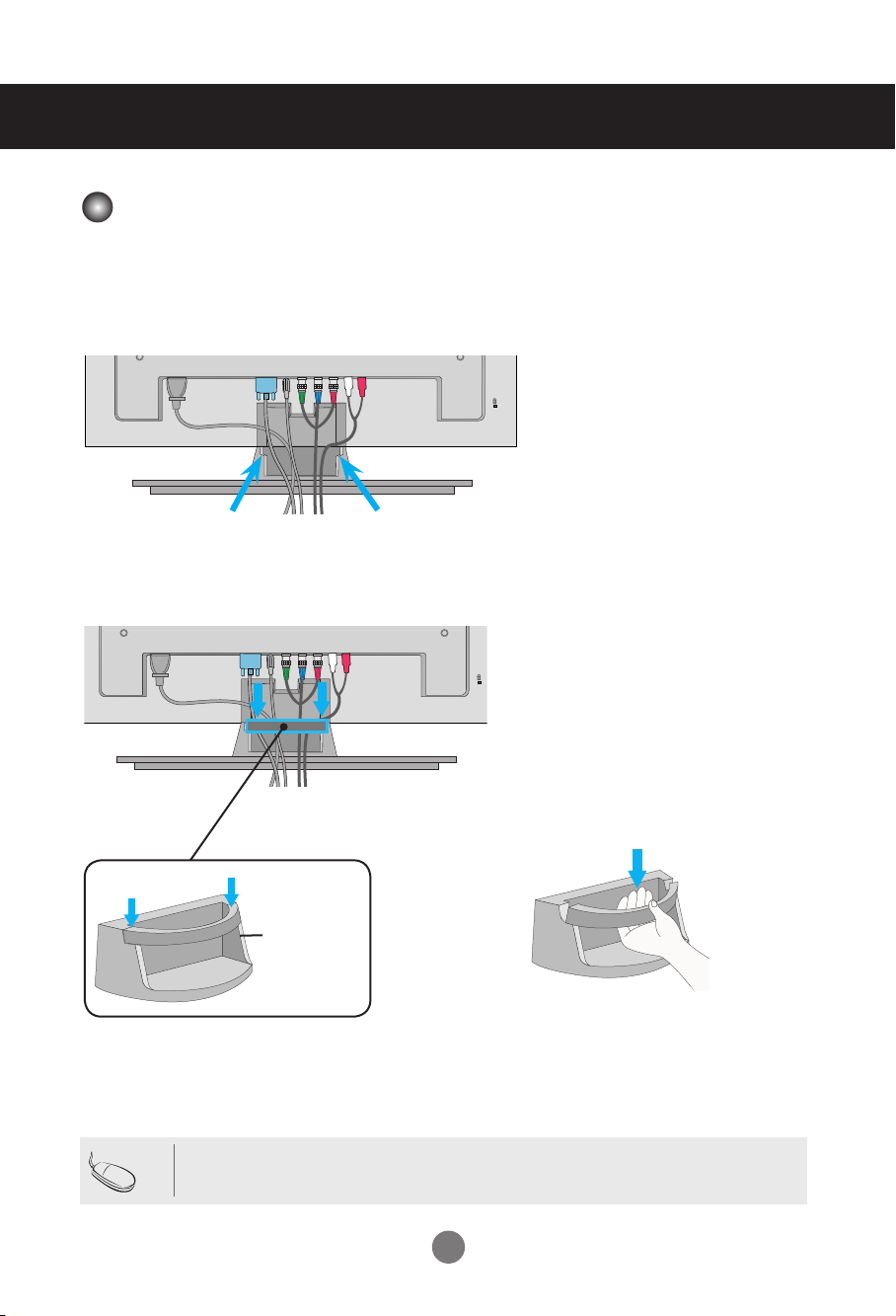
Cable Management
- Only on some models.
Arrange the cables in the center as shown in the following picture.
1.
2.
Fit the cable guide to the back to help manage the cables.
Note
Removing the cable guide.
Cable
Management
Hold the Cable management with both hands
and pull it downward.
•
Do not use the cable management as a handle for the Monitor.
15
Connecting to External Devices
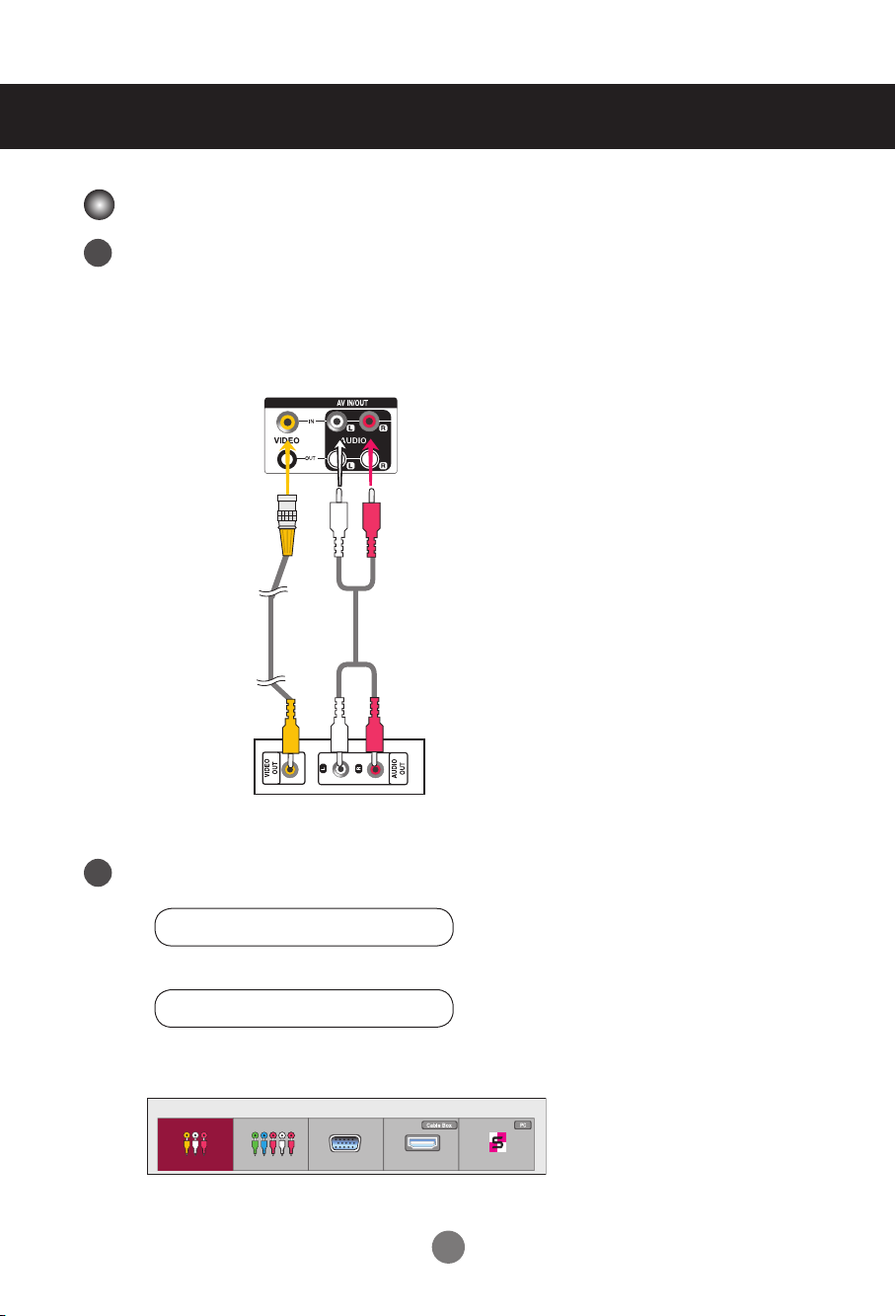
Video Input
Connect the video cable as shown below and then connect the power cord
1
(see page 10).
Connecting with a BNC Cable
• Connect the input terminal with a proper color match.
Set
BNC Cable
(not included)
VCR/DVD Receiver
Select an input signal.
2
Press INPUT on the remote control to select the input signal.
Audio Cable
(not included)
INPUT → ◄ ► → OK
Or, press INPUT on the bottom of the set.
INPUT →◄ ► → AUTO/SET
Connecting with a BNC Cable
• Select AV.
Input List
AV Component RGB HDMI/DVI SuperSign
16
Connecting to External Devices
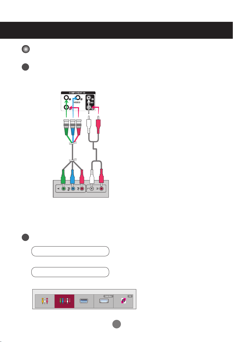
Component Input (480i/480p/576i/576p/720p/1080i/1080p)
Connect the AV cable as shown in the below figure, then connect the power cord (see page 10).
1
• Connect the input terminal with the matching color.
Set
BNC Cable
(not included)
HDTV Receiver
Note:
- Some devices may require HDCP in order to display HD signals.
- Component doesn't support HDCP.
Select an input signal.
2
Press INPUT on the remote control to select the input signal.
Audio Cable
(not included)
INPUT → ◄ ► → OK
Or, press INPUT on the bottom of the set.
INPUT →◄ ► → AUTO/SET
• Select Component.
Input List
AV Component RGB HDMI/DVI SuperSign
17
Connecting to External Devices
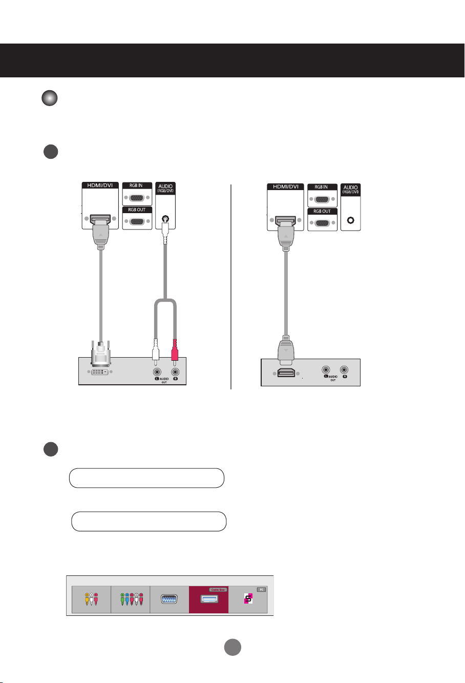
HDMI Input (480p/576p/720p/1080i/1080p)
HDMI supports high definition input and HDCP (High-bandwidth Digital Content
Protection). Some devices require HDCP in order to display HD signals.
Connect the AV cable as shown below and connect the power cord (see page 10).
1
Set
HDMI-DVI
Signal Cable
(not included)
VCR/DVD/Set-top Box
Note: Dolby Digital is not supported.
Select an input signal.
2
Press INPUT on the remote control to select the input signal.
RCA-PC
Audio Cable
(not included)
Set
HDMI Signal Cable
(not included)
VCR/DVD/Set-top Box
INPUT → ◄ ► → OK
Or, press INPUT on the bottom of the set.
INPUT →◄ ► → AUTO/SET
Connecting with an HDMI-DVI Signal Input Cable or an HDMI Signal Input Cable.
• Select HDMI/DVI.
Input List
AV Component RGB HDMI/DVI SuperSign
18
User Menus
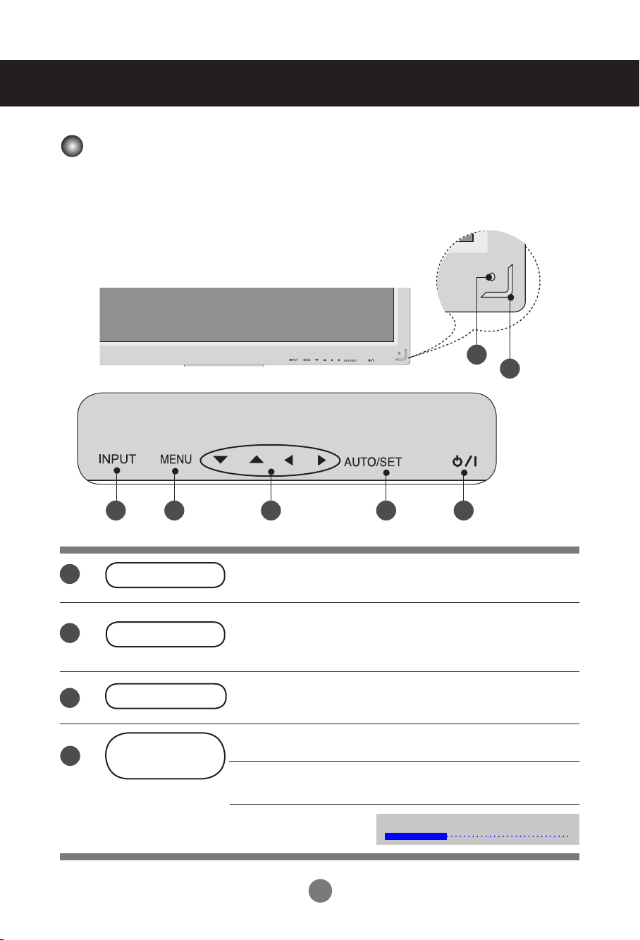
Screen Adjustment Options
7
2
6 3 4 5 1
1
2
3
4
Power Button
Power Indicator
MENU Button
OSD Select /
Adjust Button
Turns the set on/off.
This Indicator lights up green when the set is operating
normally (on mode). If the set is in sleep mode (Energy
Saving), the indicator color changes to amber.
Shows/hides the OSD (On-Screen Display) menu.
Selects an icon or adjusts the setting in the OSD menu.
▲ ▼ Adjusts up and down.
◄ ► Adjusts the volume.
19
Volume
35
User Menus
Screen Adjustment Options
5
6
7
AUTO/SET Button
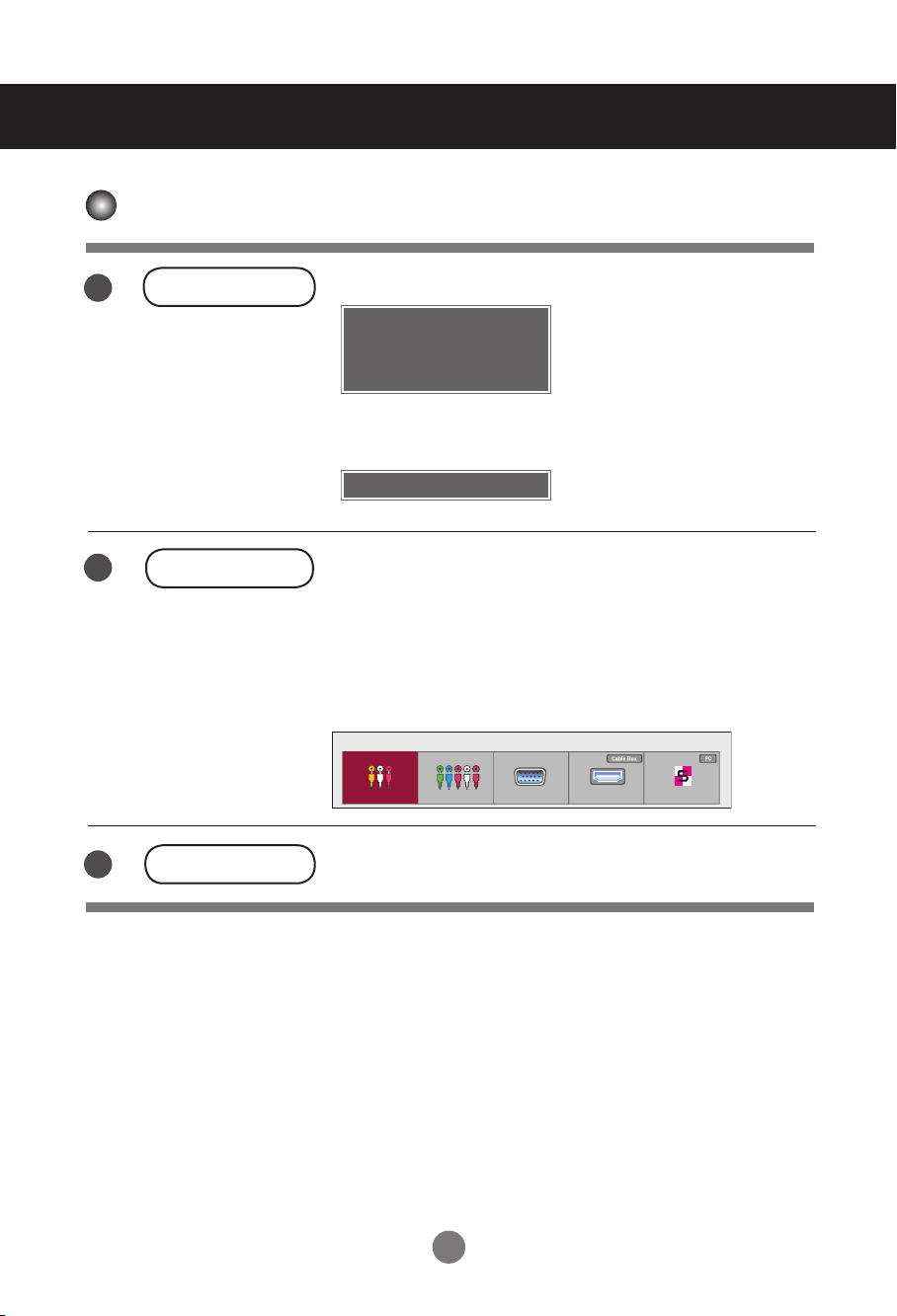
INPUT Button
IR Receiver
[For PC Analog signal]
Auto in progress
For optimal display change
resolution to 1920 x 1080
[When XGA Mode is active and
1920 x 1080 is selected]
Auto in progress
INPUT → ◄ ► → AUTO/SET
- Toggles between inputs
AV Composite Video
Component HDTV, DVD
RGB 15-pin D-Sub analog signal
HDMI/DVI Digital signal
SuperSign SupeSign
Input List
AV Component RGB HDMI/DVI SuperSign
The sensor from which the set receives signals from the
remote control.
20
User Menus
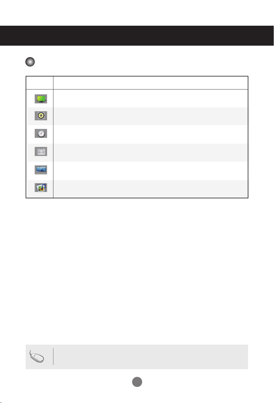
OSD Menu
Icon Function Description
Adjusts screen brightness, contrast and color to your preference.
Picture
Audio
Time
Option
Tile
USB
Adjusts the audio.
Adjusts the timer.
Adjusts the screen status according to conditions.
Adjusts tile options.
Adjusts USB options.
Note
OSD (On-Screen Display)
• The OSD function enables you to adjust the screen status conveniently since it
provides graphical menu representation.
21
User Menus
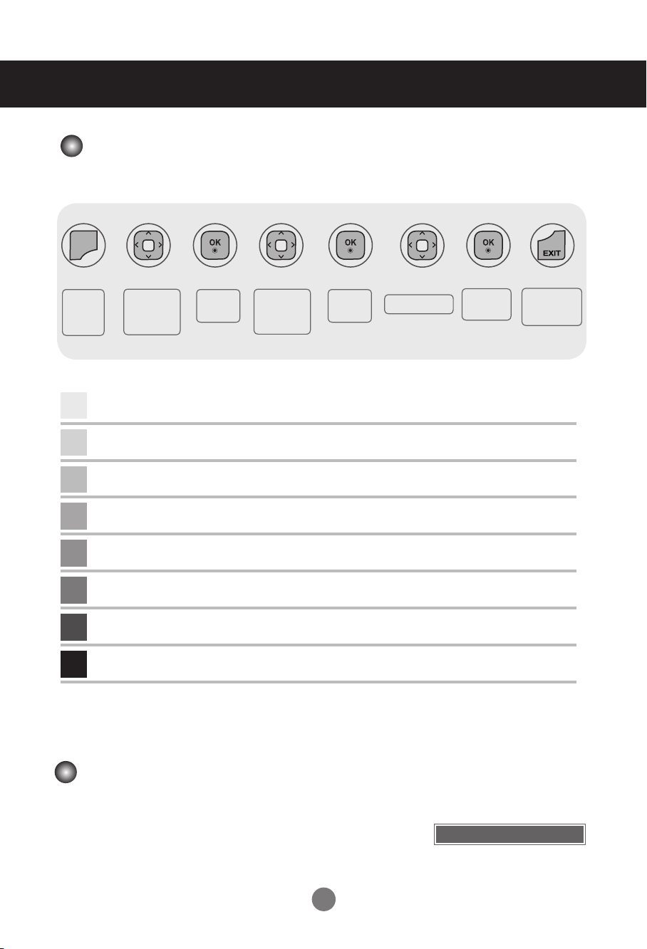
Adjusting the OSD (On-Screen Display)
MENU
➩ ➩ ➩ ➩
➩ ➩ ➩
Pops up
the menu
screen
1
2
3
4
5
6
7
8
Move where
you want to
adjust
Press MENU to bring up the OSD.
To access a control, use ▲▼.
When the icon you want becomes highlighted, press OK.
To access a control, use ▲▼.
When the list you want becomes highlighted, press OK.
Use ▲▼◄ ► to adjust the item to the desired level.
Accept the changes by pressing OK.
Exit the OSD by pressing EXIT.
Select a
menu icon
Move where
you want to
adjust
Select a
menu list
Adjust the status
•
Use the remote control to adjust the OSD.
Save
adjustment
Exit from the
menu screen.
Adjusting the Screen Automatically
Press AUTO/SET (AUTO on the remote Control) when viewing a
PC analog signal. The optimal screen settings will be selected
that suit the current mode. If adjustments are not satisfactory,
adjust the screen manually.
22
[When XGA Mode is active and
1920 x 1080 is selected]
Auto in progress
User Menus
H - 80
AV
HDMI / DVI
RGB
SuperSign
Component
ARC
MODE
16 : 9
Just Scan
Original
4 : 3
1 : 1
14 : 9
Zoom
Cinema Zoom 1
Full Wide
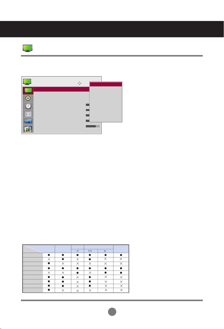
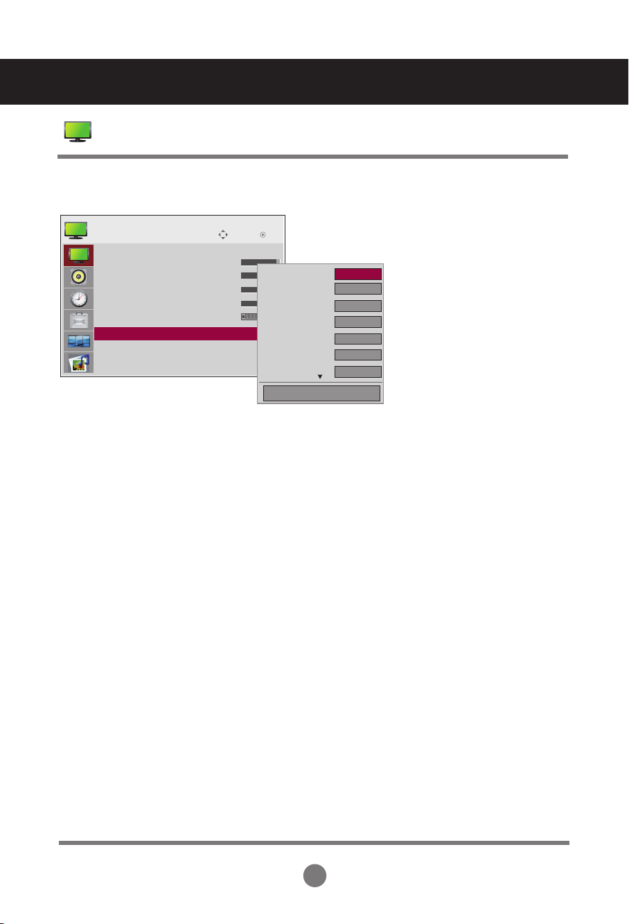
Adjusting Screen Color
Aspect Ratio
Move
PICTURE
Aspect Ratio : 16:9
Aspect Ratio : 16:9
ꕊ Energy Saving : Off
Picture Mode : Standard
• Backlight 70
• Contrast 90
• Brightness 50
• Sharpness 70
• Color 60
ꔋ
▼
To select the image size of the screen.
16:9:
Widescreen mode.
Just Scan:
Displays the full signal data without cropping any of the image.
(*This menu is activated only in 720p,1080p,1080i (HDMI/DVI-DTV, Component mode)
Original:
The aspect ratio is not adjusted from the original signal and is set by the program being
watched.
4:3:
Selects a 4:3 aspect ratio image.
1:1: The aspect ratio is not adjusted from the original. Used in PC mode (only HDMI/ DVI PC, RGB PC).
14:9:
14:9 programs are viewed normally in 14:9 with black bars added to the top and bottom.
4:3 programs are magnified on the top/bottom and left/right sides.
Zoom:
4:3 programs are magnified until they fill the 16:9 screen. The top and bottom will be cut off.
Cinena Zoom 1:
Choose Cinema Zoom when you wish the picture to be altered, both horizontally
extended and vertically cropped. This is a good compromise between signal
alteration and screen coverage.
Full Wide:
When the set receives a wide screen signal, it causes you to adjust the picture
horizontally or vertically, in linear proportion, to fill the entire screen.
OK
16:9 ꔋ
16:9
Just scan
Original
4:3
14:9
Zoom
Cinena Zoom 1
Full Wide
23
User Menus
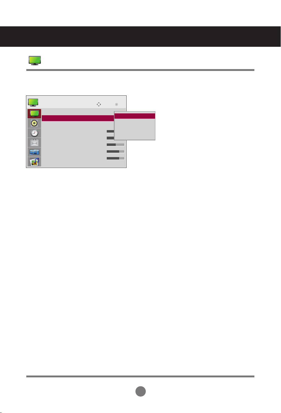
Adjusting Screen Color
Energy Saving
Move
PICTURE
Aspect Ratio : 16:9
ꕫ Energy Saving : Off
ꕊ Energy Saving : Off ꔋ
Picture Mode : Standard
• Backlight 70
• Contrast 90
• Brightness 50
• Sharpness 70
• Color 60
▼
The screen brightness adjusting menu helps you save energy.
Level: 4 screen brightness levels are available.
- Off: 100% light
- Level 1: 80% light
- Level 2: 60% light
- Level 3: 40% light
OK
Off ꔋ
Off
Level 1
Level 2
Level 3
24
User Menus
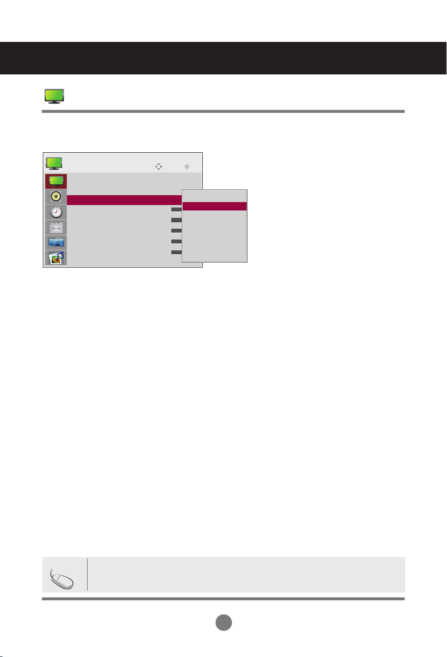
Adjusting Screen Color
Picture Mode
Move
PICTURE
Aspect Ratio : 16:9
ꕊ Energy Saving : Off
Picture Mode : Standard
Picture Mode : Standard
• Backlight 70
• Contrast 90
• Brightness 50
• Sharpness 70
• Color 60
▼
ꔋ
The picture mode menu toggles between screen presets.
Standard: This is the optimum viewing condition for general users.
Vivid: Displays a sharp image.
Cinema: This mode optimizes video for watching movies.
Sport: This mode emphasizes dynamic video and primary colors (e.g. white, uniforms,
grass, sky blue, etc.) by realizing the optimal image settings for sports.
Game: This is the mode for fast response speeds for video games.
Expert1,2 : Select this option to use the user-defined settings.
OK
Vivid
Standard ꔋ
Standard
Cinema
Sport
Game
Expert 1
Expert 2
Note
• If the 'Picture Mode' setting in the Picture menu is set to Vivid, Standard, Cinema,
Sport or Game, the subsequent menus will be automatically set.
25
User Menus
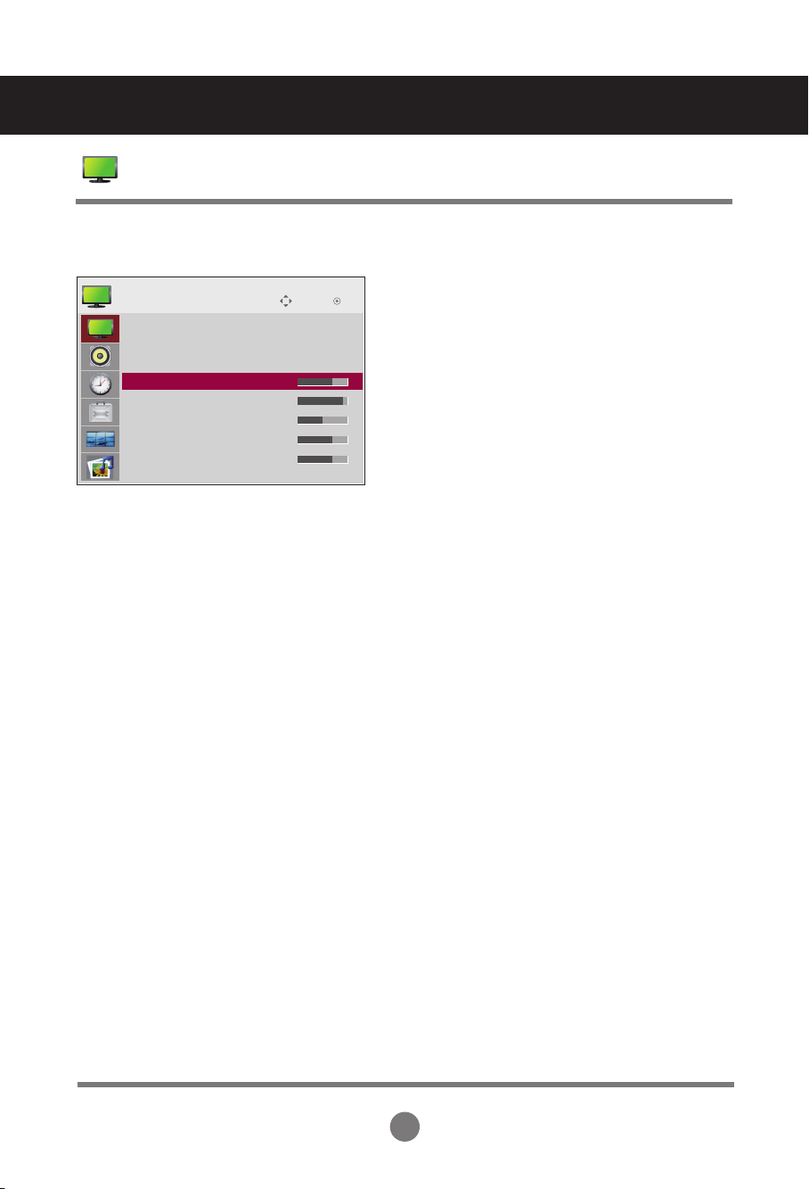
Adjusting Screen Color
Picture Mode
Move
OK
ꔋ
PICTURE
Aspect Ratio : 16:9
ꕊ Energy Saving : Off
Picture Mode : Standard (User)
• Backlight 70
• Backlight 70
• Contrast 90
• Brightness 50
• Sharpness 70
• Color 60
▼
Backlight: Adjusts the brightness of LCD panel.
Contrast: Adjusts the difference between light and dark levels.
Brightness: Adjusts the brightness of the screen.
Sharpness: Adjusts the clearness of the screen (function works in DTV mode).
Color: Adjusts the color (works in DTV mode).
Tint: Adjusts the tint (function works in DTV mode).
26
User Menus
Adjusting Screen Color
Advanced Control
Move
PICTURE
▲
• Contrast 90
• Brightness 50
• Sharpness 70
• Color 60
• Tint 0
• Advanced Control
• Advanced Control ꔋ
• Picture Reset
Screen
Color Temperature: Color Settings
Cool: Slightly purple temperature.
Medium: Slightly blue temperature.
Warm: Slightly red temperature.
Dynamic Contrast: Optimizes the contrast automatically according to the brightness of the
reflection.
Dynamic Color: Adjusts the color of the reflection automatically to reproduce natural colors
as closely as possible.
Noise Reduction: Removes noise up to the point where it does not damage the original
picture.
Gamma: Sets your own gamma value.
On the set, high gamma values display whitish images and low gamma
values display high contrast images.
Black Level: Adjusts the contrast and the brightness using the black level of the screen
(function works in the following modes: AV, Component, HDMI-DTV).
Low: The reflection of the screen gets darker.
High: The reflection of the screen gets brighter.
Film Mode: When you watch a movie, this function adjusts the set to the best picture
appearance (function works in the following modes: AV, Component
480i/576i/1080i, HDMI/DTV 480i/576i/1080i).
White Balance: Adjusts the overall color of the screen to your preferences (function works
in the following modes - Expert 1, Expert 2 Picture mode).
Color Management System: This is an expert tool used to make adjustments by using test
patterns. This does not affect other colors but can be used to
selectively adjust the 6 color areas (red/green/blue/cyan/
magenta/yellow). Color differences may not be distinct even
when you make general adjustments for video (function works
in the following modes: Expert 1, Expert 2 Picture mode).
OK
Color Temperature
Dynamic Contrast
Dynamic Color
Noise Reduction
Gamma
Black Level
Film Mode
◄ Medium ►
High
High
Medium
Medium
High
Off
Close
27
 Loading...