


Test Report Number: GETEC-E3-08-036
FCC Class B Certification
APPENDIX H
: USER’S MANUAL
EUT Type: LCD Monitor
FCC ID: BEJM4714CG

User’s Guide
M4714C
Make sure to read the
Keep the User's Guide(CD) in an accessible place for future reference.
Safety Precautions
before using the product.
See the label attached on the product and give the information to your dealer when you ask
for service.

Connecting
- Only on some models.
the stand
1. Take the parts for the stand out of the box and assemble them as
shown in the picture.
Parts
Screws (4)
First, check if the following parts are all present.
Stand (1)
cable management (1)
2. Place a soft cloth on the table and put the product with the screen
facing downward.
Connect the stand as shown in the following picture.
3. Use the screws to secure the stand on the rear side of the product as shown
in the diagram.
1
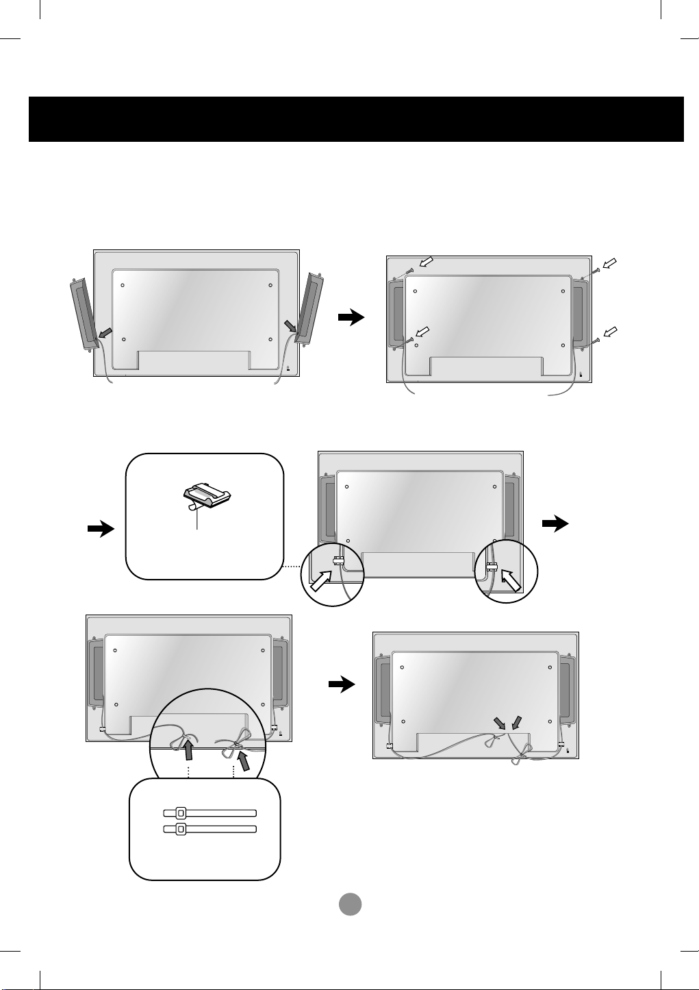
Connecting the Speakers
- Only on some models.
Mount the product onto the speaker by using a screw as shown in the following
connect the speaker cable.
After installing your speakers, use holders and cable ties to organize the speaker cables.
Cable holder
Remove the paper.
* This feature is not available in all model.
Cable tie
* This feature is not available in all model.
When the speaker is installed.
*Connect the input terminal with a proper color match.
2
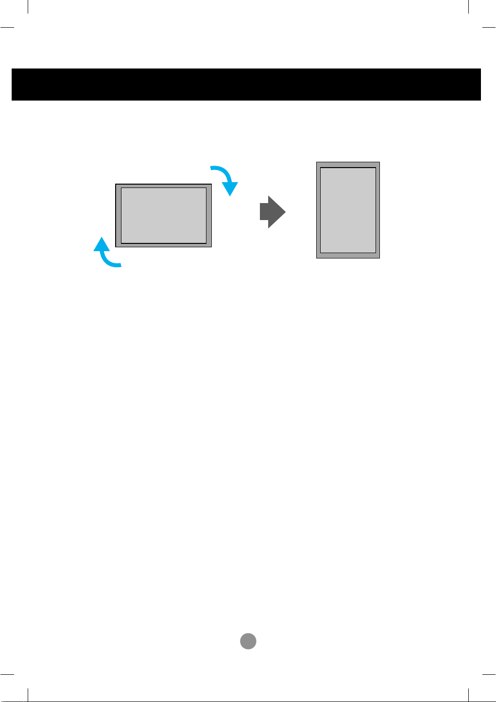
To install Portrait
- Only on some models.
"When installing Portrait, rotate it clockwise based on its front."
3
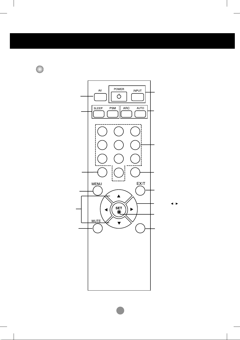
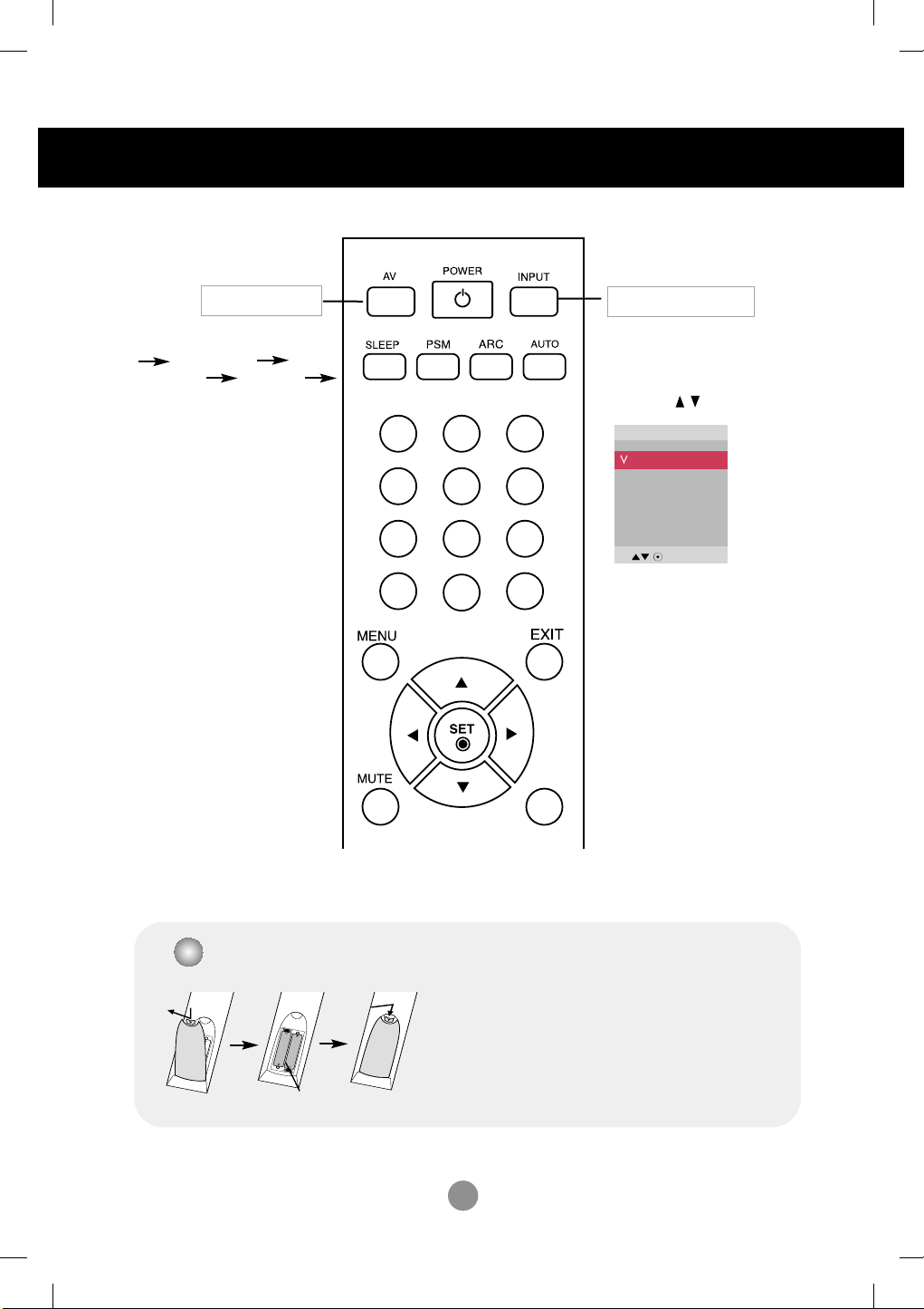
Using the Remote Control
Name of the Remote Control Buttons
•
AV Button
•
When watching AV, RGB PC,HDMI/DVI
,
Component1, Component2
The product will be automatically turned
off after a certain period of time.
Press this button repetitively to
select an appropriate time duration
- Toggles through preset video
Sleep Button
•
PSM Button
settings.
1 2 3
4 5 6
•
Power On/Off Button
•
Input Select Button
(See next page)
•
ARC button
Aspect Ratio Correction. Toggles
through aspect ratio options.
•
Auto Button
Automatic adjustment function
(Operational for the analog signal only)
There is not a function
which is supported
There is not a function
which is supported
•
Menu Button
•
UP and Down buttons
Bring up and down direction
adjustment.
•
Mute button
7 8
9
0
There is not a function
which is supported
•
Exit Button
•
Volume Button
Volume up and down
•
Check Button
*
There is not a function
which is supported
4
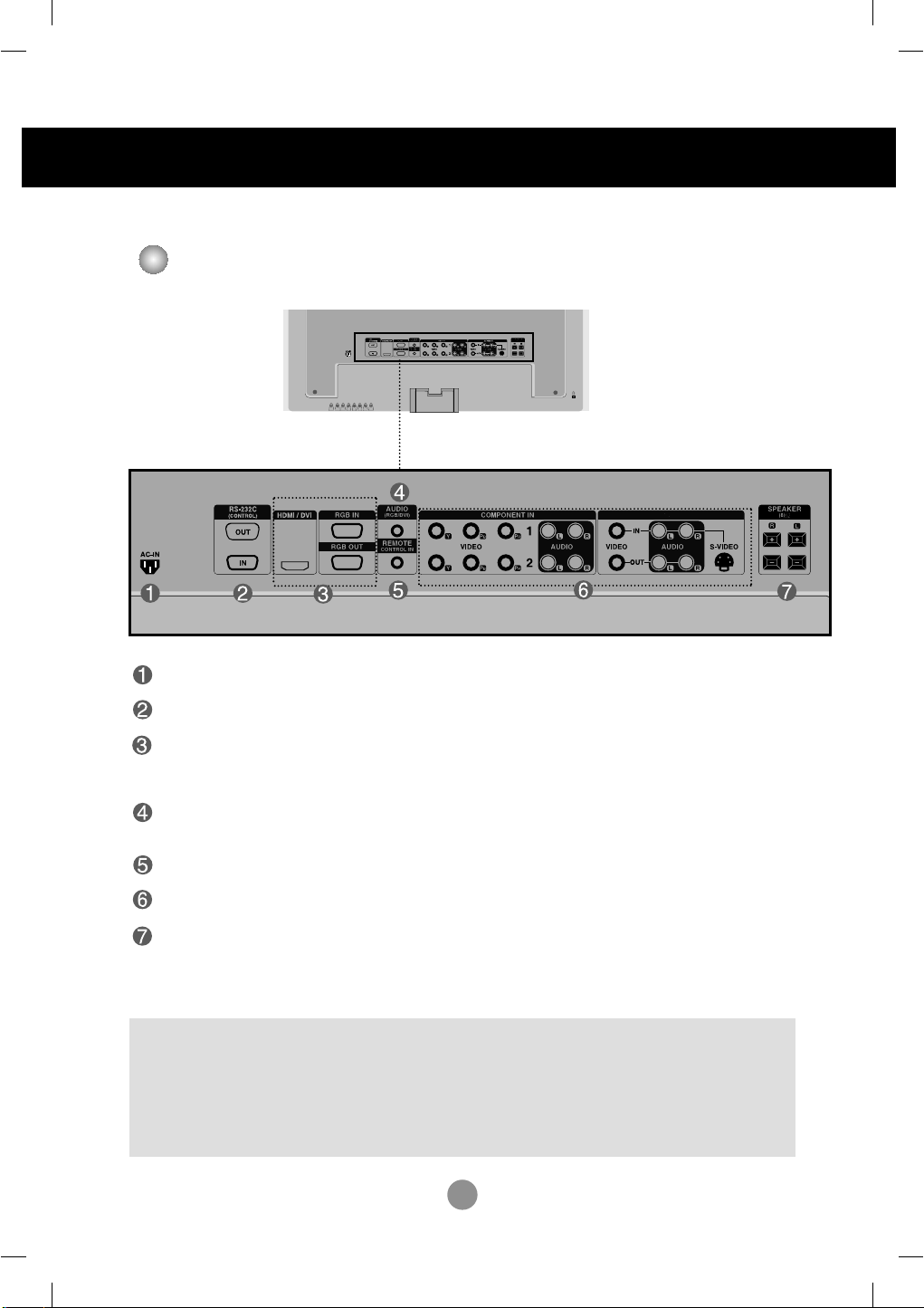
Name and Function of the Parts
AV IN/OUT
* The product image in the user’s guide could be different from the actual image.
Rear View
Power Connector : Connect the power cord
RS-232C Serial Ports
RGB PC, HDMI/DVI Ports
-HDMI Supports High Definition input and HDCP (High-bandwidth Digital Content
Protection). Some devices require HDCP in order to display HD signals.
PC Sound Jack
: Connect the audio cable to the *LINE OUT jack of the PC sound card.
Wired Remote Control Port
AV Ports
Speaker Ports
*LINE OUT
A terminal used to connect to the speaker including a built-in amplifier (Amp). Make sure that
the connecting terminal of the PC sound card is checked before connecting. If the Audio Out of
PC sound card has only Speaker Out, reduce the PC volume.
If the Audio Out of the PC sound card supports both Speaker Out and Line Out, convert to Line Out using
the card jumper of the program (Refer to the Sound Card Manual).
5
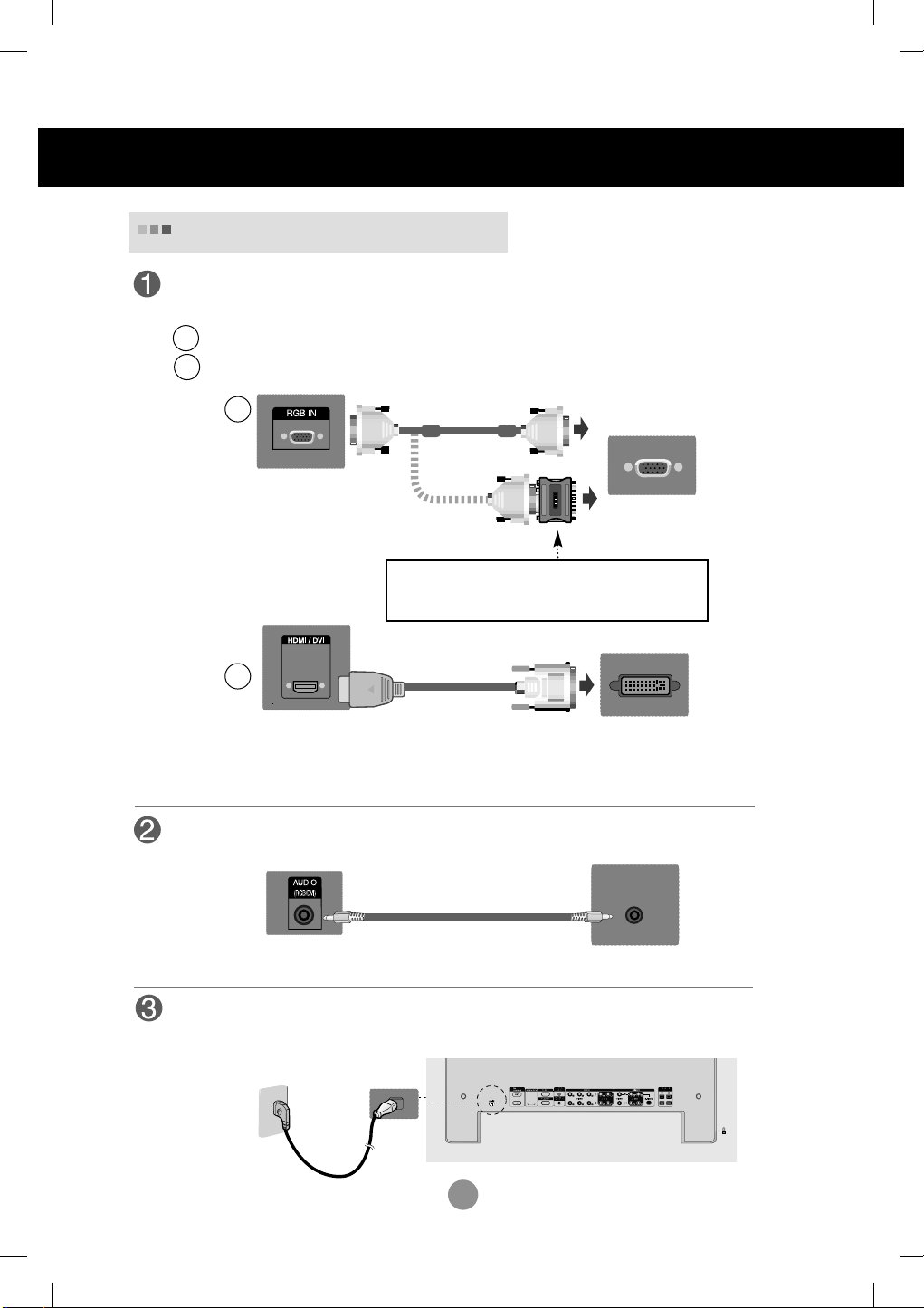
Connecting to External Devices
When Connecting to your PC
First of all, see if the computer, product and the peripherals are turned off.
Then, connect the signal input cable.
When connecting with the D-Sub signal input cable.
A
When connecting with the HDMI to DVI signal input cable (not included).
B
A
PC
Rear side of the product.
MAC
MAC
Macintosh Adapter (not included)
Use the standard Macintosh adapter since an incompatible
adapter is available in the market. (Different signaling system)
B
PC/
Rear side of the product.
* User must use shielded signal interface cables (D-sub 15 pin cable, DVI cable) with ferrite cores to maintain
standard compliance for the product.
(not included)
PC
Connect the Audio cable.
Rear side of the product.
PC
Connect the power cord.
Rear side of the product.
6
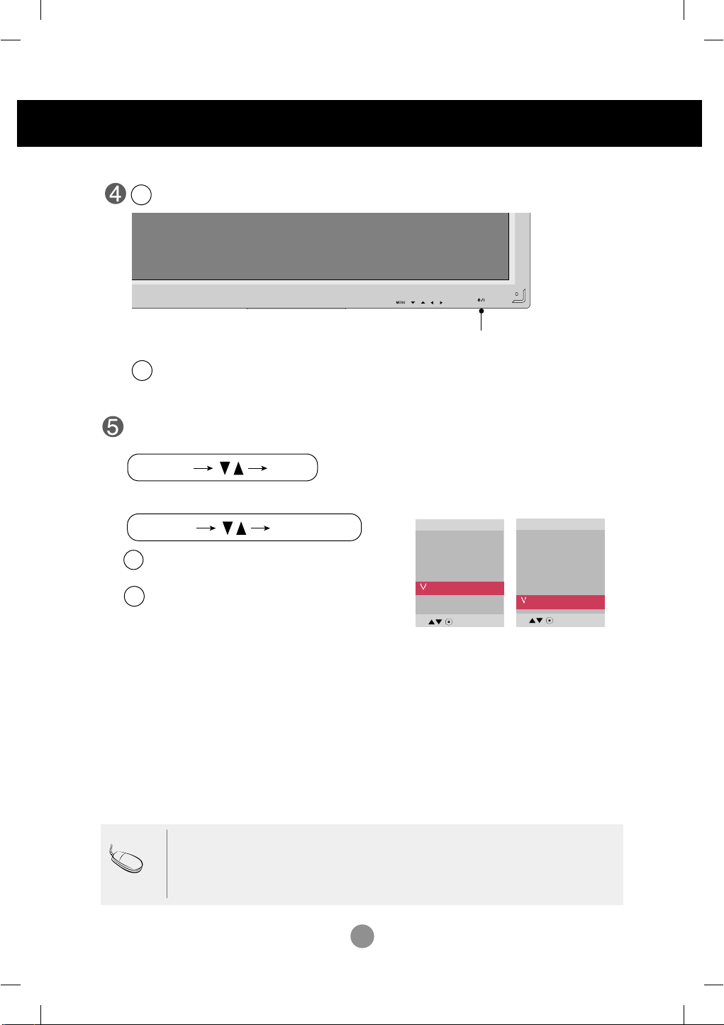
INPUT SET
SOURCE
AUTO/SET
Connecting to External Devices
Turn on power by pressing the power button on the product.
1
Turn on the PC.
2
SOURCE
AUTO/SET
ON/OFF
Power button
Select an input signal.
Press the INPUT button on the remote control to select the input signal.
Or, press the SOURCE button on the back of the product.
Input
AV
Component1
Component2
RGB PC
HDMI/DVI
When connecting with a D-Sub signal input cable.
A
• Select RGB PC : 15-pin
When connecting with a HDMI to DVI signal input cable.
B
• Select HDMI/DVI :
D-Sub
HDMI to DVI
analog signal.
Digital signal.
Input
AV
Component1
Component2
RGB PC
HDMI/DVI
Note
•
How to connect to two computers.
Connect the signal cables (
Press the INPUT button on the remote control to select the computer to use.
•
Directly connect to a grounded power outlet on the wall or a power bar with a ground
wire.
HDMI to DVI and D-Sub) to each computer.
7
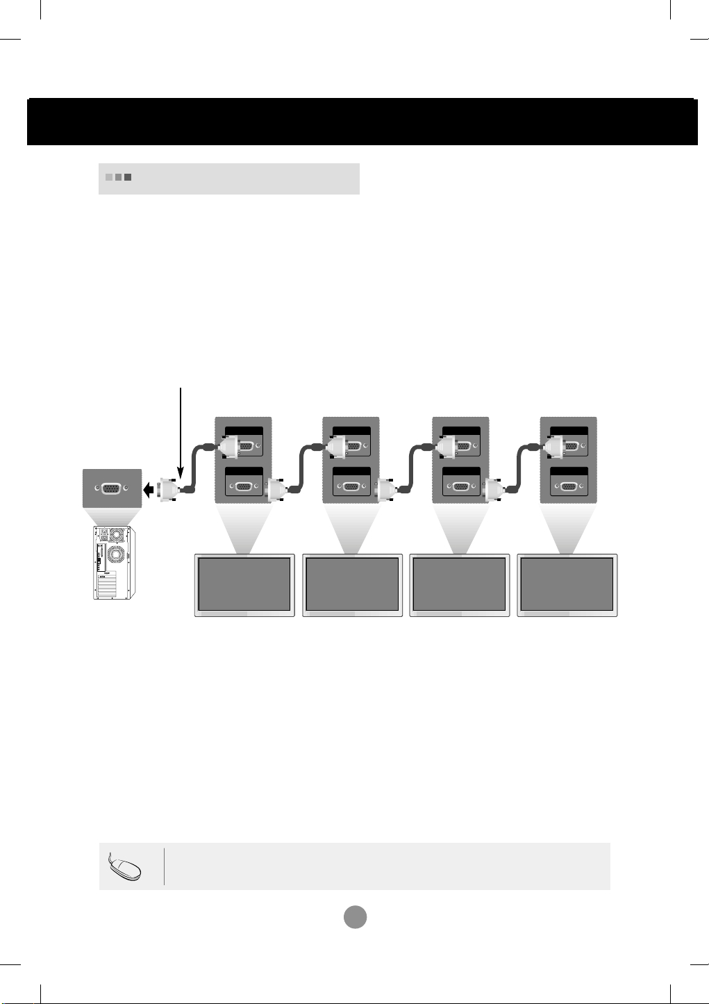
RGB IN
RGB OUT
RGB IN
RGB OUT
RGB IN
RGB OUT
RGB IN
RGB OUT
Connecting to External Devices
Daisy Chain Monitors
Use this function when displaying ANALOG RGB inputs of a PC to the other product.
•
To use different products connected to each other
Connect one end of the signal input cable(15-pin D-Sub Signal Cable) to the RGB OUT
connector of product 1 and connect the other end to the RGB IN connector of other
products.
15-pin D-Sub Signal Cable
PC
PC
Note
Product 2
Product 1
• When multi-connecting in/out cascade format, no loss cables are recommended.
Product 3
Product 4
We recommend that you should use cable distributor.
8
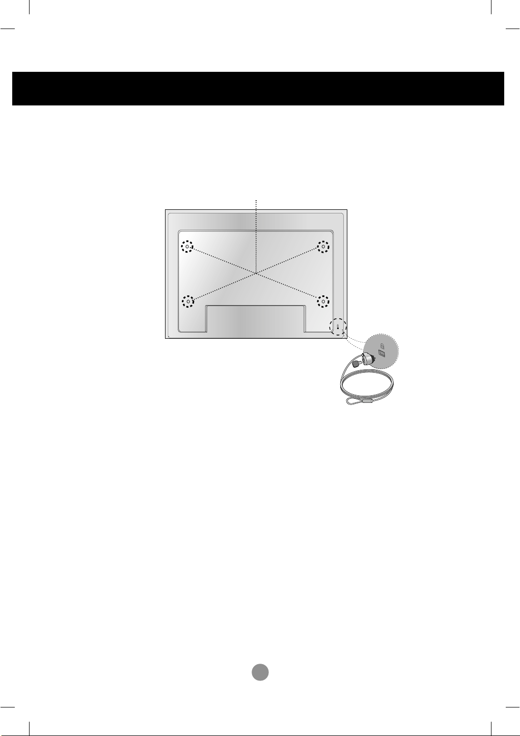
Connecting to External Devices
VESA FDMI wall Mounting
This product supports a VESA FDMI compliant mounting interface. These mounts are purchaed
separately and not available from LG. Refer to the instructions included with hte mount for more info.
The Set is equipped with a kensington Securify
System connector on the back panel. The cable and
lock are available separate and are not sold by LG.
For more info, visit http://www.kensington.com, the
internet home page of the Kensington company.
9
Using the Remote Control
1 2 3
4 5 6
7 8
0
9
*
•
AV Button
•
Input Select Button
Toggles through video
AV Component1
Component2 RGB PC
HDMI/DVI
If you press the button once,
the following Input Signal
Window will appear. Select
the signal type you want
using the button.
Input
AV
Component1
Component2
RGB PC
HDMI/DVI
Inserting batteries into remote control.
AAA Type
1. Slide off the battery cover.
2. Insert the batteries with correct polarity (+/-).
3. Close the battery cover.
• Dispose of used batteries in the recycle bin to prevent
environmental pollution.
10
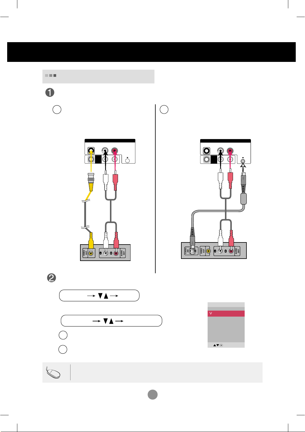
Connecting to External Devices
L-AUDIO-R
VIDEO
AV
OUT
AV IN
S-VIDEO
INPUT SET
SOURCE
AUTO/SET
L-AUDIO-R
VIDEO
AV
OUT
AV IN
S-VIDEO
Video Input
Connect the video cable as shown in the below figure and then connect the power
cord (See page 5).
When connecting with a BNC cable.
A
•
Connect the input terminal with a
proper color match.
When connecting with a S-Video cable.
B
•
Connect to the S-Video input terminal to
watch high image quality movies.
Product
Audio Cable
(not included)
BNC Cable
(not included)
VCR/DVD Receiver
Audio Cable
(not included)
VCR/DVD Receiver
Select an input signal.
Press the INPUT button on the remote control to select the input signal.
Or, press the SOURCE button on the back of the product.
When connecting with an BNC cable.
A
Select AV.
•
When connecting with an S-Video cable.
B
•
Select AV.
Product
Input
AV
Component1
Component2
RGB PC
HDMI/DVI
S-Video Cable
(not included)
Note
• When the BNC cable is connected simultaneously with S-Video cable, S-Video input has a priority.
11
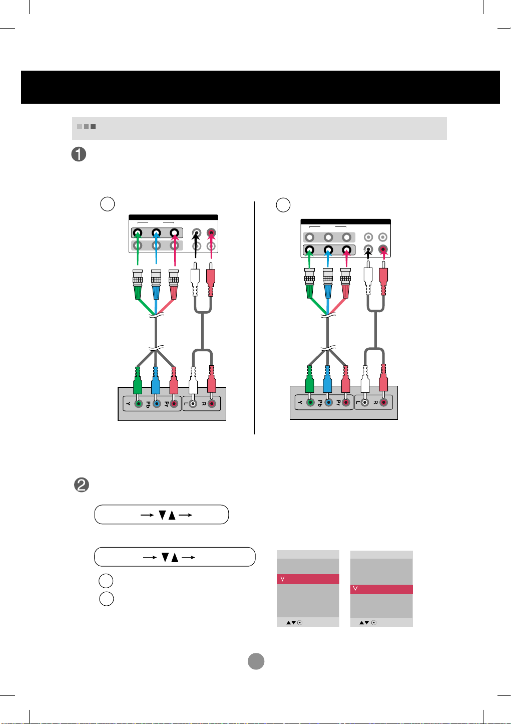
VIDEO
Y P
B
P
R
L-AUDIO-R
COMPONENT IN
1
2
INPUT SET
SOURCE
AUTO/SET
VIDEO
Y P
B
P
R
L-AUDIO-R
COMPONENT IN
1
2
Connecting to External Devices
Component Input (
480p/576p/720p/1080p/1080i/480i/576i)
Connect the video/audio cable as shown in the below figure and then, connect the
power cord (See page 5).
•
Connect the input terminal with a proper color match.
A
BNC Cable
(not included)
Product
Audio Cable
(not included)
B
BNC Cable
(not included)
Product
Audio Cable
(not included)
HDTV Receiver
HDTV Receiver
Note
- Some devices may require HDCP in order to display HD signals.
- Component doesn't support HDCP.
Select an input signal.
Press the INPUT button on the remote control to select the input signal.
Or, press the SOURCE button on the back of the product.
•
Select Component 1
A
•
Select Component 2
B
Input
AV
Component1
Component2
RGB PC
HDMI/DVI
12
Input
AV
Component1
Component2
RGB PC
HDMI/DVI
INPUT SET
SOURCE
AUTO/SET
Connecting to External Devices
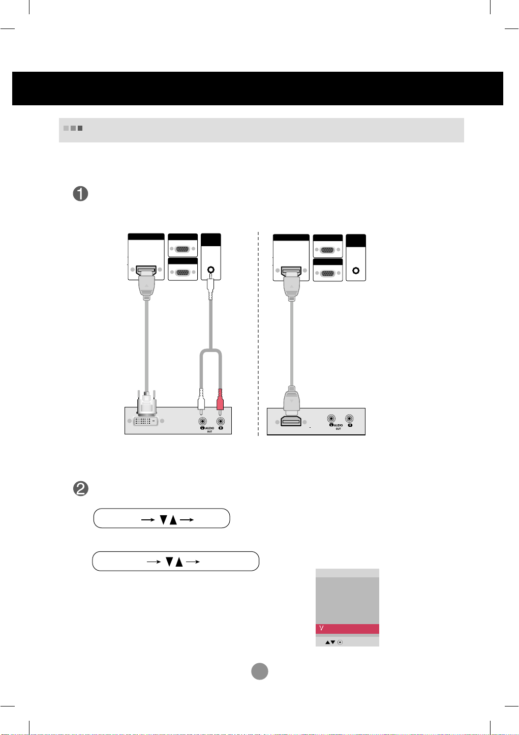
HDMI Input (480p/576p/720p/1080i/1080p)
-HDMI Supports High Definition input and HDCP (High-bandwidth Digital Content
Protection). Some devices require HDCP in order to display HD signals.
Connect the video/audio cable as shown in the below figure and then connect the
power cord (See page 5).
HDMI/DVI IN
RGB IN
RGB OUT
HDMI to DVI
Signal Cable
(not included)
VCR/DVD/Set-top Box
Product
AUDIO
(RGB/DVI)
RCA-PC
Audio Cable
Product
HDMI/DVI IN
RGB IN
AUDI O
(RGB/DVI)
RGB OUT
HDMI Signal Cable
(not included)
VCR/DVD/Set-top Box
Note : Dolby Digital is not supported.
Select an input signal.
Press the INPUT button on the remote control to select the input signal.
Or, press the SOURCE button on the back of the product.
Input
When connecting with a HDMI to DVI signal input cable.
When connecting with a HDMI signal input cable.
• Select HDMI/DVI
AV
Component1
Component2
RGB PC
HDMI/DVI
13
 Loading...