

Page 1

User's Guide
M4224N
M
ake sure to read the
Keep the User's Guide(CD) in an accessible place for future reference.
S
ee the label attached on the product and give the information to your dealer when you ask for
service.
Temporary noise is normal when powering ON or OFF this device.
WARNING -This is a class A product. In a domestic environment this product may cause radio
interference in which case the user may be required to take adequate measures.
Safety Precautions
Important
WARRANTY VOID
IF REMOVED
before using the product.
Warranty void if removed.
3850TAZ209Y
Page 2
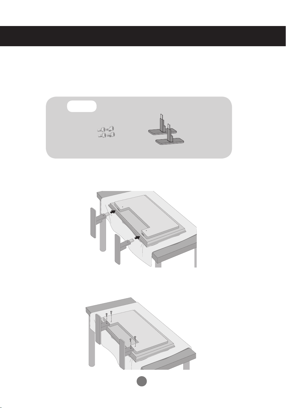
Connecting the stand
- Only on some models.
1.
Take the parts for the stand out of the box and assemble them as shown in the
picture.
Parts
2.
Place a soft cloth on the table and put the product with the screen facing downward. Connect the stand as shown in the following picture.
First, check if the following parts are all present.
Screws (4)
Stand (2)
3.
Use the screws to secure the stand on the rear side of the product as shown in
the diagram.
1
Page 3
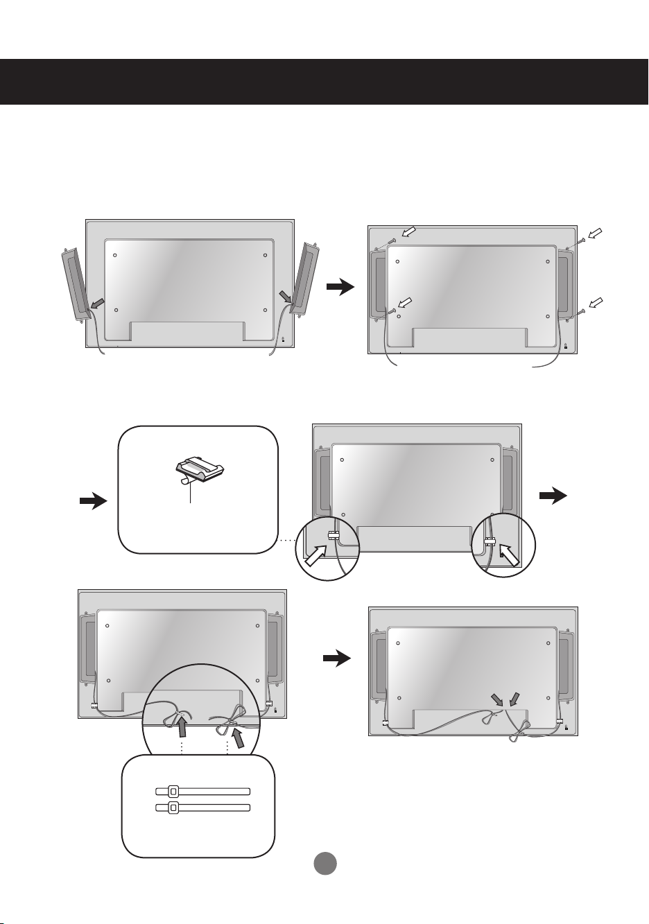
Connecting the Speakers
- Only on some models.
Mount the product onto the speaker by using a screw as shown in the following
connect the speaker cable.
After installing your speakers, use holders and cable ties to organize the speaker cables.
Cable holder
Remove the paper.
* This feature is not available in all model.
Cable tie
* This feature is not available in all model.
When the speaker is installed.
*Connect the input terminal with a proper color match.
2
Page 4
Using the Remote Control
1 2 3
4 5 6
7 8
0
9
CTR.
PWR
*
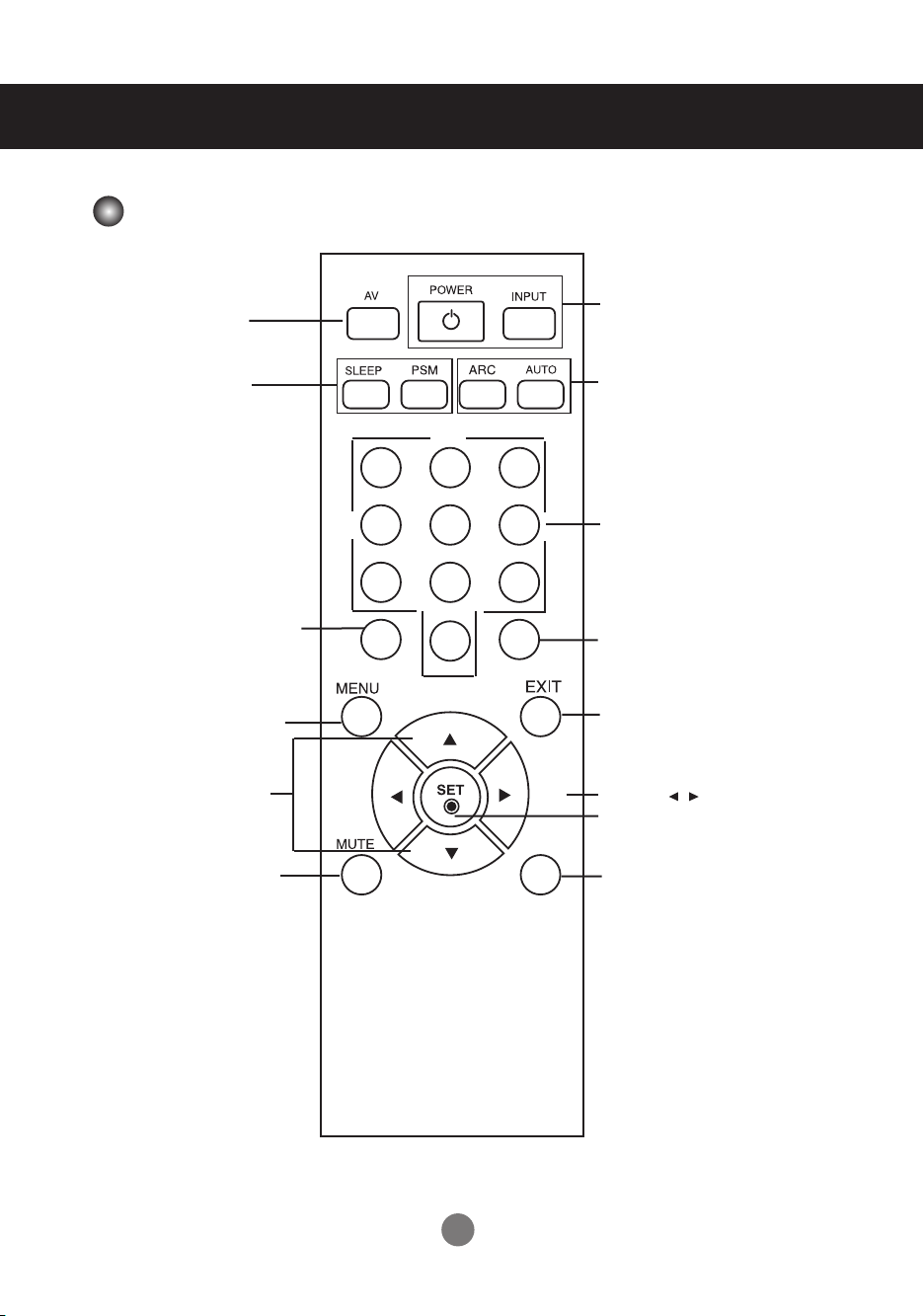
Name of the Remote Control Buttons
There is not a function
which is supported
There is not a function
which is supported
Turn on the power of the
(The CTR.PWR function
PC Control menu is off.)
▪ UP and Down buttons
Bring up and down direction
▪ CTR.PWR Button
PC built in the monitor
and then turn off.
operates only when the
▪ Menu Button
adjustment.
▪ Power On/Off Button
▪
Input Select Button
(See next page)
▪ ARC button
To select the image size
of the screen.
▪ Auto Button
Automatic adjustment
function (Operational for
the analog signal only)
There is not a function
which is supported
There is not a function
which is supported
▪ Exit Button
Volume Button
▪
▪ Check Button
▪ Mute button
There is not a function
which is supported
3
Page 5
Using the Remote Control
1 2 3
4 5 6
7 8
0
9
CTR.
PWR
*
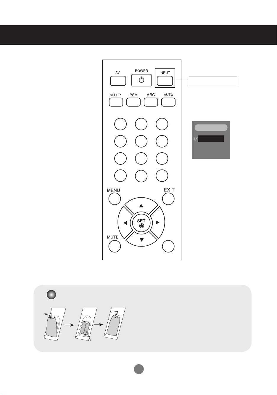
▪
Input Select Button
If you press the button once,
the following Input Signal
Window will appear. Select
the signal type you want
using the ▼▲ button.
INPUT
RGB
DVI
Inserting batteries into remote control.
1. Take out the battery cap.
2. Insert the batteries with correct polarity (+/-).
3. Close the battery cap.
▪ Dispose of used batteries in the recycle bin to prevent
environmental pollution.
AAA Type
4
Page 6
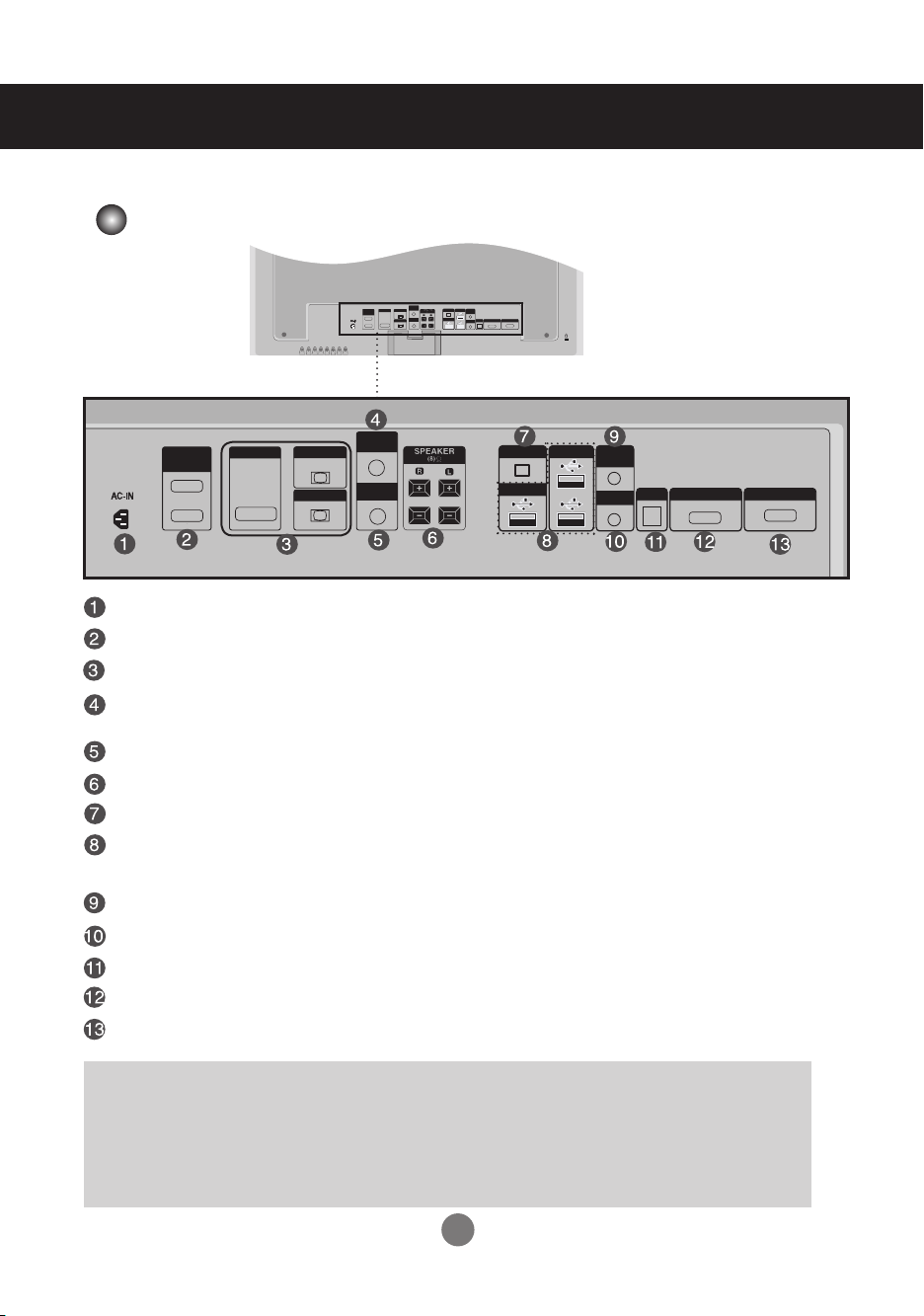
Name and Function of the Parts
RGB IN
OUT
IN
RGB IN
RGB OUT
DVI IN
RS-232C
(CONTROL)
AUDIO
(RGB/DVI)
REMOTE
CONTROL IN
LAN
USB
USB
H/PHONE
OUT
MIC IN
SP/DIF
SERIAL PORT
RGB OUT
RGB OUT
OUT
IN
RGB IN
RGB OUT
DVI IN
RS-232C
(CONTROL)
AUDIO
(RGB/DVI)
REMOTE
CONTROL IN
LAN
USB
USB
H/PHONE
OUT
MIC IN
SP/DIF
SERIAL PORT
RGB OUT
* The product image in the user’s guide could be different from the actual image.
Rear View
Power Connector : Connect the power cord
RS-232C Serial Ports (IN, OUT)
RGB, DVI Ports (IN, OUT)
PC Sound Jack
: Connect the audio cable to the *LINE OUT jack of the PC sound card.
ired Remote Control Port
Speaker Ports
LAN Ports
USB Ports :
Program installation and operation can be done by using USB Memory, USB HardDisk, USB CD-ROM, Keyboard (Wired or wireless), Mouse (wired or wireless), etc.
Head Phone out Port
MIC IN Ports
Optical Sound out Ports
Serial Ports
RGB out Ports
*LINE OUT
A terminal used to connect to the speaker including a built-in amplifier (Amp). Make sure
that the connecting terminal of the PC sound card is checked before connecting. If the
Audio Out of PC sound card has only Speaker Out, reduce the PC volume.
If the Audio Out of the PC sound card supports both Speaker Out and Line Out, convert
to Line Out using the card jumper of the program (Refer to the Sound Card Manual).
5
Page 7
Connecting to External Devices
OUT
IN
RGB IN
RGB OUT
DVI IN
RS-232C
(CONTROL)
AUDIO
(RGB/DVI)
REMOTE
CONTROL IN
LAN
USB
USB
H/PHONE
OUT
MIC IN
SP/DIF
SERIAL PORT
RGB OUT
OUT
IN
RGB IN
RGB OUT
DVI IN
RS-232C
(CONTROL)
AUDIO
(RGB/DVI)
REMOTE
CONTROL IN
AUTO/SET
SOURCE
SOURCE
MENU
INPUT
SET
INPUT
SOURCE
SET
AUTO/SET
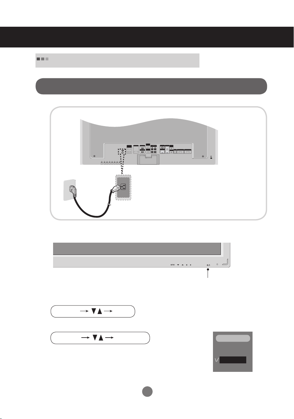
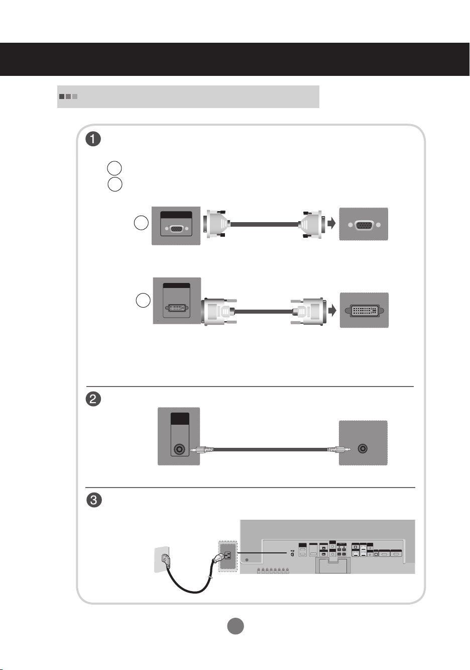
When Connecting to your Built in PC
When connecting with the DVI signal input
1.
Rear side of the product.
Connect the power cord.
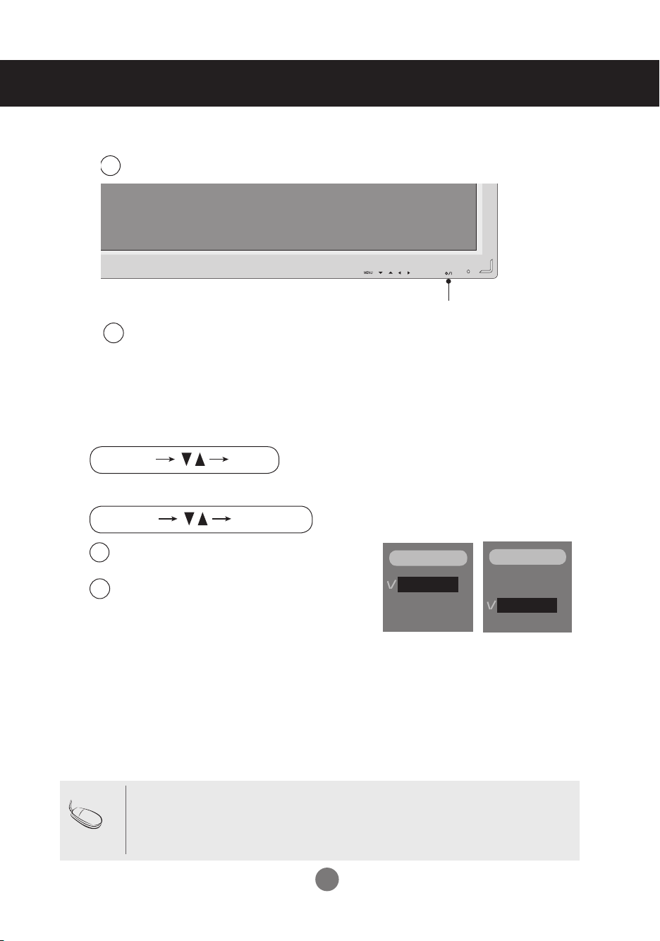
2.
Turn on power by pressing the power button on the product.
Power button
3.
Select an input signal.
Press the INPUT button on the remote control to select the input signal.
Or, press the SOURCE button at the back side of the product.
▪ Select DVI :
DVI
Digital signal.
6
INPUT
RGB
DVI
Page 8
Connecting to External Devices
AUTO/SET
SOURCE
SOURCE
MENU
RGB IN
OUT
IN
RGB IN
RGB OUT
DVI IN
RS-232C
(CONTROL)
AUDIO
(RGB/DVI)
REMOTE
CONTROL IN
LAN
USB
USB
H/PHONE
OUT
MIC IN
SP/DIF
SERIAL PORT
RGB OUT
RGB OUT
H/PHONE
OUT
RGB IN
AUDIO
(RGB/DVI)
REMOTE
CONTROL IN
OUT
IN
RGB IN
RGB OUT
DVI IN
RS-232C
(CONTROL)
AUDIO
(RGB/DVI)
REMOTE
CONTROL IN
LAN
USB
USB
H/PHONE
OUT
MIC IN
SP/DIF
SERIAL PORT
RGB OUT
OUT
IN
RGB IN
RGB OUT
DVI IN
RS-232C
(CONTROL)
AUDIO
(RGB/DVI)
REMOTE
CONTROL IN
LAN
USB
USB
H/PHONE
OUT
MIC IN
SP/DIF
SERIAL PORT
RGB OUT
RGB IN
OUT
IN
RGB IN
RGB OUT
DVI IN
RS-232C
(CONTROL)
AUDIO
(RGB/DVI)
REMOTE
CONTROL IN
LAN
USB
USB
H/PHONE
OUT
MIC IN
SP/DIF
SERIAL PORT
RGB OUT
OUT
IN
RGB IN
RGB OUT
DVI IN
RS-232C
(CONTROL)
AUDIO
(RGB/DVI)
REMOTE
CONTROL IN
LAN
USB
USB
H/PHONE
OUT
MIC IN
SP/DIF
SERIAL PORT
RGB OUT
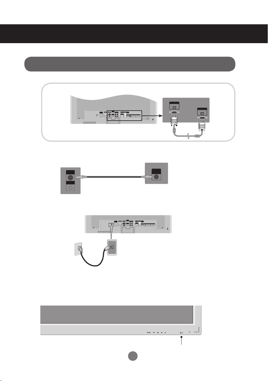
When connecting with the D-Sub signal input cable.
1.
2.
3.
Rear side of the product.
Rear side of the product.
Connect the Audio Cable
Rear side of the product.
Rear side of the product.
Connect the Power Cord
* User must use shielded signal interface cables (D-sub 15 pin cable, DVI cable) with ferrite cores to maintain standard compliance for the product.
Turn on power by pressing the power button on the product.
4.
7
Power button
Page 9
Connecting to External Devices
INPUT
SET
INPUT
SOURCE
SET
AUTO/SET
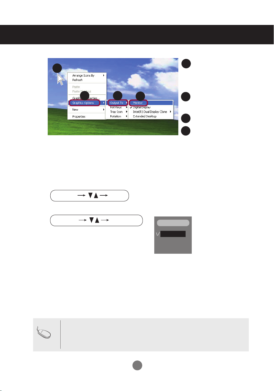
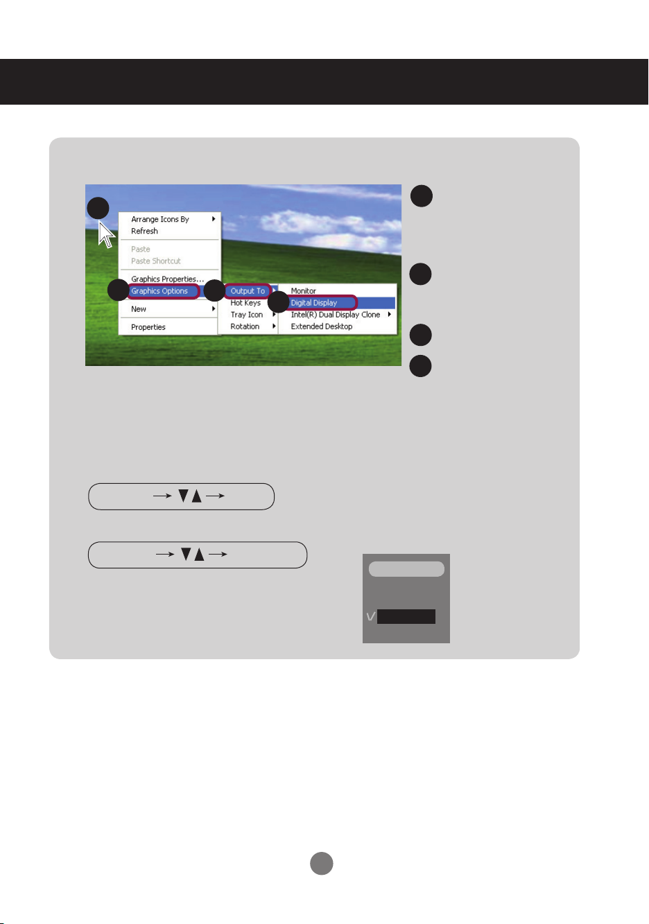
Move the mouse pointer
5.
6.
1
2
Select an input signal.
Press the INPUT button on the remote control to select the input signal.
Or, press the SOURCE button at the back side of the product.
3
4
1
to an empty area on the
Windows screen (with no
icons or task bars) and
click the right mouse button.
2
When the pop-up menu
appears, click the
‘Graphics Options' menu.
3
click the 'Output To' menu.
4
click the 'Monitor' menu.
When connecting with a D-Sub signal input cable.
▪ Select RGB : 15-pin
▪
Note
How to connect to two computers.
Connect the signal cables (DVI and D-Sub) to each computer.
Press the INPUT button in a remote control to select the computer to use.
▪
Directly connect to a grounded power outlet on the wall or a power bar with a ground wire.
D-Sub
analog signal.
INPUT
RGB
DVI
8
Page 10
Connecting to External Devices
INPUT
SET
INPUT
SOURCE
SET
AUTO/SET
* In order to convert the RGB signal to the DVI signal
Move the mouse point-
1.
1
2
3
4
Select an input signal.
2.
Press the INPUT button on the remote control to select the input signal.
1
er to an empty area on
the Windows screen
(with no icons or task
bars) and click the right
mouse button.
2
When the pop-up menu
appears, click the
'Graphics Options' menu.
Click the 'Output To' menu.
3
Click the 'Digital Display'
4
menu.
Or, press the SOURCE button at the back side of the product.
INPUT
When connecting with a DVI signal input cable.
▪ Select DVI :
DVI
Digital signal.
9
RGB
DVI
Page 11
Connecting to External Devices
OUT
IN
RGB IN
RGB OUT
DVI IN
RS-232C
(CONTROL)
AUDIO
(RGB/DVI)
REMOTE
CONTROL IN
LAN
USB
USB
H/PHONE
OUT
MIC IN
SP/DIF
SERIAL PORT
RGB OUT
RGB IN
OUT
IN
RGB IN
RGB OUT
DVI IN
RS-232C
(CONTROL)
AUDIO
(RGB/DVI)
REMOTE
CONTROL IN
LAN
USB
USB
H/PHONE
OUT
MIC IN
SP/DIF
SERIAL PORT
RGB OUT
RGB IN
OUT
IN
RGB IN
RGB OUT
DVI IN
RS-232C
(CONTROL)
AUDIO
(RGB/DVI)
REMOTE
CONTROL IN
LAN
USB
USB
H/PHONE
OUT
MIC IN
SP/DIF
SERIAL PORT
RGB OUT
RGB OUT
DVI IN
RGB IN
OUT
IN
RGB IN
RGB OUT
DVI IN
RS-232C
(CONTROL)
AUDIO
(RGB/DVI)
REMOTE
CONTROL IN
LAN
USB
USB
H/PHONE
OUT
MIC IN
SP/DIF
SERIAL PORT
RGB OUT
OUT
IN
RGB IN
RGB OUT
DVI IN
RS-232C
(CONTROL)
AUDIO
(RGB/DVI)
REMOTE
CONTROL IN
LAN
USB
USB
H/PHONE
OUT
MIC IN
SP/DIF
SERIAL PORT
RGB OUT
OUT
IN
RGB IN
RGB OUT
DVI IN
RS-232C
(CONTROL)
AUDIO
(RGB/DVI)
REMOTE
CONTROL IN
LAN
USB
USB
H/PHONE
OUT
MIC IN
SP/DIF
SERIAL PORT
RGB OUT
When Connecting to your PC
1.
First of all, see if the computer, product and the peripherals are turned off.
Then, connect the signal input cable.
When connecting with the D-Sub signal input cable.
A
When connecting with the DVI signal input cable.
B
RGB IN
A
Rear side of the product.
DVI IN
PC
B
* User must use shielded signal interface cables (D-sub 15 pin cable, DVI cable) with ferrite cores
to maintain standard compliance for the product.
Connect the Audio cable.
Rear side of the product.
AUDIO
(RGB/DVI)
PC
Rear side of the product.
PC
Connect the power cord.
Rear side of the product.
10
Page 12
Connecting to External Devices
AUTO/SET
SOURCE
SOURCE
MENU
INPUT
SET
INPUT
SOURCE
SET
AUTO/SET
2.
3.
Turn on power by pressing the power button on the product.
1
Power button
Turn on the PC.
2
Select an input signal.
Press the INPUT button on the remote control to select the input signal.
Or, press the SOURCE button at the back side of the product.
When connecting with a D-Sub signal input cable.
A
▪ Select RGB : 15-pin
When connecting with a
B
▪ Select DVI :
D-Sub
DVI
Digital signal.
analog signal.
DVI signal input cable.
INPUT
RGB
DVI
INPUT
RGB
DVI
Note
▪
How to connect to two computers.
Connect the signal cables (DVI and D-Sub) to each computer.
Press the INPUT button in a remote control to select the computer to use.
▪
Directly connect to a grounded power outlet on the wall or a power bar with a ground wire.
11
Page 13
Connecting to External Devices
RGB IN
RGB OUT
RGB IN
RGB OUT
RGB IN
RGB OUT
RGB IN
RGB OUT
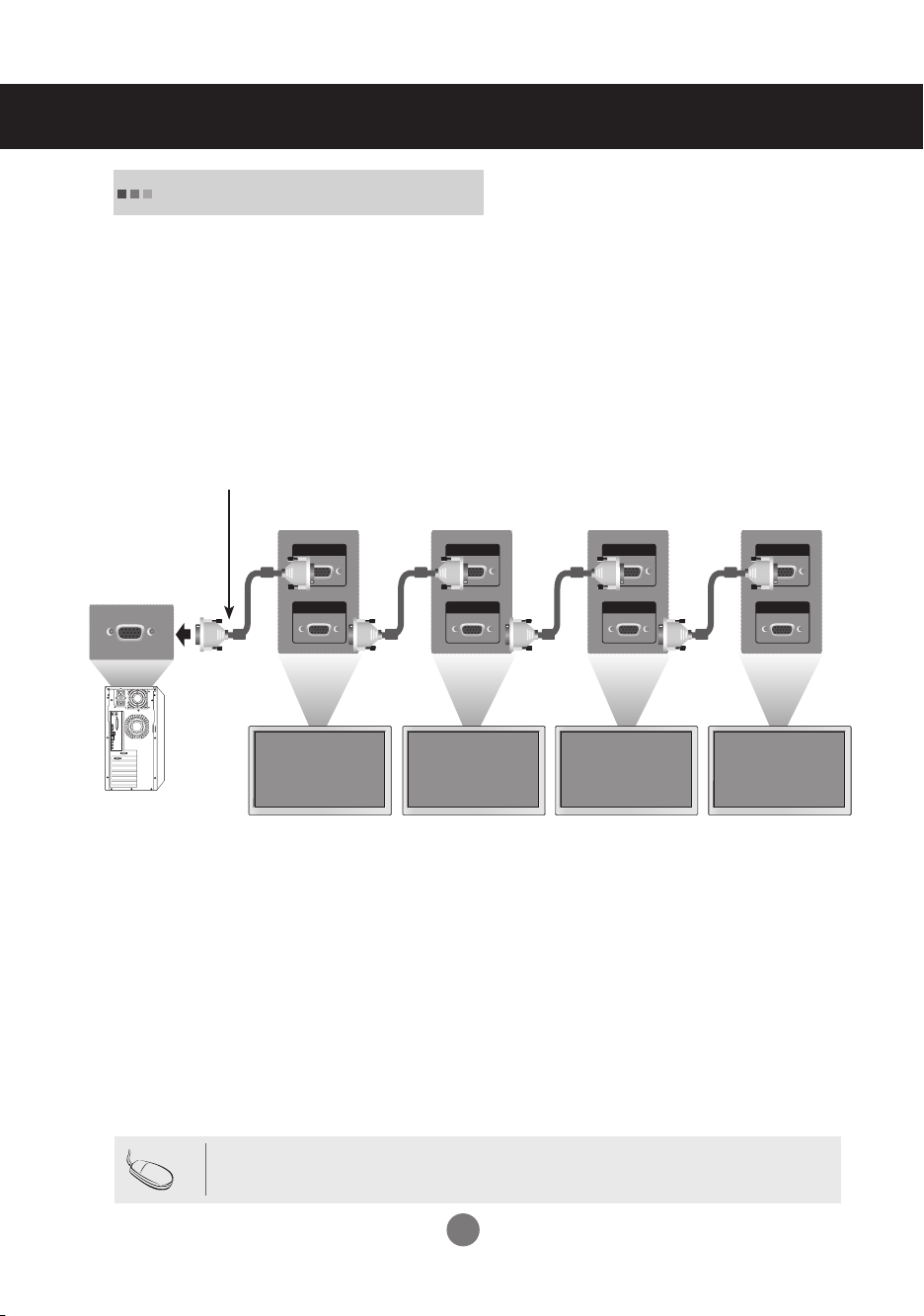
Watching RGB Outputs
Use this function when displaying ANALOG RGB inputs of a PC to the other product.
▪
To use different products connected to each other
Connect one end of the signal input cable(15-pin D-Sub Signal Cable) to the RGB OUT
connector of product 1 and connect the other end to the RGB IN connector of other
products.
15-pin D-Sub Signal Cable
PC
Note
Product 1
Product 2
Product 3
Product 4
▪ When multi-connecting in/out cascade format, cables to be less damaged are recommended.
We recommend that you should use cable distributor.
12
Page 14
Selecting and Adjusting the Screen
AUTO/SET
SOURCE
SOURCE
MENU
AUTO/SET
SOURCE
AUTO/SET
SOURCE
MENU
AUTO/SET
SOURCE
MENU
AUTO/SET
SOURCE
MENU
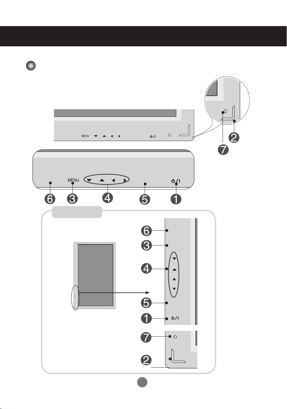
Name of the Buttons in the Screen Adjustment Unit
Pivot model Only
13
Page 15
Selecting and Adjusting the Screen
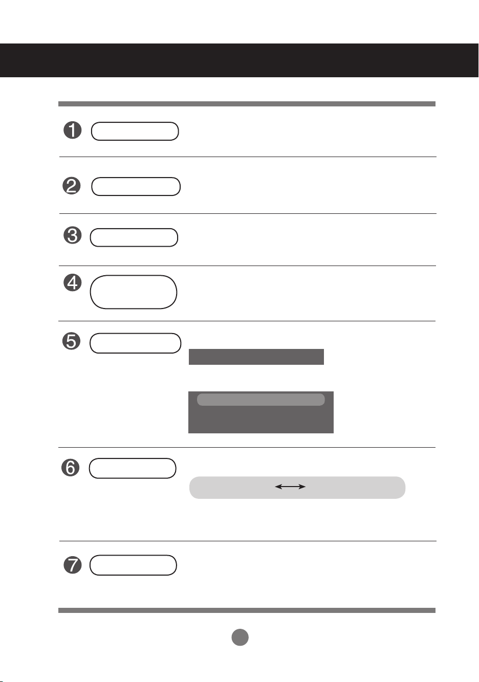
Power Button
Power Indicator
MENU Button
OSD Select /
Adjust Button
AUTO/SET Button
▪ Press this button to turn on the power. Press this button again
to turn it off.
▪ This Indicator lights up blue when the display operates
normally(on mode). If the display is in sleep (Power Saving)
mode, this indicator color changes to amber.
▪ Use this button to show/hide the OSD (On Screen Display)
menu screen.
▪
Use
this
button to select an icon or adjust the setting in the OSD screen.
If the resolution is 1920X1080 (RGB Mode)
Auto in progress
If the resolution is not 1920X1080 (RGB Mode)
Auto in progress
For optimal display
Change resolution to 1920 X 1080
SOURCE Button
IR Receiver
▪
Select the input signal
DVI (Digital signal) RGB(Analog signal)
Digital signal and Analogue signal can't be outputted at the same
time so when transferring the source connect the connector and
then turn on the power.
▪ The unit that receives the signal from the remote control.
14
Page 16
Selecting and Adjusting the Screen
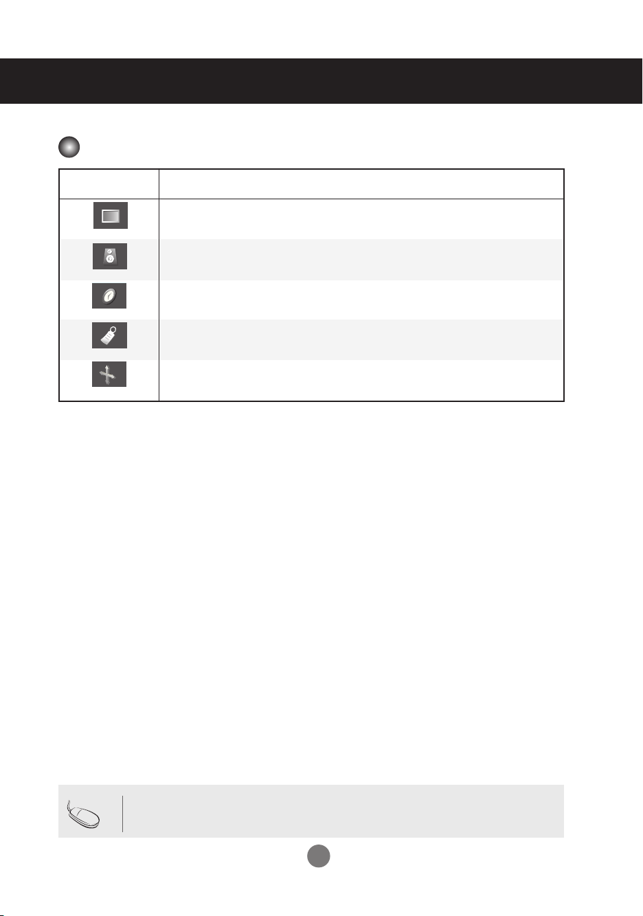
OSD Menu
Icon Function Description
Adjusts screen brightness, contrast and color that you prefer.
PICTURE
SOUND
TIMER
SPECIAL
SCREEN
Adjusts the audio function.
Adjust the time function
Adjusts the screen status according to the circumstances.
Adjusts the screen video.
Nota
▪ OSD (On Screen Display)
The OSD function enables you to adjust the screen status conveniently since it provides graphi-
cal presentation.
15
Page 17
Selecting and Adjusting the Screen
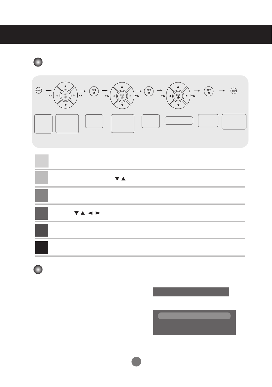
How to adjust the OSD (On Screen Display) screen
Pops up
the menu
screen
Move where
you want to
adjust
Press the MENU Button, then the main menu of the OSD appears.
1
To access a control, use the Buttons.
2
When the icon you want becomes highlighted, press the SET Button.
3
Use the Buttons to adjust the item to the desired level.
4
Accept the changes by pressing the SET Button.
5
Exit the OSD by pressing the EXIT Button.
6
Select a
menu icon
Move where
you want to
adjust
▪
Select a
menu icon
Use the remote control to adjust the OSD screen.
How to adjust the screen automatically
You need to adjust the screen display when connecting the product to a new computer or changing the
mode. Refer to the following section to set an optimal product screen.
Press the AUTO/SET button (AUTO button in a
remote Control) in the PC analog signal. Then, an
optimal screen status will be selected that fits into
the current mode.
If adjustment is not satisfactory, you need to adjust
screen position, clock and phase in the OSD menu.
If the resolution is 1920X1080 (RGB Mode)
If the resolution is not 1920X1080 (RGB Mode)
Change resolution to 1920 X 1080
Adjust the status
Auto in progress
Auto in progress
For optimal display
Save
adjustment
Exit from the
menu screen.
16
Page 18

Selecting and Adjusting the Screen
CSM
CSM
CSM
Adjusting Screen Color
CSM
▪ 6500K/9300K
Selecting a factory setting color set.
6500K: Slightly reddish white.
9300K: Slightly bluish white.
▪ User : Select this option to use the
Contrast
To adjust the contrast of the screen.
Brightness
To adjust the brightness of the screen.
Red / Green / Blue
Set your own color levels.
user-defined settings.
17
Page 19

Selecting and Adjusting the Screen
SSM
Balance
Flat
Music
Movie
Sports
User
SOUND
SSM
Balance
Flat
Music
Movie
Sports
User
SOUND
0
L
R
SOUND
SSM
Balance
Adjusting the audio function
SSM
Balance
The best sound tone quality will be
selected automatically depending
on the video type that you're currently watching.
▪ Flat : The most commanding and natural audio.
▪ Music : Select this option to enjoy the original sound when listening to the music.
▪ Movie : Select this option to enjoy sublime sound.
▪ Sports: Select this option to watch sports broadcasting.
▪ User : Select this option to use the user-defined audio settings.
Use this function to balance sound from
the left and right speakers.
Note
When connected to your computer and the 'SSM' setting in the audio menu is one of Flat,
Music, Movie or Sports, the available menus are Balance.
18
Page 20

Selecting and Adjusting the Screen
TIMER
Clock
MNT Off timer
MNT On timer
PC Off timer
PC On timer
TIME ID to adjust the time function
Clock
MNT Off timer/
MNT On timer
PC Off timer/
PC On timer
▪ Once the On or Off time is set, these functions operate daily at the preset time.
Note
▪ Off time function overrides On time function if they are set to the same time.
▪ The set must be in off mode for the On time to work.
This function is used to set up of current time.
You must set the time correctly before using On/Off time function.
1) Press the MENU button and then use
2) Press the
3
) Press
4
) Press
The default value is -- : --.
5) Press the OK/MENU button to save.
The Off time automatically switches the set to off mode at the pre-set time.
1) Press the MENU button and then use
2) Press the button and then use
3) Press the button and then use
4) Press the button and then use
5) Press the button and then use
6) Only On time function; Press the button and then
7) Press the OK/MENU button to save.
The Off time automatically switches the PC to off mode at the pre-set time.
(PC Off/On timer menu is activated only when PC Control in Special menu is off.)
1) Press the MENU button and then use
2) Press the button and then use
3) Press the button and then use
4) Press the button and then use
5) Press the button and then use
6) Press the OK/MENU button to save.
button and then use
button and then use button to set the hour(00~23).
button and then use button to set the minutes(00~59).
button to select the TIMER menu.
button to select the Clock menu.
button to select the TIMER menu.
button to select MNT Off time or MNT On time.
button to select On or Off.
button to set the hour(00~23).
button to set the minutes(00~59).
button to select the TIMER menu.
button to select PC Off time or PC On time.
button to select On or Off.
button to set the hour(00~23).
button to set the minutes(00~59).
button to adjust volume level
.
19
Page 21

Selecting and Adjusting the Screen
Reset
Reset
Reset
Selecting the options
Input
Child lock
Language
Power indicator
Transparency
If you press the button once, the following Input Signal Window will appear.
Select the signal type you want using
the button.
Use the buttons to select On or Off. The Set can be set up so that it can only be
used with the remote control. This feature can prevent unauthorized viewing.
In order to lock the OSD screen adjustment, set the Child lock tab to the 'On' position.
In order to unlock it, do the following :
* Push the MENU button on the remote control and set Child lock to the 'Off' position.
To choose the language in which the control names are displayed.
Use this function to set the power indicator on the front side of the product to On or Off.
If you set Off, it will go off. If you set On at any time, the power indicator will automati-
cally be turned on.
To adjust the transparency of the OSD menu screen.
20
Page 22

Selecting and Adjusting the Screen
Reset
Reset
0
Tile mode Off
H-Size
0
V-Size
H-Position
V-Position
ID
Reset
Reset
Selecting the options
To use this function
▪
- You can connect the product with several other products and use the Tile mode function.
Tile mode
▪
Tile mode
▪
H Size
▪
V Size
▪
H-Position
▪
V-Position
▪
Reset
▪
ID
It is used to enlarge the screen and also used
with several products to view screen,
Tile mode and choose Tile alignment and set the ID of the current product to set location.
Adjust the horizontal size of the screen taking into account the size of the bezel.
Adjust the vertical size of the screen taking into account the size of the bezel.
Adjust the horizontal position of the screen taking into account the size of the bezel.
Adjust the vertical position of the screen taking into account the size of the bezel.
Function to initialize and release Tile. All Tile setting are released when selecting.
Tile recall and the screen returns to Full screen.
Select the location of the Tile by setting an ID.
21
Page 23

Selecting and Adjusting the Screen
Selecting the options
▪
Tile mode
-
Tile mode : row x column ( r = 1, 2, 3, 4 c = 1, 2, 3, 4)
- 4 x 4 available.
- Configuration of an integration screen is also available as well as configuration of one by one Display.
-
Tile mode (product 1 ~ 4) : r(2) x c(2)
row
ID1 ID2
-
Tile mode (product 1 ~ 9) : r(3) x c(3)
row
ID1 ID2 ID3
ID4 ID5 ID6
ID7 ID8 ID9
column
ID4
column
22
Page 24

Selecting and Adjusting the Screen
Reset
Reset
Set ID
PC Control
0
Tile mode Off
H-Size
0
V-Size
H-Position
1
V-Position
ID
ID
Reset
Reset
Selecting the options
▪
Tile mode (product 1 ~ 2) : r(2) x c(1)
row
ID1 ID2
column
Reset
Set ID
PC Control
Use this function to reset the product to the factory default. However, language selection
and PC Control selection will not be initialized.
You can assign a unique Set ID NO (name
assignment) to each product when several
products are connected for display. Specify
the number (1~99) using the button and
exit. Use the assigned Set ID to individually
control each product using the Product
Control Program.
You can change the power setting of the PC built in the monitor.
On : Turn on/off both the monitor and the built-in PC.
Off : Turn on/off the built-in PC only.
* How to turn on or off the PC built in the monitor after setting it to Off?
(a) Press the power button while the SOURCE button is being pressed on the rear side
of the monitor.
(b) Or, press the CTR.PWR button at the remote control.
23
Page 25

Selecting and Adjusting the Screen
Auto-configure
Auto-configure
Auto-configure
Auto-configure
Auto-configure
Auto-configure
0
H-Position
0
V-Position
Adjusting Screen CLOCK/PHASE and Position
ARC
Autoconfigure
Clock
Phase
Position
To select the image size of the screen.
(1:1 menu are not supported over 1920 X 1080 resolution)
This button is for the automatic adjustment of the screen position, clock and phase.
This function is suitable for analog signal input only.
To minimize any vertical bars or stripes visible on the screen background. The horizontal screen size will also change. This function is suitable for analog signal input
only.
To adjust the focus of the display. This item allows you to remove any horizontal noise
and clear or sharpen the image of characters. This function is suitable for analog
signal input only.
To adjust position of the screen.
This function is suitable for analog signal input
only.
24
Page 26

Troubleshooting
No image is displayed
●
Is the product power cord connected?
●
Is the power indicator light on?
●
Power is on, power
indicator
is green
but the screen appears extremely dark.
●
Is the power indicator amber?
●
Does the 'Out of range' message
appear?
●
Does the 'Power saving mode' On DVI
message appear?
●
Does the 'Check signal cable' message
appear?
▪ See if the power cord is properly connected to the
outlet.
▪ See if the power switch is turned on.
▪ Adjust brightness and contrast again.
▪ If the product is in power saving mode, move the
mouse or press any key.
▪ The signal from the PC (video card) is out of the
vertical or horizontal frequency range of the product. Adjust the frequency range by referring to the
Specifications in this manual.
* Maximum resolution
RGB : 1920 X
DVI :
1920 X
▪ Connect the RGB cable, and then change the
input source to 'RGB'.
And then, press the MENU button to set the PC
Control value of the SPECIAL menu to 'On'.
Disconnect RGB cable, and turn off the power, and
then turn on the power again.
▪ The signal cable between PC and product is not
connected. Check the signal cable.
▪ Press the 'INPUT' menu in the remote Control to
check the input signal.
1080
1080
@60Hz
@60Hz
●
Did you check the INPUT Key?
Note
* Vertical frequency: To enable the user to watch the product display, screen image should be
changed tens of times every second like a fluorescent lamp. The vertical frequency or refresh rate
is the times of image display per second. The unit is Hz.
* Horizontal frequency: The horizontal interval is the time to display one vertical line. When 1 is
divided by the horizontal interval, the number of horizontal lines displayed every second can be
tabulated as the horizontal frequency. The unit is kHz.
▪ Press the 'INPUT' menu in the remote Control to
check the input signal.
25
Page 27

Troubleshooting
The screen image looks abnormal.
●
Is the screen position wrong at the
RGB mode?
▪ Press the "AUTO" button in the remote control to
automatically select the optimal screen status that
fits into the current mode. If adjustment is not satisfactory, use the Position OSD menu.
▪ See if the video card resolution and frequency are
supported by the product. If the frequency is out of
range, set to the recommended resolution in the
Control Panel " Display " Setting menu.
●
Do thin lines appear on the background screen at the RGB mode?
●
Horizontal noise appears or the characters look blurred at the RGB mode.
●
The screen is displayed abnormally at
the RGB mode.
The audio function does not work.
●
No sound?
●
Sound is too dull.
●
Sound is too low.
▪ Press the "AUTO" button in the remote control to
automatically select an optimal screen status that
fits into the current mode. If adjustment is not satisfactory, use the Clock OSD menu.
▪ Press the "AUTO" button in the remote control to
automatically select an optimal screen status that
fits into the current mode. If adjustment is not satisfactory, use the Phase OSD menu.
▪ The proper input signal is not connected to the sig-
nal port. Connect the signal cable that matches with
the source input signal.
▪ See if the audio cable is connected properly.
▪ Adjust the volume.
▪ See if the sound is set properly.
▪ Select the appropriate equalize sound.
▪ Adjust the volume.
26
Page 28

Troubleshooting
'Child lock on' message appears.
● The 'Child lock on' message appears
when pressing the Menu button.
After-image appears on the product.
● After-image appears when the product is turned off.
Screen color is abnormal.
● Screen has poor color resolution
(16 colors).
● Do black spots appear on the screen?
Push the MENU button on the remote control and
set Child lock to the b position.
▪ If you use a fixed image for a long time, the pixels
may be damaged quickly. Use the screensaver
function.
▪ Set the number of colors to more than 32 bits (true
color)
Select Control Panel ─ Display ─ Settings ─ Color
Table menu in Windows.
▪ Several pixels (red, green, white or black color)
may appear on the screen, which can be attributable to the unique characteristics of the LCD
panel. It is not a malfunction of the LCD.
The operation does not work normally.
● The power suddenly turned off.
▪ Is the sleep timer set?
▪ Check the power control settings.
Power interrupted.
▪
"CAUTION! FAN STOP!"
If the power is turned off after this message appears,
it means that the fan is out of order.
In this case, contact your local service center.
27
Page 29

Specifications
The product specifications can change without prior notice for product improvement.
LCD Panel
Power
Dimensions
&Weight
42.02 inches (106.73 cm) TFT (Thin Film Transistor)
LCD (Liquid Crystal Display) Panel
Anti-Glare coating
Visible diagonal size: 106.73 cm
0.4845 mm x 0.4845 mm (Pixel Pitch)
Rated Voltage AC 100-240V~ 50/60Hz 3.0A
Power Consumption On Mode :
240W Typ.(Only Monitor)
Stand-by(Off Mode) : ≤ 1W(MNT OFF, PC OFF)
(Remote Comtrol DC OFF)
[1]
H
W
D
[3]
H
W
D
[2]
W
[4]
W
300W Typ.(
H
H
With PC
D
D
),
Width x Height x Depth
[1] 96.7 cm (38.07 inches) x 55.98 cm (22.04 inches) x 12.37 cm (4.87 inches)
[2] 96.7 cm (38.07 inches) x 55.98 cm (22.04 inches) x 12.37 cm (4.87 inches)
[3] 96.7 cm (38.07 inches) x 63.50 cm (25.00 inches) x 25.85 cm (10.18 inches)
[4] 96.7 cm (38.07 inches) x 63.50 cm (25.00 inches) x 25.85 cm (10.18 inches)
Net
[1] 20.0 kg (44.09 lbs) [2] 22.6 kg (49.82 lbs)
[3] 23.4 kg (51.59 lbs) [4] 26.0 kg (57.32 lbs)
NOTE
▪ Information in this document is subject to change without notice.
28
Page 30

Specifications
The product specifications can change without prior notice for product improvement.
Video Signal
Input Connector
Environmental
Conditions
Max. Resolution RGB:1920X
Recommended Resolution
DVI:1920X
Horizontal Frequency RGB:30-83kHz
DVI:30-83kHz
Vertical Frequency 56-60Hz(RGB/DVI)
Synchronization Type Separate/Composite/Digital
15-pinD-Subtype,DVI(Digital),RS-232C
Operational Condition Temperature:0˚C~40˚C,Humidity:10%~80%
Storage Condition Temperature:-20˚C~60˚C,Humidity:5%~95%
DVI:
1920X
dependingontheOSorvideocardtype.
RGB:1920X
dependingontheOSorvideocardtype.
* Applicable only for models that support the speakers
RMSAudioOutput 10W+10W(R+L)
Audio
InputSensitivity 0.7Vrms
SpeakerImpedance 8Ω
1080
@60Hz
1080@60Hz-Itmaynotbesupported
1080
@60Hz
1080
@60Hz
-Itmaynotbesupported
NOTE
Informationinthisdocumentissubjecttochangewithoutnotice.
29
Page 31

Specifications
PC Mode ─ Preset Mode
Horizontal
Preset mode
1 640 x 480 31.469 59.94
2 800 x 600 37.879 60.317
3 1024 x 768 48.363 60
4 1280 x 1024 63.981 60.02
5 1920 x 1080 67.5 60
Power
On Mode Blue
Sleep Mode Amber
Off Mode -
Indicator
Mode Pro duc t
Frequency
(kHz)
Vertical
Frequency
(Hz)
30
Page 32

Specifications
VESA wall mounting
Connected to another object (stand type and wall-mounted type.) This product accepts a
VESA-compliant mounting interface pad.- (This has to be purchased separately if required.)
For further information, refer to the VESA Wall Mounting Instruction Guide.
Kensington Security Slotseparately if required.)
Connected to a locking cable that can be purchased
separately at most computer stores
(This has to be purchased
31
Page 33

Specifications
PORT
USBH/PHONE
OUT
SP/DIF
Connecting the USB(Universal Serial Bus) Cable
"USB (Universal Serial Bus)" is an innovation in connecting your different desktop peripherals con-
veniently to your computer. By using the USB, you will be able to connect your mouse, keyboard,
and other peripherals to your display instead of having to connect them to your computer. This will
give you greater flexibility in setting up your system. USB allows you to connect a chain of up to 120
devices on a single USB port; and you can "hot" plug (attach them while the computer is running) or
unplug them while maintaining the Plug and the Plug auto detection and configuration. This display
has an integrated BUS-powered USB hub, allowing up to 2 other USB devices to be attached it.
1. Connect the upstream port of the display to the downstream port of the USB compliant PC or
another hub using the USB cable.
2. Connect the USB compliant peripherals to the downstream ports of the display.
USB downstream Port(3)
connect the cables from USB
compliant peripherals-such as
keyboard, mouse, etc
3.
The monitor's USB terminal supports USB 2.0 and High Speed cables.
High Speed Full Speed Low Speed
Data Rate 480Mbps 12Mbps 1.5Mbps
Power 2.5W 2.5W 2.5W
Consumption
(Max,each Port) (Max,each Port) (Max,each Port)
NOTE
To activate the USB hub function, the display must be connected to a USB compliant PC(OS) or
another hub with the USB cable(enclosed).
When connecting the USB cable, check that the shape of the connector at the cable side matches
the shape at the connecting side.
Even if the display is in a power saving mode, USB compliant devices will function when they are
connected the USB ports(both the upstream and downstream) of the display.
32
Page 34

RS-232C
Controlling the Multiple Product
Use this method to connect several products to a single PC.
You can control several products at a time by connecting them to a single PC.
Connecting the cable
Connect the RS-232C cable
* The RS-232C protocol is used for communication between the PC and prod-
uct. You can turn the product on/off, select an input source or adjust the
OSD menu from your PC.
Product 2 Product 3 Product 4Product 1
as shown in the picture.
RS-232C
(CONTROL)
OUT
IN
RS-232C Cable
(Not included)
RS-232C
(CONTROL)
OUT
IN
RS-232C Configurations
7-Wire Configurations (Standard RS-232C cable)
PC Monitor PC Monitor
RXD
2
TXD
3
5
GND
4
DTR
6
DSR
7
RTS
8
CTS
D-Sub 9 D-Sub 9
(Female) (Female)
TXD
3
RXD
2
GND
5
DSR
6
DTR
4
8
CTS
7
RTS
Communication Parameter
► Baud Rate : 9600buad Rate (UART)
► Data Length : 8bits
► Parity Bit : None
► Stop Bit : 1bit
► Flow Control : None
► Communication Code : ASCII code
► Use a crossed (reverse) cable
RS-232C
(CONTROL)
OUT
IN
RS-232C Cable
(Not included)
3-Wire Configurations (Not Standard)
RXD
TXD
GND
DTR
DSR
RTS
CTS
2
3
5
4
6
7
8
D-Sub 9 D-Sub 9
(Female) (Female)
RS-232C Cable
(Not included)
3
2
5
6
4
7
8
TXD
RXD
GND
DTR
DSR
RTS
CTS
RS-232C
(CONTROL)
OUT
IN
RS-1
Page 35

RS-232C
Controlling the Multiple Product
Command Reference List
COMMAND1 COMMAND1 DATA(Hexa)
01. Power k a 00H - 01H
02. Main Input Select k b 07H, 09H
03. Aspect Ratio k c 08H, 09H
04. Screen Mute k d 00H - 01H
05. Volume Mute k e 00H - 01H
06. Volume Control k f 00H - 64H
07. Contrast k g 00H - 64H
08. Brightness k h 00H - 64H
09. OSD Select k i 00H - 01H
10. Remote On/Off k m 00H - 01H
11. Balance k t 00H - 64H
12. Select Color Temp k u 00H - 02H
13. Auto Configure j u 01H
14. Red Gain Adjust j w 00H - 64H
15. Green Gain Adjust j y 00H - 64H
16. Blue Gain Adjust j z 00H - 64H
17. Tiling Mode d d 00H - 44H
18. Tile H Position d e 00H - 64H
19. Tile V Position d f 00H - 64H
20. Tile H Size d g 00H - 64H
21. Tile V Size d h 00H - 64H
22. Tile ID Set d i 00H - 10H
23. Temperature Check d n FFH
24. Inverter Adjust d r 00H - 01H
25. PC Power On/Off d s 00H - 01H
26. PC Control On/Off d t 00H - 01H
27. Input Select x b 06H, 08H
RS-2
Page 36

RS-232C
Controlling the Multiple Product
Protocollo trasmissione / ricezione
Transmission
[Command1][Command2][ ][Set ID][ ][Data][Cr]
* [Command 1]: First command. (k)
* [Command 2]: Second command. (a ~ u)
* [Set ID]: You can adjust the set ID to choose desired product
ID number in Special menu. Adjustment range is 1 ~99.
When selecting Set ID ‘0’, every connected
set is controlled. Set ID is indicated as decimal
(1~255) on menu and as Hexa decimal (0x0~0x64)
on transmission/receiving protocol.
* [DATA]: To transmit command data.
Transmit 'FF' data to read status of command.
* [Cr]: Carriage Return
ASCII code ‘0x0D’
* [ ]: ASCII code Space (0x20)’
OK Acknowledgement
[Command2][ ][Set ID][ ][OK][Data][x]
* The Product transmits ACK (acknowledgement) based on this format when
receiving normal data. At this time, if the data is data read mode, it indicates
present status data. If the data is data write mode, it returns the data of the PC
computer.
Error Acknowledgement
[Command2][ ][Set ID][ ][NG][Data][x]
* The Product transmits ACK (acknowledgement) based on this format when
receiving abnormal data from non-viable functions or communication errors.
Data 1: Illegal Code
2: Not supported function
3: Wait more time
RS-3
Page 37

RS-232C
Protocollo trasmissione / ricezione
01. Power On(Command : a)
►To control Power On/Off of the Set.
Transmission
[k][a][ ][Set ID][ ][Data][Cr]
Data 0 : Power Off 1 : Power On ff: Read Status
Acknowledgement
[a][ ][Set ID][ ][OK][Data][x]
►To show the status of Power On/Off.
Transmission
[k][a][ ][Set ID][ ][FF][Cr]
Data 0 : Power Off 1 : Power On ff: Read Status
Acknowledgement
[a][ ][Set ID][ ][OK][Data][x]
* The Product transmits ACK (Riconoscimento) based on this format when receiving normal
data. At this time, if the data is data read mode, it indicates present status data. If the data
is data write mode, it returns the data of the PC omputer.
Controlling the Multiple Product
02. Main input Select(Command : b) (Main Picture Input)
►To select input source for the Set.
You can also select an input source using the INPUT
button on the remote control.
Transmission
[k][b][ ][Set ID][ ][Data][Cr]
Data 7 : RGB
9 : DVI
Acknowledgement
[b][ ][Set ID][ ][OK][Data][x]
RS-4
Page 38

RS-232C
Controlling the Multiple Product
Protocollo trasmissione / ricezione
03. Aspect Ratio(Command : c) (Main picure format)
► To adjust the screen format.
You can also adjust the screen format using the ARC
(Aspect Ratio Control) button on remote control or in the Screen menu.
Transmission
[k][c][ ][Set ID][ ][Data][Cr]
Data 8 : Full mode
9 : 1:1 (
Acknowledgement
[c][ ][Set ID][ ][OK][Data][x]
04. Screen Mute(Command : d)
► To select screen mute on/off.
Operates only if current resolution is less than recommended resolution. )
Transmission
[k][d][ ][Set ID][ ][Data][Cr]
Data 0 : Screen mute off (Picture on)
1 : Screen mute on (Picture off)
Acknowledgement
[d][ ][Set ID][ ][OK][Data][x]
RS-5
Page 39

RS-232C
Controlling the Multiple Product
Protocollo trasmissione / ricezione
05. Volume Mute(Command : e)
► To control On/Off of the Volume Mute.
Transmission
[k][e][ ][Set ID][ ][Data][Cr]
Data 0 : Volume Mute On (Volume Off)
1 : Volume Mute Off (Volume On)
Acknowledgement
[e][ ][Set ID][ ][OK][Data][x]
Data 0 : Volume Mute On (Volume Off)
1 : Volume Mute Off (Volume On)
06. Volume Control(Command : f)
► To adjust Volume.
Transmission
[k][f][ ][Set ID][ ][Data][Cr]
Data Min : 00H ~ Max : 64H
(Hexadecimal code)
Acknowledgement
[f][ ][Set ID][ ][OK][Data][x]
Data Min : 00H ~ Max : 64H
·
Refer to ‘Real data mapping’ page RS-7.
RS-6
Page 40

RS-232C
Controlling the Multiple Product
Protocollo trasmissione / ricezione
07. Contrast(Command : g)
► To adjust screen contrast.
You can also adjust the contrast in the Picture menu.
Transmission
[k][g][ ][Set ID][ ][Data][Cr]
Data Min : 00H ~ Max : 64H
·
Refer to ‘Real data mapping’ as shown below.
Acknowledgement
[g][ ][Set ID][ ][OK][Data][x]
* Real data mapping
0 : Step 0
:
A : Step 10
:
F : Step 15
10 : Step 16
:
64 : Step 100
08. Brightness(Command : h)
To adjust screen brightness.
You can also adjust the brightness in the Picture menu.
Transmission
[k][h][ ][Set ID][ ][Data][Cr]
Data Min : 00H ~ Max : 64H
·
Refer to ‘Real data mapping’ as shown below.
Acknowledgement
[h][ ][Set ID][ ][OK][Data][x]
* Real data mapping
0 : Step
:
A : Step 10
:
F : Step 15
10 : Step 16
:
64 : Step 100
RS-7
Page 41

RS-232C
Controlling the Multiple Product
Protocollo trasmissione / ricezione
09. OSD Select(Command : l)
► To control OSD on/off to the set when RS-232C Commands are transmitted.
Transmission
[k][l][ ][Set ID][ ][Data][Cr]
Data 0 : OSD Off 1 : OSD On
Acknowledgement
[l][ ][Set ID][ ][OK][Data][x]
Data 0 : OSD Off 1 : OSD On
10. Remote On/Off (Command : m)
►
Lock the buttons at the rear side of the monitor and the button at the remote control.
Transmission
[k][m][ ][Set ID][ ][Data][Cr]
Data 0 : Off 1 : On
Acknowledgement
[m][ ][Set ID][ ][OK][Data][x]
Data 0 : Off 1 : On
11. Balance (Command : t)
► To adjust the sound balance.
Transmission
[k][t][ ][Set ID][ ][Data][Cr]
Data Min : 00H ~ Max : 64H
32H : Center 00H : Left 64H : Right
Acknowledgement
[t][ ][Set ID][ ][OK][Data][x]
Data Min : 00H ~ Max : 64H
32H : Center 00H : Left 64H : Right
RS-8
Page 42

RS-232C
Controlling the Multiple Product
Protocollo trasmissione / ricezione
12. Select Color Temp (Command : u)
► To adjust the screen color temperature.
Transmission
[k][u][ ][Set ID][ ][Data][Cr]
Data 0 : User
1 : 9300K
2 : 6500K
Acknowledgement
[u][ ][Set ID][ ][OK][Data][x]
Data 0 : User
1 : 9300K
2 : 6500K
13. Auto Configure(Command: j u)
► To adjust picture position and minimize image shaking
automatically. it works only in RGB(PC) mode.
Transmission
[j][u][ ][Set ID][ ][Data][Cr]
Data 1 : To set
Acknowledgement
[u][ ][Set ID][ ][OK][Data][x]
RS-9
Page 43

RS-232C
Controlling the Multiple Product
Protocollo trasmissione / ricezione
14. Red Gain Adjust (Command: j w)
► To adjust Red color level.
Transmission
[j][w][ ][Set ID][ ][Data][Cr]
Data Min : 00H ~ Max : 64H
Acknowledgement
[w][ ][Set ID][ ][OK][Data][x]
* When it is executed with the 6500K or 9300K selected, it is automatically changed to the USER.
15. Green Gain Adjust (Command: j y)
► To adjust Green color level.
Transmission
[j][y][ ][Set ID][ ][Data][Cr]
Data Min : 00H ~ Max : 64H
Acknowledgement
[y][ ][Set ID][ ][OK][Data][x]
* When it is executed with the 6500K or 9300K selected, it is automatically changed to the USER.
16. Blue Gain Adjust (Command: j z)
► To adjust Blue color level.
Transmission
[j][z][ ][Set ID][ ][Data][Cr]
Data Min : 00H ~ Max : 64H
Acknowledgement
[z][ ][Set ID][ ][OK][Data][x]
* When it is executed with the 6500K or 9300K selected, it is automatically changed to the USER.
RS-10
Page 44

RS-232C
Controlling the Multiple Product
Protocollo trasmissione / ricezione
17. Tiling Mode (Command :d d)
► Change a Tiling Mode..
Transmission
[d][d][ ][Set ID][ ][Data][Cr]
Data Description
00 Tiling mode is off.
12 1 x 2 mode(column x row)
13 1 x 3 mode
14 1 x 4 mode
... ...
44 4 x 4 mode
* The data can not be set to 0X or X0 except 00.
Acknowledgement
[d][ ][00][ ][OK/NG][Data][x]
18. Tile H Position (Command : d e)
► To set the horizontal position.
Transmission
[d][y][ ][Set ID][ ][Data][x]
Data Min : 00H ~ Max : 64H
(Hexadecimal code)
Acknowledgement
[e][ ][Set ID][ ][OK/NG][Data][x]
RS-11
Page 45

RS-232C
Controlling the Multiple Product
Protocollo trasmissione / ricezione
19. Tile V Position(Command : d f)
► To set the Vertical position.
Transmission
[d][f][][Set ID][][Data][x]
* The data range is from 00 to 64(in Hex).
Acknowledgement
[f][][Set ID][][OK/NG][Data][x]
20. Tile H Size(Command : d g)
► To set the Horizontal size.
Transmission
[d][g][][Set ID][][Data][x]]
* The data range is from 00 to 64(in Hex).
Acknowledgement
[g][][Set ID][][OK/NG][Data][x]
21. Tile V Size(Command : d h)
► To set the Vertical size.
Transmission
[d][h][][Set ID][][Data][x]
* The data range is from 00 to 64(in Hex).
Acknowledgement
[h][][Set ID][][OK/NG][Data][x]
RS-12
Page 46

RS-232C
Controlling the Multiple Product
Protocollo trasmissione / ricezione
22. Tile ID Set (Command : d i)
► To assign the Tile ID for Tiling function.
Transmission
[d][i][][Set ID][][Data][x]
* The data range is from 00 to 10 tile mode. (in Hex).
Acknowledgement
[i][][Set ID][][OK/NG][Data][x]
23. Temperature check (Command : d n)
► To read the inside temperature value.
Transmission
[d][n][][Set ID][][Data][x]
* The data is always FF(in Hex).
Acknowledgement
[n][][Set ID][][OK/NG][Data][x]
Data are 1 byte long in Hex ASCII format.
24. Inverter Adjust (Command : d r)
► To adjust the Inverter.
Transmission
[d][r][][Set ID][][Data][x]
Data 0 : Inverter Off
1 : Inverter On
Acknowledgement
[r][][Set ID][][OK/NG][Data][x]
RS-13
Page 47

RS-232C
Controlling the Multiple Product
Protocollo trasmissione / ricezione
25. PC Power On/Off (Command : d s)
► To turn On and Off the built in PC.
Transmission
[d][s][][Set ID][][Data][x]
Data 0 : PC Power Off
1 : PC Power On
Acknowledgement
[s][][Set ID][][OK/NG][Data][x]
*This operates only when ‘PC Control’ is ‘Off’.
26. PC Control On/Off (Command : d t)
► It sets the synchronized power on/off between the built-in PC of the monitor and the monitor.
Transmission
[d][t][][Set ID][][Data][x]
Data 0 : Off
1 : On
Acknowledgement
[t][][Set ID][][OK/NG][Data][x]
27. Input Selection (Command : b) (Main Picture Input)
► To select input source for the Set.
You can also select an input source using the INPUT button on the remote control.
Transmission
[x][b][ ][Set ID][ ][Data][Cr]
Data 06 : RGB
08 : DVI
Acknowledgement
[b][ ][Set ID][ ][OK][Data][x]
RS-14
Page 48

RS-232C
IR Codes
How to connect
► Connect your wired remote control to Remote Control port on the Product.
Remote Control IR Code
► Output waveform
single pulse, modulated with 37.917KHz signal at 455KHz
Carrier frequency
Tc
FCAR = 1/Tc = fosc/12
Duty ratio = T1/Tc = 1/3
► Configuration of frame
T1
· 1st frame
Lead
code
Low
custom code
C0 C1 C2 C3 C4 C5 C6 C7 C0 C1 C2 C3 C4 C5 C6 C7 D0 D1 D2 D3 D4 D5 D6 D7 D0 D1 D2 D3 D4 D5 D6 D7
High
custom code
Data code
· Repeat frame
Repeat code
Tf
► Lead code
9ms
4.5ms
0.55ms
► Repeat code
9ms
2.25ms
► Bit description
· Bit "0" · Bit "1"
0.56ms
0.56ms
Data code
1.12ms
► Frame interval : Tf
· The waveform is transmitted as long as a key is depressed.
Tf
Tf=108ms@455KHz
Tf
RS-15
2.24ms
Page 49

RS-232C
Controlling the Multiple Product
IR Codes
Code(Hexa) Function
00 ▲
01 ▼
02
03
08
C4
C5
09
0B INPUT
43 MENU
5B EXIT
44 SET
10
11
12
13
14
15
16
17
18
19
D5 RGB
C6 DVI
79 ARC
77 ARC (1:1)
AF AUTO CONFIC
VOL( ► )
VOL( ◄ )
POWER ON/OFF
POWER ON
POWER OFF
MUTE
Number Key 0
Number Key 1
Number Key 2
Number Key 3
Number Key 4
Number Key 5
Number Key 6
Number Key 7
Number Key 8
Number Key 9
Note
R/C Button
R/C Button
R/C Button
R/C Button
R/C Button (Power On/Off)
Discrete IR Code(Only Power On)
Discrete IR Code(Only Power On)
R/C Button
R/C Button
R/C Button
R/C Button
R/C Button
R/C Button
R/C Button
R/C Button
R/C Button
R/C Button
R/C Button
R/C Button
R/C Button
R/C Button
R/C Button
Discrete IR Code(Input RGB PC Selection)
Discrete IR Code(Input DVI Selection)
R/C Button
Discrete IR Code(Only
Discrete IR Code
1:1
mode)
RS-16RS-16
Page 50

EWF (Enhanced Write Filter) function
Definition
- Write protect function for more than one partition
- This is the function to protect the partition by returning to original condition prior to the
installation once rebooted after the data has been recorded or program installed
How to set
- Double click on the [EWF Enable] file in the [EWF] folder from the desktop and set to protect after auto reboot.
Double Click
*Setting from DOS mode
Click on [Start] ► [Run] ► [cmd] ► [ewfmgr c: -enable], and then reboot Windows.
E-1
Page 51

EWF (Enhanced Write Filter) function
How to cancel
- Double click the [EWF Disable] file in the [EWF] folder, and the DOS Window will be displayed to cancel the protection in 5 seconds.
Double Click
*Setting from DOS mode
►
[Start]
[Run] ► [cmd] ► [-commitanddisable -live]
How to check the current EWF condition
[Start] ► [Run] ► [cmd] ► [ewfmgr c:] ► Will be displayed as Enable or Disable.
E-2
Page 52

Windows backup and recovery using LG Smart Recovery
When Backing up the current OS from Windows
1. Select [Start] ► [LG Smart Recovery]
2. Select 'System Backup' ► Designate back up location to [D:] (Do not select C: as it is
where the OS is installed) ► After checking the file content, select 'OK'
3. Windows will automatically be rebooted ► Enter System Recovery Mode in DOS mode
► System backup will automatically start.
4. When completed, Windows will automatically reboot ► Select 'OK'
E-3
Page 53

Windows backup and recovery using LG Smart
Recovery
When Restoring the current OS from Windows
1. Select 'System Restore' ► Select after checking the backup file from LG Smart Recovery
(Factory image: Initial factory default image)
(Backup.LBI: User created image)
2. The system will automatically reboot and enter Recovery Mode ► System will auto-
matically be restored ► 'Select 'OK'
※ After windows restarts automatically, select on ‘Yes’ if a screen as shown below
appears then restart windows once again.
E-4
Page 54

Windows backup and recovery using LG Smart
Recovery
When Restoring the current OS from Windows
(When Windows cannot be booted)
1. When booting the system, press F11 on the keyboard to enter the Restore mode
2. Select 'System Restore' ► Select the backup file from LG Smart Recovery
(Factory image: Initial factory default image)
(Backup.LBI: User created image)
► After checking the image to restore, click on 'OK'
3. When the system is restored, click on OK'
※ After windows restarts automatically, select on ‘Yes’ if a screen as shown below
appears then restart windows once again.
E-5
Page 55

Limitation of Windows embedded XP
Limitation related to the installation of Microsoft Office
Embedded limitation of Microsoft Korean XP (Korean)
- When you run Full Screen (Alt+Enter) from the DOS window, the font can be broken.
- When saving the file with a different name from the Print window, the name of the menu
window is displayed in English.
- When moving to the detail menu item of Control panel etc., some menus are displayed
in English (HyperTerminal, Language setting by country etc.)
※ English versions, Office 2003/Office 2007, are all normally installed
E-6
 Loading...