

LG M228WDP-BZ, M198WDP-BZJ, M198WDP Owner's Manual

Please read this manual carefully before operating
your set.
Retain it for future reference.
Record model number and serial number of the set.
See the label attached on the back cover and quote
this information to your dealer when you require
service.
OWNER’S MANUAL
MM119988WWDDPP
MM222288WWDDPP
Trade Mark of the DVB Digital Video
Broadcasting Project (1991 to 1996)
IIDD NNuummbbeerr(( ss))::
5576 : M198WDP
5577 : M228WDP
1
PREPARATION
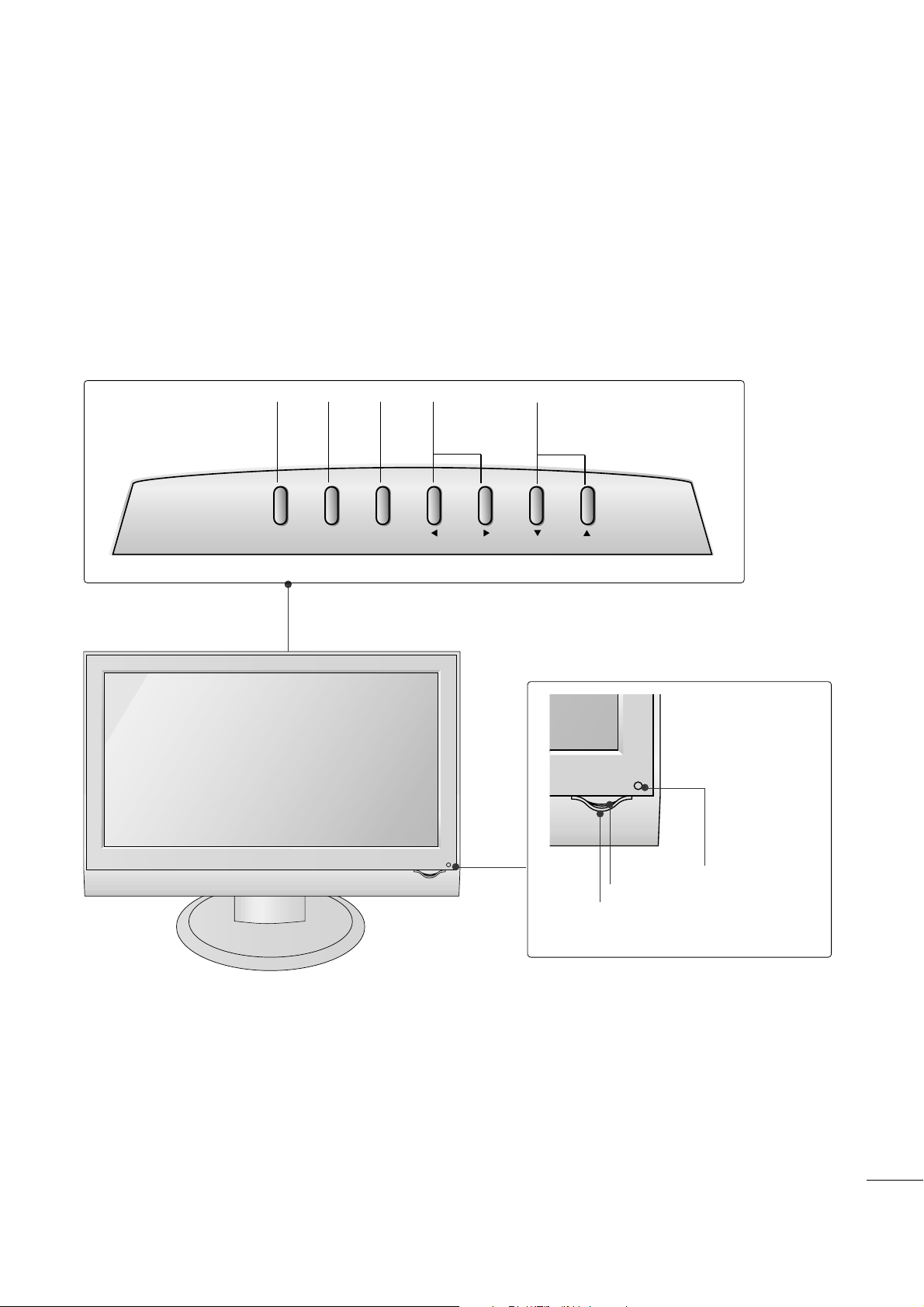
FRONT PANEL CONTROLS
■
This is a simplified representation of the front panel. The image shown may be somewhat different from your
set.
• Remote Control Sensor
• Power Indicator
• Power Sensor
PROGRAMME
Buttons
VOLUME
Buttons
MENU
Button
OK
Button
INPUT
Button
INPUT
MENU
VOL
PROK

2
PREPARATION
BACK PANEL INFORMATION
PCMCIA (Personal Computer Memory Card
International Association) Card Slot
(This feature is not available in all countries.)
Power Cord Socket
This set operates on AC power. The voltage is
indicated on the Specifications page. Never
attempt to operate the set on DC power.
HDMI/DVI Input
Connect a HDMI signal to HDMI IN.
Or DVI (VIDEO) signal to HDMI/DVI port with
DVI to HDMI cable.
RS-232C IN (CONTROL & SERVICE) PORT
Connect to the RS-232C port on a PC.
Antenna Input
Connect over-the-air signals to this jack.
Component Input
Connect a component video/audio device to
these jacks.
RGB/DVI Audio Input
Connect the monitor output from a PC to the
appropriate input port.
Euro Scart Socket (AV1/AV2)
Connect scart socket input or output from an
external device to these jacks.
RGB(PC) IN
Connect the output from a PC.
SERVICE ONLY PORT
1
2
3
4
5
6
7
8
9
10
■
This is a simplified representation of the back panel. The image shown may be somewhat different from your
set.
V 1
V 2
1
3 7
54
6
8
2
10
9
AV 1
AV 2
(CONTROL & SERVICE)
HDMI/DVI IN
RS-232C IN
COMPONENT IN
VIDEO
Y
PB
PR
AUDIO IN
(RGB/DVI)
RGB (PC) IN
AUDIO
LR
ANTENNA IN
SERVICE
ONLY
CARD SLOT
EJECT PCMCIA

3
PREPARATION
STAND INSTALLATION
■
The image shown may be somewhat different from your set.
1
2
3
4
Carefully place the product screen side down on a
cushioned surface that will protect product and
screen from damage.
Hold the
hhiinn gg ee bbooddyy
and pull it upward.
Hinge Body
Insert the
sstt aanndd bbooddyy
into the product until you
hear a clicking sound.
Stand Body
Assemble the parts of the
sstt aanndd bbooddyy
with
sstt aanndd bbaassee
of the product.
Stand Base
4
PREPARATION
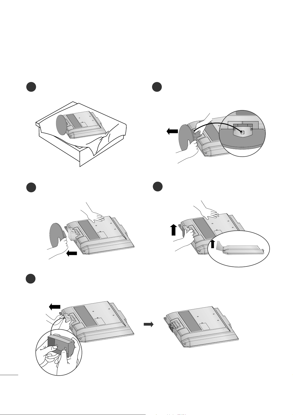
DETACHING STAND
1
2
3
Place the set screen side down on a cushion or
soft cloth.
Pull cover base backward while pressing button
on stand body.
Hold cover base and pull while shaking it backward to separate from stand body.
4
Hold the stand and pull it upward.
5
Pull stand body to separate from set while
pressing both latches.
■
The image shown may be somewhat different from your set.

5
PREPARATION
BACK COVER FOR WIRE ARRANGEMENT
Connect the cables as necessary.
To connect additional equipment, see the
EExxtteerrnnaall EEqquuiippmmeenntt SSeettuupp
section.
1
Install the
CCAABBLLEE MM AANNAAGGEEMMEENN TT
as shown.
2
First, press the cable management. Hold the
CCAABBLLEE MM AANNAAGGEEMMEENN TT
with both hands and pull it upward.
NOTE
!
GG
Do not hold the
CCAABBLLEE MM AANNAAGGEEMMEENN TT
when moving the product.
- If the product is dropped, you may be injured or the product may be broken.
How to remove the cable management
■
The image shown may be somewhat different from your set.

6
PREPARATION
WALL MOUNT: HORIZONTAL INSTALLATION
DESKTOP PEDESTAL INSTALLATION
For proper ventilation, allow a clearance of 4 inches on each side and from the wall.
For proper ventilation, allow a clearance of 4 inches on each side and from the wall. Detailed installation
instructions are available from your dealer, see the optional Tilt Wall Mounting Bracket Installation and
Setup Guide.
4 inches
4 inches
4 inches 4 inches
4 inches
4 inches
4 inches4 inches
4 inches
7
PREPARATION
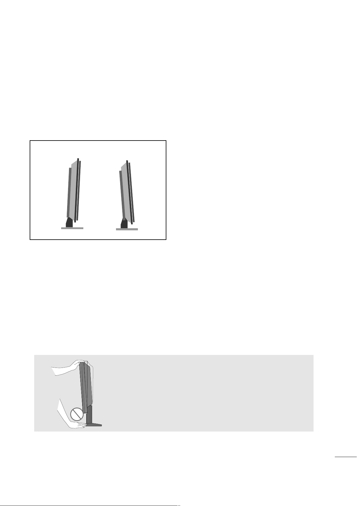
POSITIONING YOUR DISPLAY
■
The image shown may be somewhat different from your set.
Adjust the position of the panel in various ways for maximum comfort.
•• TTii lltt rraanngg ee
LOCATION
Position your set so that no bright light or sunlight falls directly onto the screen. Care should be taken
not to expose the set to any unnecessary vibration, moisture, dust or heat. Also, ensure that the set is
placed in a position to allow a free flow of air. Do not cover the ventilation openings on the back cover.
If you intend to mount the set to a wall, attach VESA standard mounting interface (optional parts) to the
back of the set.
When you install the set using the wall mounting bracket (optional parts), attach it carefully so it will not
drop.
0°~ 3
°
12°~8
°
WW aarrnnii nn gg ::
When adjusting the angle of the screen,do not put your
finger(s)in between the head of the monitor and the stand
body.You can hurt your finger(s).

8
PREPARATION
KENSINGTON SECURITY SYSTEM
- The product is equipped with a Kensington Security System connector on the back panel. Connect the
Kensington Security System cable as shown below.
- For detailed installation and use of the Kensington Security System, refer to the user’s guide provided with
the Kensington Security System.
For further information, contact
hhtttt pp:: //// wwwwww..kk eenn ss iinn gg ttoonn ..ccoo mm
, the internet homepage of the
Kensington company. Kensington sells security systems for expensive electronic equipment such as notebook PCs and LCD projectors.
NOTE
- The Kensington Security System is an optional accessory.
NOTES
a. If the product feels cold to the touch, there may be a small “flicker” when it is turned on.
This is normal, there is nothing wrong with product.
b. Some minute dot defects may be visible on the screen, appearing as tiny red, green, or blue spots.
However, they have no adverse effect on the monitor's performance.
c. Avoid touching the LCD screen or holding your finger(s) against it for long periods of time.
Doing so may produce some temporary distortion effects on the screen.
9
PREPARATION
AV 3
L/ MONO
R
AUDIO
VIDEO
S-VIDEO
AUDIO
VIDEO
AV 1 AV 2
ANTENNA
IN
EJECT
HDMI/DVI IN 1 HDMI IN 2
AV 3
L/ MONO
R
AUDIO
VIDEO
S-VIDEO
AUDIO
VIDEO
AV 1 AV 2
ANTENNA
IN
EJECT
HDMI/DVI IN 1 HDMI IN 2
■
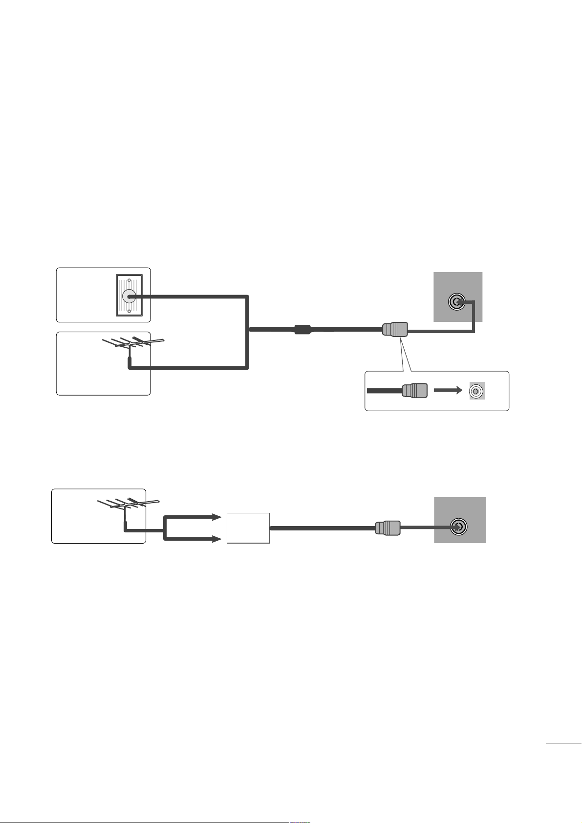
For optimum picture quality, adjust antenna direction.
■
An antenna cable and converter are not supplied.
■
To prevent equipment damage, never plug in any power cords until you have finished connecting all equipment.
Multi-family Dwellings/Apartments
(Connect to wall antenna socket)
Single-family Dwellings /Houses
(Connect to wall jack for outdoor antenna)
Outdoor
Antenna
(VHF, UHF)
Wall
Antenna
Socket
RF Coaxial Wire (75 ohm)
ANTENNA CONNECTION
Antenna
UHF
Signal
Amplifier
VHF
■
In poor signal areas, to get better picture quality, install a signal amplifier to the antenna as shown above.
■
If signal needs to be split for two TVs, use an antenna signal splitter for connection.
10
EXTERNAL EQUIPMENT SETUP
Connect the SET-TOP outputs to the
CCOOMMPPOONN EE NNTT IINN
VV IIDDEEOO
sockets (YP
B PR) on the set.
Connect the audio cable from the SET-TOP to
CCOOMMPP OO--
NNEE NNTT IINN AA UUDD IIOO
sockets of the set.
Press the
IINN PPUU TT
button to select Component.
2
3
1
HD RECEIVER SETUP
■
To prevent the equipment damage, never plug in any power cords until you have finished connecting all equipment.
■
The image shown may be somewhat different from your set.
When connecting with a component cable
Y
PBPR
LR
VIDEO
COMPONENT IN
AUDIO
1
2
Signal
480i/576i
480p/576p
720p/1080i
108 0p
Component
Yes
Yes
Yes
Yes
HDMI
No
Yes
Yes
Yes
11
EXTERNAL EQUIPMENT SETUP
When connecting with a HDMI
Connect the HDMI output of the digital set-top box to the
HH DDMMII//DDVVII IINN
jack on the set.
1
HDMI/DVI IN
1
Connect the digital set-top box to
HH DDMM II//DD VVII IINN
jack on the set.
Connect the audio output of the digital set-top box to
the
AAUUDDIIOO IINN ((RR GGBB//DDVVII ))
jack on the set.
Turn on the digital set-top box. (Refer to the owner’s
manual for the digital set-top box.
)
2
3
1
When connecting with a HDMI to DVI cable
DVI OUTPUT
AUDIO
RL
HDMI/DVI IN
AUDIO IN
(RGB/DVI)
1
2

12
EXTERNAL EQUIPMENT SETUP
DVD SETUP
When connecting with a component cable
AV 1 AV 2
Y
PBPRLR
VIDEO
COMPONENT IN
AUDIO
Component Input ports
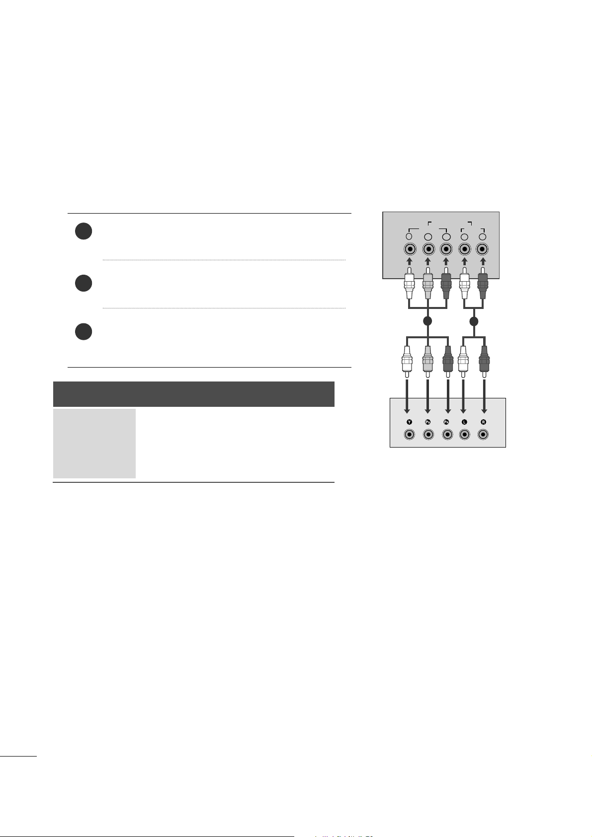
To get better picture quality, connect a DVD player to the component input ports as shown below.
Component ports on the set
YPB PR
Video output ports
on DVD player
Y
Y
Y
Y
P
B
B-Y
Cb
Pb
P
R
R-Y
Cr
Pr
Connect the video output sockets (YPBPR) of the DVD to
the
CCOOMMPPOO NNEENNTT II NN VVIIDDEEOO
sockets (YP
B
PR
) of the
set.
Connect the audio cable from the DVD to
CCOOMMPPOONNEE NNTT
IINN AAUUDDIIOO
sockets of the set.
Press the
IINN PPUU TT
button to select
Component.
Press the
PPLLAA YY
button on the DVD.
The DVD playback picture appears on the screen.
2
3
4
1
1 2
13
EXTERNAL EQUIPMENT SETUP
HDMI/DVI IN
AV 1 AV 2
(R) AUDIO (L)
AUDIO/
VIDEO
AV 1 AV 2
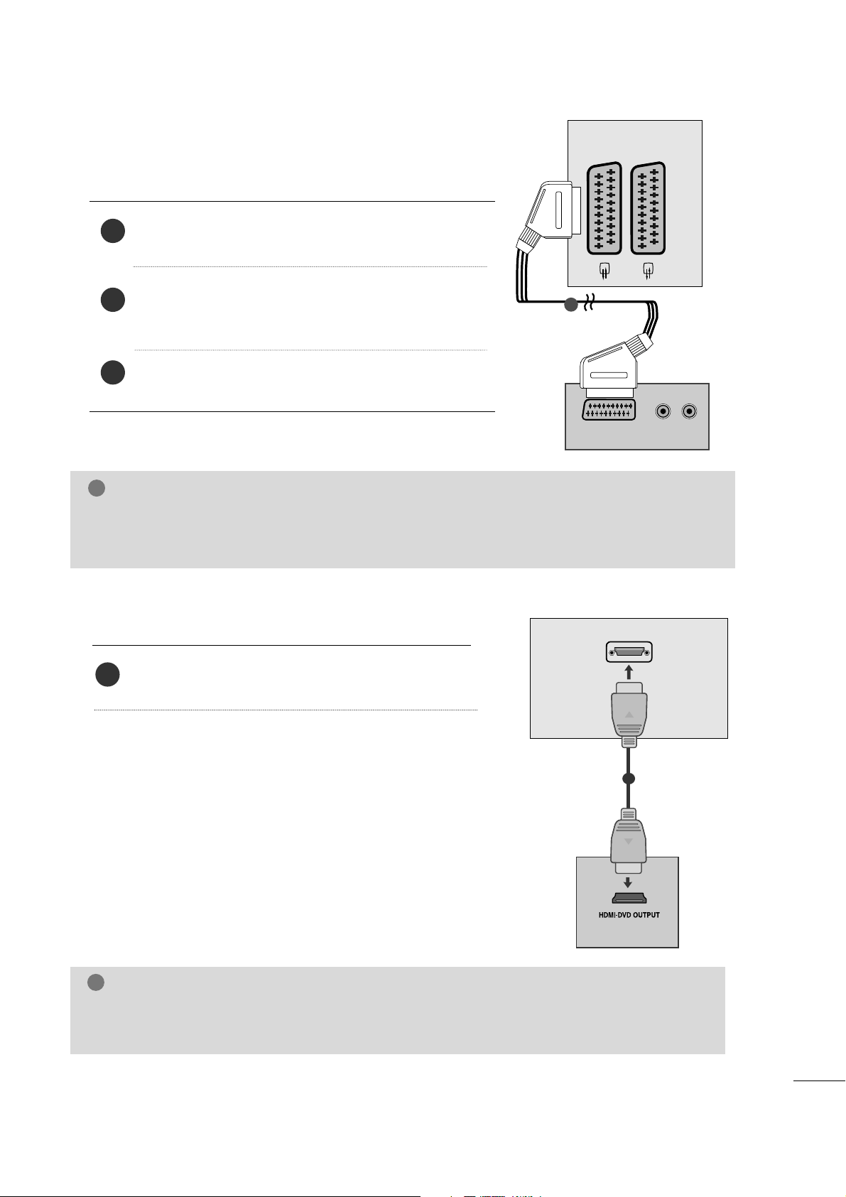
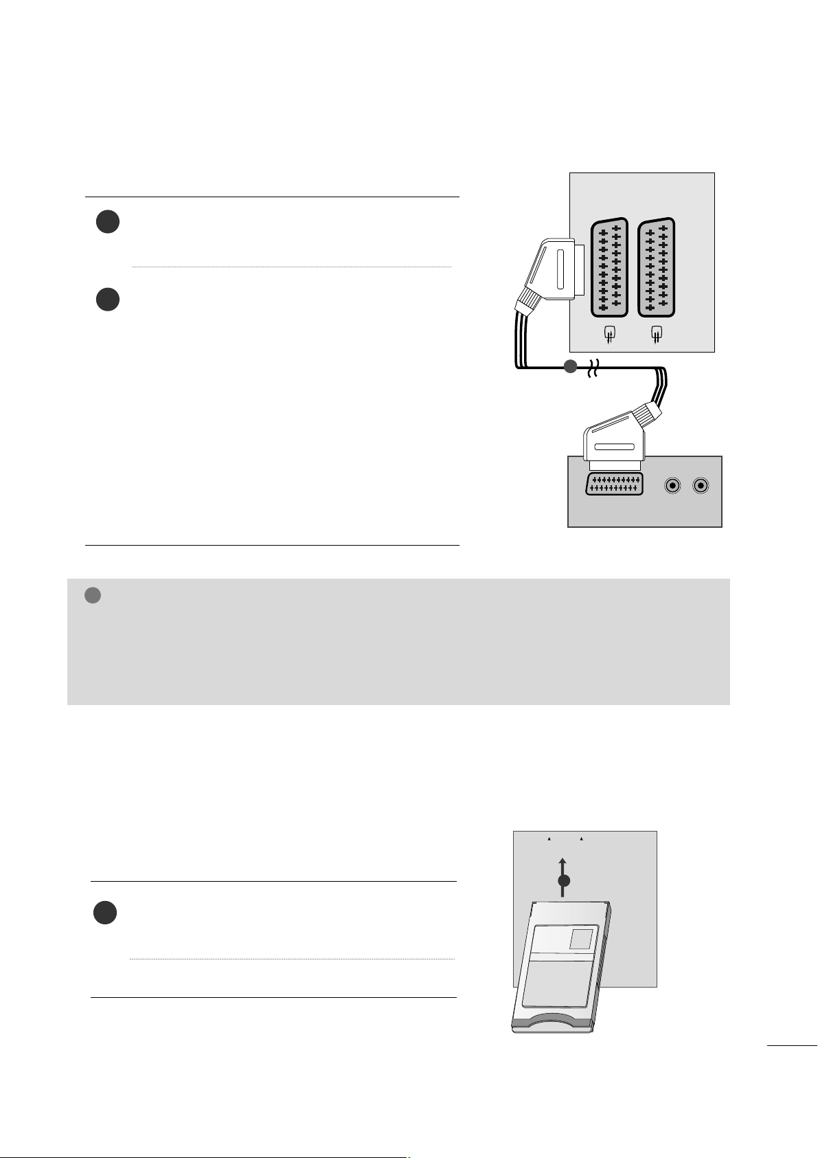
When connecting with a Euro Scart
Connect the Euro scart socket of the DVD to the Euro scart
socket of the set.
Press the
IINN PPUU TT
button to select
AV 1.
If connected to
AA VV22
Euro scart socket, select
AA VV22
input
source.
Press the
PPLLAA YY
button on the DVD.
The DVD playback picture appears on the screen.
2
3
1
1
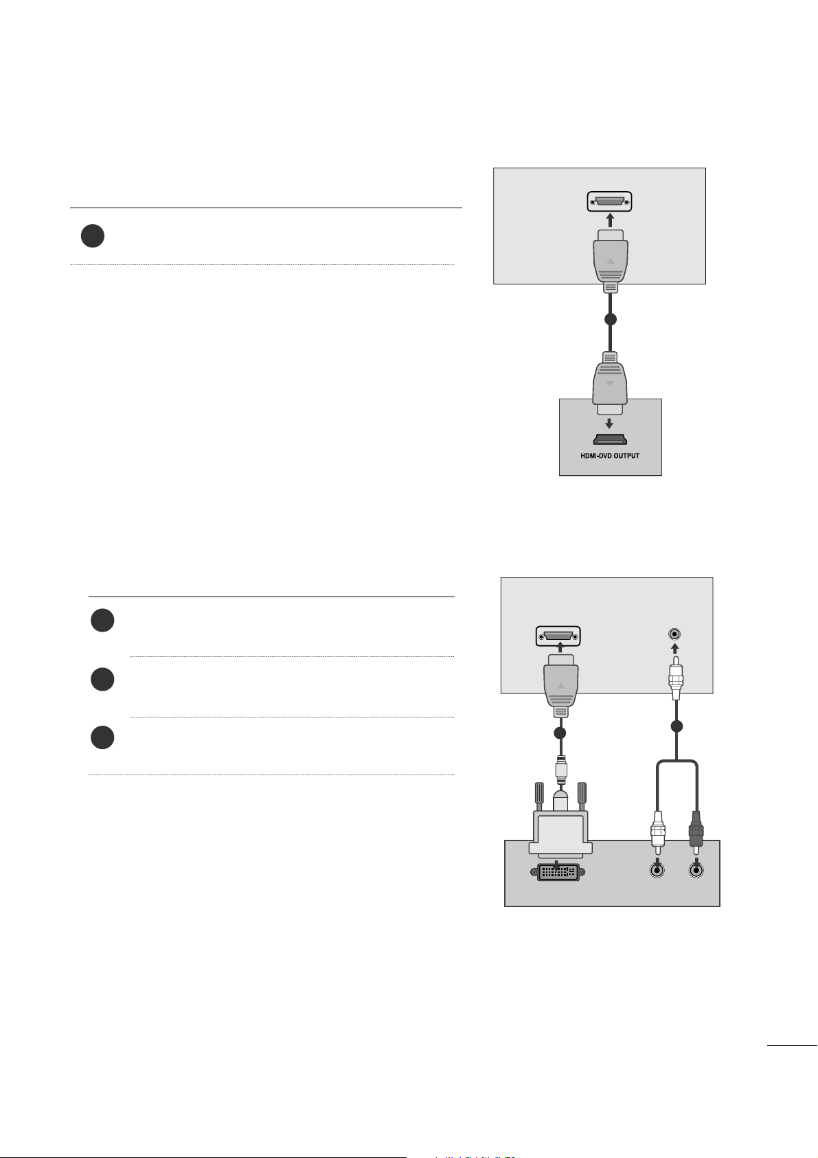
When connecting HDMI cable
Connect the HDMI output of the DVD to the
HH DDMMII//DD VVII IINN
jack on the set.
1
1
GG
Set can receive the video and audio signal simultaneously by using a HDMI cable.
GG
If the DVD player does not support Auto HDMI, you need to set the DVD output resolution appropriately.
NOTE
!
NOTE
!
GG
Signal type RGB, i.e. the signals red, green and blue can only be selected for the Euro scart and the AV 1 can be
received. These signals are transmitted, for example, by a paid TV decoder, game machine or photo CD unit, etc.
GG
Please use shielded scart cable.
14
EXTERNAL EQUIPMENT SETUP
VCR SETUP
■
To avoid picture noise (interference), leave an adequate distance between the VCR and set.
■
Typically a still picture is shown on the VCR. If a user uses 4:3 picture format for a long time, an afterimage
may remain on the sides of the screen.
OUTPUT
SWITCH
ANT IN
R
S-VIDEO VIDEO
ANT OUT
L
ANTENNA IN
Wall Jack
Antenna
1
2
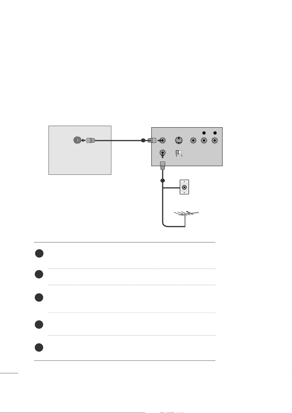
When connecting with an antenna
Connect the RF out socket of the VCR to the aerial socket of the set.
Connect the aerial cable to the RF aerial in socket of the VCR.
Store the VCR channel on a desired programme number using the ‘Manual
programme tuning’ section.
Select the programme number where the VCR channel is stored.
Press the
PPLLAAYY
button on the VCR.
1
2
3
4
5
15
EXTERNAL EQUIPMENT SETUP
(R) AUDIO (L)
AUDIO/
VIDEO
AV 1V 1 AV 2V 2
When connecting with a Euro Scart
Connect the Euro scart socket of the VCR to the Euro
scart socket of the set.
Press the
PPLLAA YY
button on the VCR.
If your VCR outputs an AV switching signal via the Scart
lead, the set will auto switch to
AV 1 mode on start of
playback, but if you want to keep on watching in TV mode,
press the
DD
//
EE
or NUMBER buttons.
If connected to
AA VV22
Euro scart socket, select
AA VV22
input
source.
Otherwise press the
IINN PPUU TT
button on the remote control
handset to select
AV 1 . The VCR playback picture appears
on the screen.
You can also record programmes received by the set on
video tape.
2
1
1
NOTE
!
GG
Signal type RGB, i.e. the signals red, green and blue can only be selected for the Euro scart and the AV 1
can be received. These signals are transmitted, for example, by a paid TV decoder, game machine or photo
CD unit, etc.
GG
Please use shielded scart cable.
Insert the CI Module to
PPCCMM CCIIAA
(Personal Computer
Memory Card International Association)
CCAA RRDD SSLLOOTT
of set as shown.
For further information, see p. 39.
1
INSERTION OF CI MODULE
PCMCIA
CARD SLOT
TVTVTV
-- TToo vvii eeww tt hh ee ssccrr aammbblleedd ((ppaaii dd)) ssee rr vviicceess iinn ddii gg iittaall TTVV
mmooddee..
-- TThhiiss ffeeaattuu rr ee iiss nnoott aavvaaii llaa bbllee iinn aallll ccoo uu nnttrriieess..
1
16
EXTERNAL EQUIPMENT SETUP
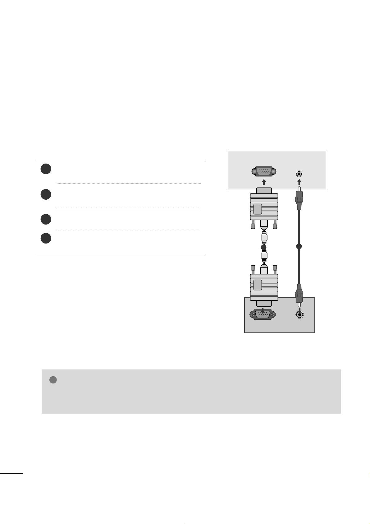
PC SETUP
This product provides Plug and Play capability, meaning that the PC adjusts automatically to the set's settings.
When connecting with a D-sub 15 pin cable
RGB OUTPUT
AUDIO
AUDIO IN
(RGB/DVI)
RGB (PC) IN
1
2
4
Connect the signal cable from the monitor output socket of
the PERSONAL COMPUTER to the PC input socket of the set.
Connect the audio cable from the PC to the
AAUUDDIIOO IINN
((RRGGBB//DD VVII))
sockets of the set.
Press the INPUT button to select RGB.
Switch on the PC, and the PC screen appears on the set.
The set can be operated as a PC monitor.
2
3
1
NOTE
!
GG
User must use shielded signal interface cables (D sub 15 pin cable, DVI cable) with ferrite cores to maintain standard compliance for the product.

17
EXTERNAL EQUIPMENT SETUP
AUDIO
DVI OUTPUT
HDMI/DVI IN
AUDIO IN
(RGB/DVI)
When connecting with a HDMI to DVI cable
Connect the DVI output of the PC to the
HH DDMMII//DD VVII
II NN
jack on the set.
Connect the audio cable from the PC to the
AAUUDDII OO
IINN (( RRGG BB// DDVVII))
sockets of the set.
2
1
1
2
NOTE
!
GG
If the set is cold, there may be a small “flicker”
when the set is switched on. This is normal, there
is nothing wrong with the set.
GG
If possible, use the 1680x1050 @ 60 Hz video
mode to obtain the best image quality for your
LCD monitor. If used with other resolutions, some
scaled or processed pictures may appear on the
screen. The set has been preadjusted to the mode
1680x1050 @ 60 Hz.
GG
Some dot defects may appear on the screen, like
Red, Green or Blue spots. However, this will have
no impact or effect on the monitor performance.
GG
Do not press the LCD screen with your finger for
a long time as this may produce some temporary
distortion effects on the screen.
GG
To enjoy best image quality for your LCD monitor,
please change Input label to ‘PC’
(For further information, see p.41)
GG
Avoid keeping a fixed image on the set’s screen
for prolonged periods of time. The fixed image
may become permanently imprinted on the
screen; use a screen saver when possible.

18
EXTERNAL EQUIPMENT SETUP
When connecting with a HDMI to HDMI cable
Connect the HDMI output of the PC to the
HH DDMM II//DDVVII IINN
jack on the set.
1
HDMI/DVI IN
AV 1 AV 2
1
NOTE
!
GG
If the set is cold, there may be a small “flicker”
when the set is switched on. This is normal, there
is nothing wrong with the set.
GG
If possible, use the 1680x1050 @ 60 Hz video
mode to obtain the best image quality for your
LCD monitor. If used with other resolutions, some
scaled or processed pictures may appear on the
screen. The set has been preadjusted to the mode
1680x1050 @ 60 Hz.
GG
Some dot defects may appear on the screen, like
Red, Green or Blue spots. However, this will have
no impact or effect on the monitor performance.
GG
Do not press the LCD screen with your finger for
a long time as this may produce some temporary
distortion effects on the screen.
GG
To enjoy best image quality for your LCD monitor,
please change Input label to ‘PC’
(For further information, see p.41)
GG
Avoid keeping a fixed image on the set’s screen
for prolonged periods of time. The fixed image
may become permanently imprinted on the
screen; use a screen saver when possible.
19
EXTERNAL EQUIPMENT SETUP
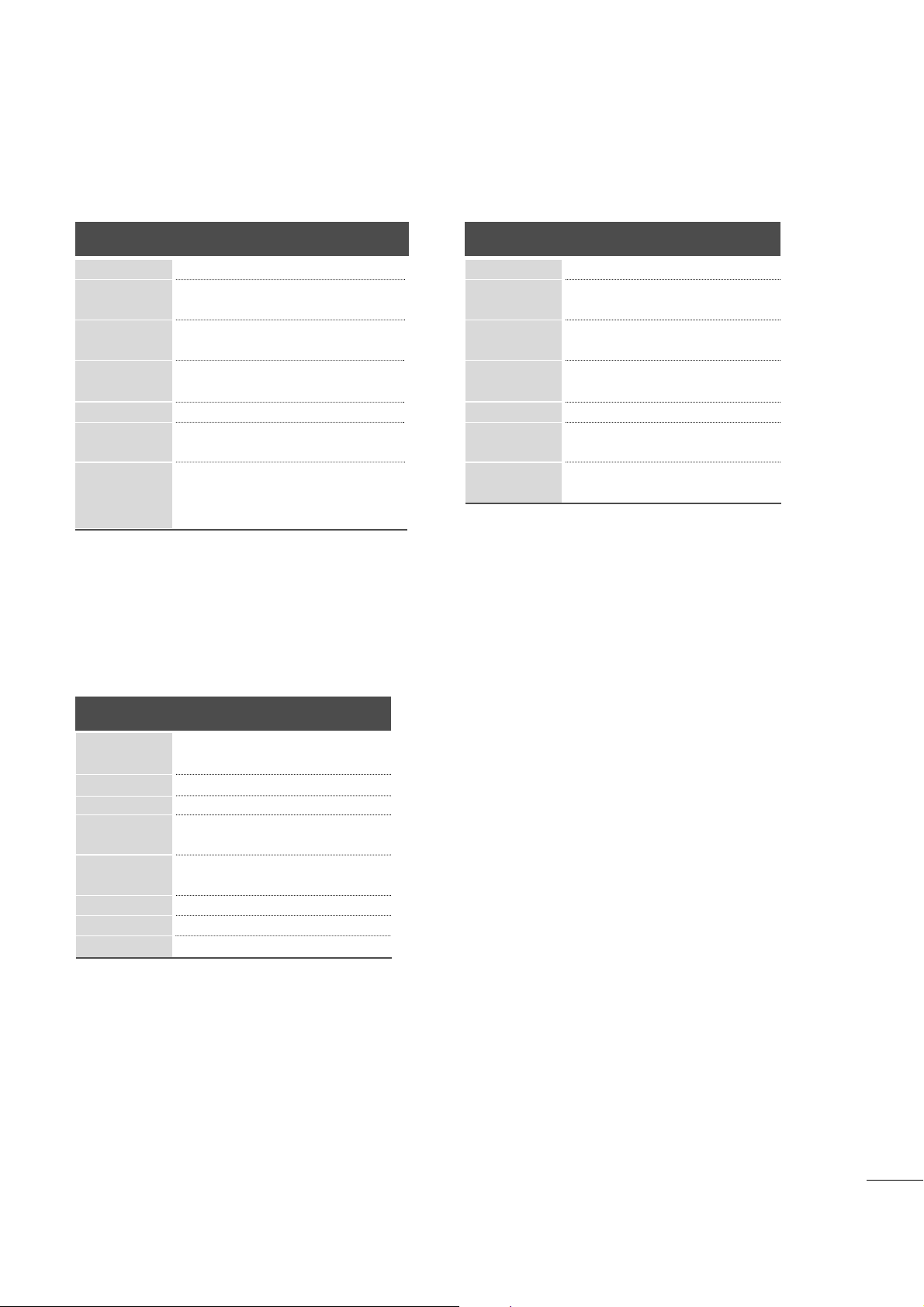
RGB/HDMI[PC] Preset mode
M198WDP
Resolution
640x480
800x600
720x400
10 2 4 x 7 6 8
Horizontal
Frequency(kHz)
Vertical
Frequency(Hz)
70
60
75
60
75
60
75
75
60
75
60
60
75
[[ OOnn ll yy RRGGBB]]
31.468
31.469
37. 500
37. 879
46.875
48.363
60.123
67. 500
63.981
79.976
55.5
55.935
70.635
[[ OOnn ll yy RRGGBB]]
128 0x 10 24
115 2 x 8 6 4
HDMI/DVI-DTV supported mode
60
60
50
50
60
60
60
60
50
50
60
31.47
31.5
31.25
37. 5
44.96
45
33.72
33.75
28.125
56.25
67. 5
Resolution
720x480/60p
720x576/50p
1280x720/60p
1280x720/50p
Horizontal
Frequency(kHz)
Vertical
Frequency(Hz)
1920x1080/60i
1920x1080/50i
1920x1080/50p
1920 x1080/ 60p
14 4 0 x 9 0 0
M228WDP
Resolution
640x480
800x600
720x400
10 2 4 x 7 6 8
Horizontal
Frequency(kHz)
Vertical
Frequency(Hz)
70
60
75
60
75
60
75
75
60
75
60
60
31.468
31.469
37. 500
37. 879
46.875
48.363
60.123
67. 500
63.981
79.976
64.674
65.290
128 0x 10 24
115 2 x 8 6 4
1680x1050
20
EXTERNAL EQUIPMENT SETUP
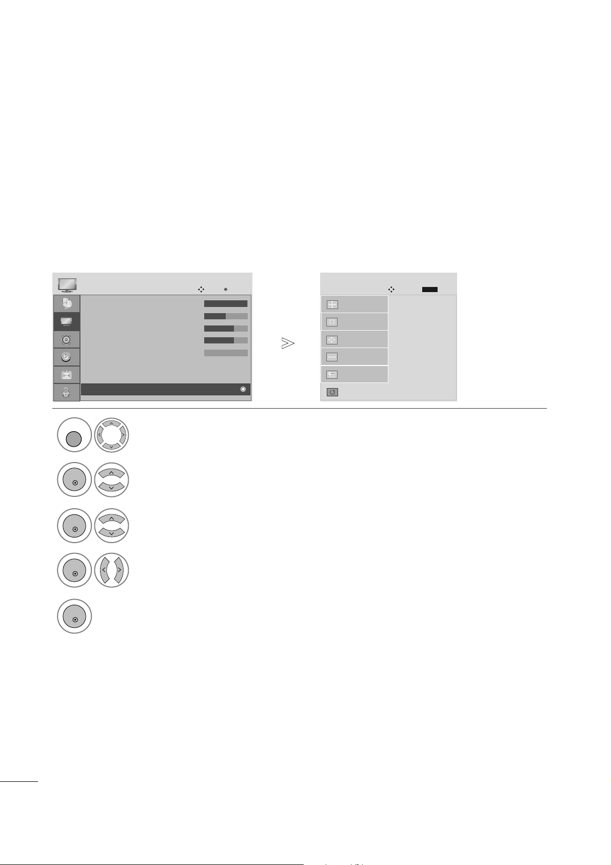
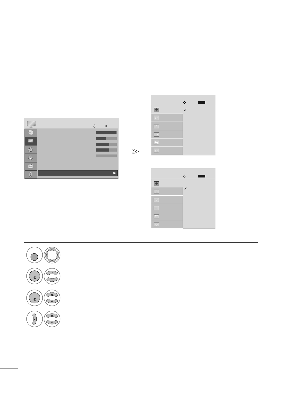
Screen Setup for PC mode
Returns Position, Size and Phase to the default factory settings.
This function works in the following mode: RGB[PC].
Screen Reset
1
Select PICTURE.
2
Select SCREEN.
3
Select Reset.
5
Run Reset.
• Contrast : 100
• Brightness : 50
• Sharpness : 70
• Colour : 70
• Tint : 0
• Advanced Control
• Picture Reset
PICTURE
Move
OK
D
Screen
To S e t
Auto Config.
SCREEN
Move
Prev.
BACK
Resolution
Position
Size
Phase
Reset
G
MENU
OK
OK
OK
4
Select Ye s .
OK
• Press the MENU or EXIT button to close the menu window.
• Press the BACK button to move to the previous menu screen.

21
EXTERNAL EQUIPMENT SETUP
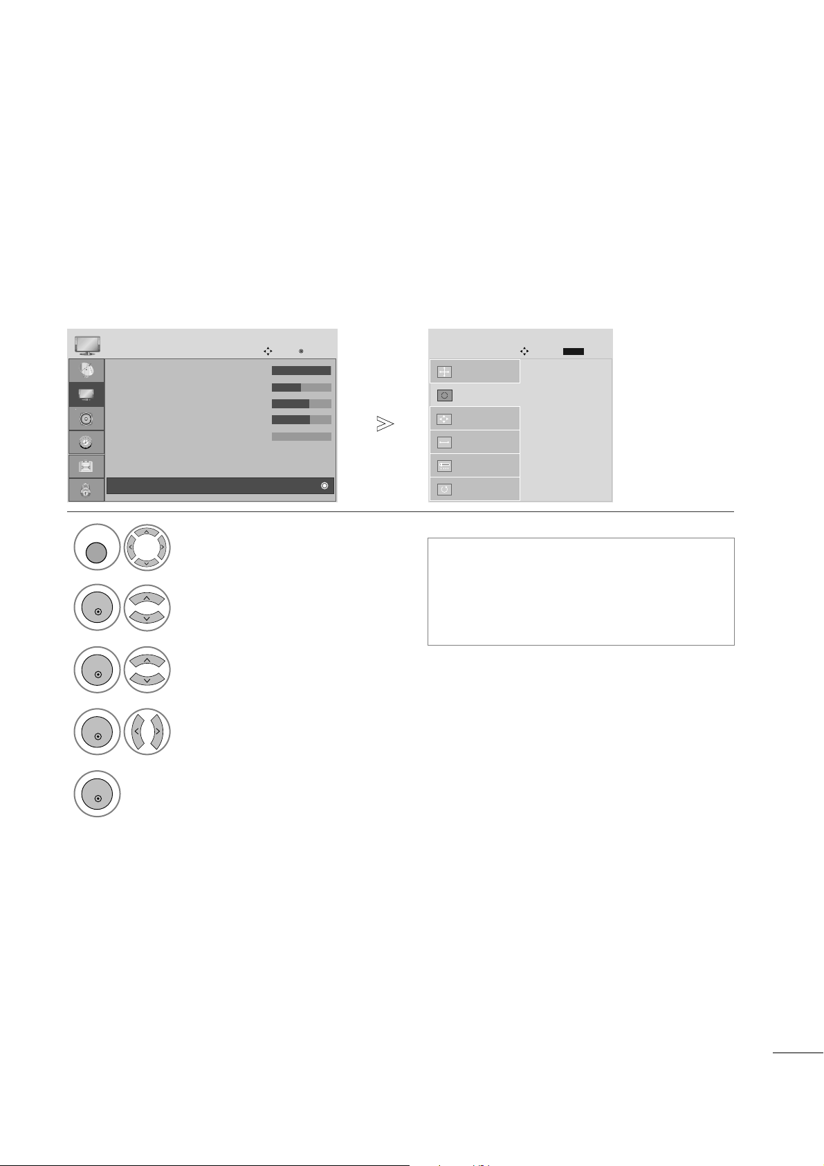
If the picture is not clear after auto adjustment and especially if characters are still shaky, adjust the picture phase manually.
This function works in the following mode: RGB[PC].
Adjustment for screen Position, Size, Phase
1
Select PICTURE.
2
Select SCREEN.
3
Select Position, Size or Phase.
4
Make appropriate adjustments.
• Contrast : 100
• Brightness : 50
• Sharpness : 70
• Colour : 70
• Tint : 0
• Advanced Control
• Picture Reset
PICTURE
Move
OK
D
Screen
Auto Config.
SCREEN
Move
Resolution
Position
G
Size
Phase
Reset
GF
D
E
• Press the MENU or EXIT button to close the menu window.
• Press the BACK button to move to the previous menu screen.
Prev.
BACK
MENU
OK
OK
22
EXTERNAL EQUIPMENT SETUP
To view a normal picture, match the resolution of RGB mode and selection of PC mode.
This function works in the following mode: RGB[PC] mode.
Selecting Resolution
1
Select PICTURE.
<M198WDP>
2
Select SCREEN.
3
Select Resolution.
4
Select the desired resolution.
• Contrast : 100
• Brightness : 50
• Sharpness : 70
• Colour : 70
• Tint : 0
• Advanced Control
• Picture Reset
PICTURE
Move
OK
D
Screen
1024 x 768
1280 x 768
1360 x 768
1366 x 768
Auto Config.
SCREEN
Move
Resolution
G
Position
Size
Phase
Reset
MENU
OK
OK
• Press the MENU or EXIT button to close the menu window.
•
Press the BACK button to move to the previous menu screen.
Prev.
BACK
1400 x 1050
1680 x 1050
Auto Config.
SCREEN
Move
Resolution
G
Position
Size
Phase
Reset
Prev.
BACK
<M228WDP>
23
EXTERNAL EQUIPMENT SETUP
1
Automatically adjusts picture position and minimizes image instability. After adjustment, if the image is still
not correct, your set is functioning properly but needs further adjustment.
AAuuttoo ccoo nn ffii gguu rree
This function is for automatic adjustment of the screen position, clock, and phase The displayed image will
be unstable for a few seconds while the auto configuration is in progress.
Auto Configure (RGB [PC] mode only)
• Press the MENU or EXIT button to close the menu window.
• Press the BACK button to move to the previous menu screen.
•
If the position of the image is still not correct,
try Auto adjustment again.
• If picture needs to be adjusted again after Auto
adjustment in RGB (PC), you can adjust the
PPoossii tt iioo nn, SSii zzee
or
PPhhaassee
.
Select PICTURE.
2
Select SCREEN.
3
Select Auto Config.
• Contrast : 100
• Brightness : 50
• Sharpness : 70
• Colour : 70
• Tint : 0
• Advanced Control
• Picture Reset
PICTURE
Move
OK
D
Screen
To S e t
Auto Config.
G
SCREEN
Move
Resolution
Position
Size
Phase
Reset
MENU
OK
OK
Prev.
BACK
5
Run Auto Config.
OK
4
Select Ye s .
OK
24
WATCHING TV /PROGRAMME CONTROL
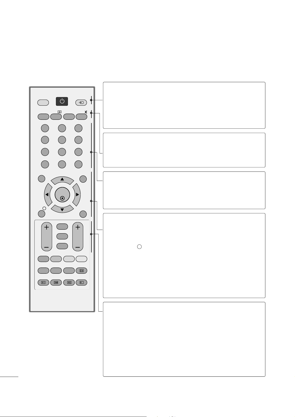
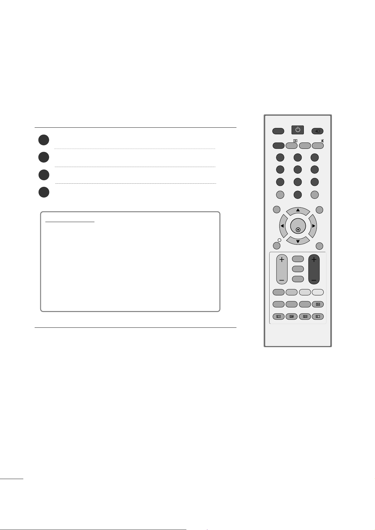
REMOTE CONTROL KEY FUNCTIONS
When using the remote control, aim it at the remote control sensor on the set.
OK
MENU EXIT
GUIDE
RATIO
123
456
789
0
Q.VIEW
LIST
TV INPUT
D/A
POWER
VOL PR
INDEX
SLEEP
HOLD
REVEAL
SUBTITLE
UPDATE
I/II
MUTE
TEXT
BACK
FAV
TIME
INFO
i
TV/RADIO
*
?
POWER
D/A INPUT
INPUT
Switches the set on off.
Selects digital or analogue mode.
Switches the set on.
External input mode rotates in regular sequence.
Switches the set on.
TV/RADIO
I/II
MUTE
Selects Radio or TV channel.
Selects the sound output.
Switches the sound on or off.
0~9 number
button
LIST
Q.VIEW
Selects a programme.
Selects numbered items in a menu.
Displays the programme table.
Returns to the previously viewed programme.
MENU
EXIT
INFO i
GUIDE
THUMBSTICK
(Up/Down/Left
Right)
OK
Selects a menu.
Clears all on-screen displays.
Shows the present screen information.
Shows programme schedule.
Allows you to navigate the on-screen menus and adjust
the system settings to your preference.
Accepts your selection or displays the current mode.
VOLUME UP
/DOWN
BACK
*
FAV
Programme
UP/DOWN
Adjusts the volume.
Allows the user to move back one step in an interactive
application, EPG or other user interaction function.
No function
Displays the selected favourite programme.
Selects a programme.
25
WATCHING TV /PROGRAMME CONTROL
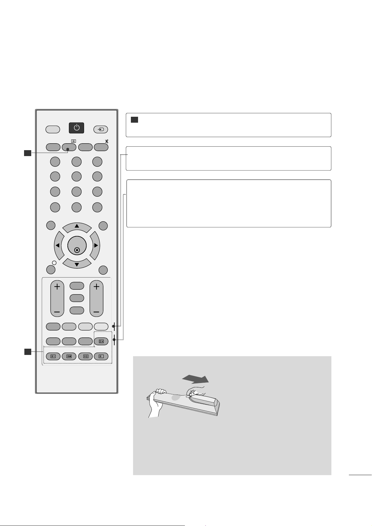
Installing Batteries
■
Open the battery compartment cover on the back and install the
batteries matching correct polarity (+ with +, - with -).
■
Install two 1.5V AAA batteries. Don’t mix old or used batteries with
new ones.
■
Close cover.
OK
MENU EXIT
GUIDE
RATIO
123
456
789
0
Q.VIEW
LIST
TV INPUT
D/A
POWER
VOL PR
INDEX
SLEEP
HOLD
REVEAL
SUBTITLE
UPDATE
I/II
MUTE
TEXT
BACK
FAV
TIME
INFO
i
TV/RADIO
*
?
Coloured
buttons
These buttons are used for teletext (only
TTEE LLEE TTEEXX TT
models) or
PPrrooggrr aammmmee ee ddiitt
.
TELETEXT
BUTTONS
These buttons are used for teletext.
For further details, see the ‘Teletext’ section.
1
1
1
RATIO
SLEEP
SUBTITLE
Selects your desired picture format.
Sets the sleep timer.
Recalls your preferred subtitle in digital mode.
26
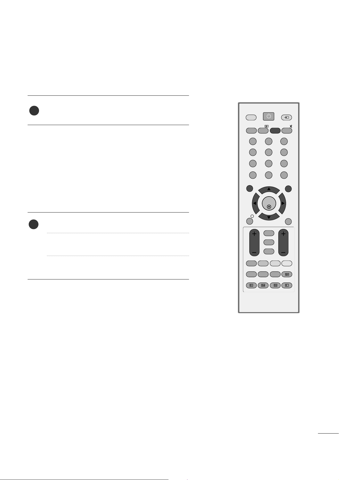
First, connect power cord correctly.
Turn on power by pressing the power button on the product.
Press the TV button on the remote control.
Set the channel by using the PR+ / - buttons or number
buttons on the remote control.
2
1
OK
MENU EXIT
GUIDE
RATIO
123
456
789
0
Q.VIEW
LIST
TV INPUT
D/A
POWER
VOL PR
INDEX
SLEEP
HOLD
REVEAL
SUBTITLE
UPDATE
I/II
MUTE
TEXT
BACK
FAV
TIME
INFO
i
TV/RADIO
*
?
TURNING ON THE TV
Initializing setup
Note:
a. It will automatically disappear after approx. 40 seconds
unless a button is pressed.
b. Press the
BB AA CCKK
button to change current OSD into
previous OSD.
If the OSD (On Screen Display) is displayed on the screen
as figure after turning on the set, you can adjust the
Language, Country, Time Zone, Auto programme tuning.
- If your TV is turned on, you will be able to use its features.
WATCHING TV /PROGRAMME CONTROL
4
3
27
WATCHING TV /PROGRAMME CONTROL
PROGRAMME SELECTION
Press the
PPRR ++ or--
or NUMBER buttons to select a pro-
gramme number.
1
VOLUME ADJUSTMENT
Press the VOL
++ or--
button to adjust the volume.
If you want to switch the sound off, press the MUTE
button.
You can cancel this function by pressing the MUTE,
VOL
++ or--
, or I/II button.
OK
MENU EXIT
GUIDE
RATIO
123
456
789
0
Q.VIEW
LIST
TV INPUT
D/A
POWER
VOL PR
INDEX
SLEEP
HOLD
REVEAL
SUBTITLE
UPDATE
I/II
MUTE
TEXT
BACK
FAV
TIME
INFO
i
TV/RADIO
*
?
1
28
WATCHING TV /PROGRAMME CONTROL
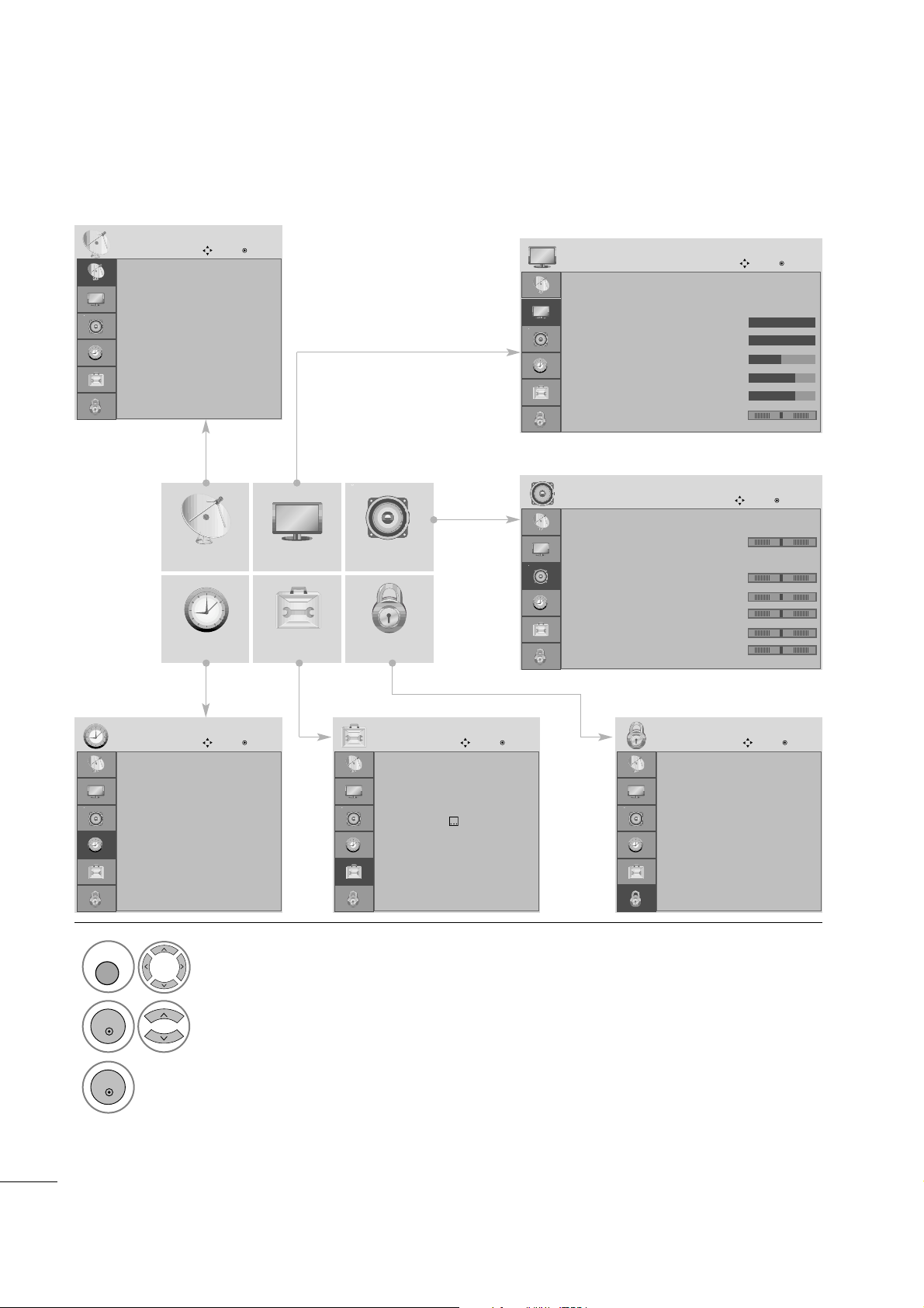
ON SCREEN MENUS SELECTION AND ADJUSTMENT
Your set's OSD (On Screen Display)may differ slightly from what is shown in this manual.
SETUP AUDIO
TIME OPTION LOCK
PICTURE
Auto tuning
Manual tuning
Programme Edit
Booster : On
Software Update : On
Diagnostics
CI Information
SETUP
Move
OK
Aspect Ratio : 16:9
Picture Mode : Vivid
• Backlight 100
• Contrast 100
• Brightness 50
• Sharpness 70
• Colour 70
• Tint 0
PICTURE
Move
OK
E
Auto Volume : Off
Balance 0
Sound Mode : Standard
• 120Hz 0
• 200Hz 0
• 500Hz 0
• 1.2KHz 0
• 3KHz 0
AUDIO
Move
OK
E
Clock
Off Time : Off
On Time : Off
Sleep Timer : Off
Auto Sleep : Off
Time Zone : Canary GMT
TIME
Move
OK
Lock System : Off
Set Password
Block Programme
Parental Guidance : Off
LOCK
Move
OK
Menu Language : English
Audio Language : English
Subtitle Language : English
Hard of Hearing
()
: Off
Country : UK
Input Label
Key Lock : Off
Set ID : 1
OPTION
Move
OK
E
1
Display each menu.
2
Select a menu item.
3
Move to the pop up menu.
LR
-+
-+
-+
-+
-+
RG
MENU
OK
OK
• Press the MENU or EXIT button to close the menu window.
• Press the BACK button to move to the previous menu screen.
 Loading...