

Page 1

ENGLISH
OWNER’S MANUAL
LED LCD MONITOR TV
Please read this manual carefully before operating
your set and retain it for future reference.
LED LCD MONITOR TV MODELS
M2080D
M2280D
M2380D
M2780D
M2380DF
M2780DF
www.lg.com
Page 2

CONTENTS
PREPARATION
FRONT PANEL INFORMATION ..............................4
BACK PANEL INFORMATION .................................5
CONTENTS
STAND INSTALLATION
M2080D/M2280D/M2380D/M2780D .......6
M2380DF/M2780DF .......................................... 7
DETACHING THE STAND
M2080D/M2280D/M2380D/M2780D .......8
M2380DF/M2780DF ..........................................9
DETACHING THE STAND BODY (Only M2080D/
M2280D/M2380D/M2780D) .............................. 10
WALL MOUNT: HORIZONTAL INSTALLATION 11
SWIVEL STAND(Only M2780D / M2780DF) ....12
DESKTOP PEDESTAL INSTALLATION ................12
POSITIONING YOUR DISPLAY ..............................13
LOCATION ....................................................................13
KENSINGTON SECURITY SYSTEM ..................... 14
EXTERNAL EQUIPMENT SETUP
WATCHING TV/CHANNEL CONTROL
REMOTE CONTROL KEY FUNCTIONS ............. 33
TURNING ON THE TV ............................................ 35
CHANNEL SELECTION .......................................... 35
VOLUME ADJUSTMENT ........................................ 35
INITIAL SETTING ...................................................... 36
QUICK MENU .............................................................37
ON-SCREEN MENU SELECTION AND
ADJUSTMENT ........................................................... 38
AUTO SCAN (AUTO TUNING) ............................. 39
ADD/DELETE CHANNEL (MANUAL TUNING) ...40
CHANNEL EDITING ...................................................41
CHANNEL LIST ......................................................... 42
FAVORITE CHANNEL SETUP ............................... 43
FAVORITE CHANNEL LIST .................................... 43
BRIEF INFORMATION ............................................. 44
INPUT LIST ................................................................. 45
PICTURE CONTROL
ANTENNA CONNECTION ...................................... 15
HD RECEIVER SETUP
Connecting with a Component Cable ...........16
Connecting a Set-top Box with
an HDMI Cable .....................................................17
Connecting with an HDMI to DVI Cable ...... 18
DVD SETUP
Connecting with a Component Cable ...........19
Connecting with an HDMI Cable ..................20
VCR SETUP
Connecting with an RF Cable ..........................21
Connecting with an RCA Cable .................... 22
DIGITAL AUDIO OUT SETUP ............................... 23
USB SETUP .................................................................24
HEADPHONE SETUP .............................................. 25
OTHER A/V SOURCE SETUP .............................. 26
PC SETUP
Connecting with a D-sub 15-pin Cable ......27
Connecting with an HDMI to DVI Cable ..... 28
Connecting with an HDMI to HDMI Cable ..... 29
BACK COVER WIRE ARRANGEMENT ..............30
SUPPORTED DISPLAY RESOLUTIONS ..............31
ASPECT RATIO SELECTION ................................ 46
PICTURE WIZARD ................................................... 48
ꕫ ENERGY SAVING ............................................... 49
PRESET PICTURE SETTINGS(PICTURE MODE) ...50
MANUAL PICTURE ADJUSTMENT-USER MODE .....51
PICTURE IMPROVEMENT TECHNOLOGY ....... 52
EXPERT PICTURE CONTROL .............................. 53
PICTURE RESET ....................................................... 56
SCREEN SETUP FOR PC MODE
Selecting Resolution ..........................................57
Auto Configure (RGB-PC Mode Only) ........ 58
Adjustment for Screen Position, Size, Phase .... 59
Screen Reset ....................................................... 60
SOUND CONTROL
AUTO VOLUME LEVELER (AUTO VOLUME) ....61
CLEAR VOICE II ........................................................ 62
BALANCE ................................................................... 63
PRESET SOUND SETTINGS
-SOUND MODE ................................................. 64
PRESET SOUND SETTINGS
-USER MODE ..................................................... 65
2
Page 3

Surround X .................................................................. 65
AUDIO RESET ........................................................... 66
TV SPEAKERS ON/OFF SETUP ...........................67
STEREO/SAP BROADCAST SETUP .................. 68
TIME SETTING
CLOCK SETUP
Auto Clock Setup ...............................................69
Manual Clock Setup...........................................70
AUTO ON/OFF TIME SETTING..............................71
SLEEP TIMER SETTING ..........................................72
OPTIONAL SETTINGS
ON-SCREEN MENUS LANGUAGE SELECTION....73
AUDIO LANGUAGE ..................................................74
INPUT LABEL .............................................................75
KEY LOCK ....................................................................76
CAPTION MODE
Analog Broadcasting System Captions .......77
Digital Broadcasting System Captions .........78
Caption Option ....................................................79
POWER INDICATOR ................................................80
DEMO MODE ...............................................................81
USING USB DEVICES
ENTRY MODES ......................................................... 93
PHOTO LIST ............................................................... 95
MUSIC LIST................................................................ 99
MOVIE LIST ...............................................................102
DIVX REGISTRATION CODE ................................107
DEACTIVATION ....................................................... 108
APPENDIX
TROUBLESHOOTING ............................................109
MAINTENANCE.........................................................112
PRODUCT SPECIFICATIONS
<M2080D> ..........................................................113
<M2280D> ..........................................................114
<M2380D/M2380DF> ....................................115
<M2780D/M2780DF> .....................................116
IR CODES ................................................................... 117
EXTERNAL CONTROL THROUGH RS-232C
RS-232C Setup .................................................118
Type of Connector; D-Sub 9-pin Male ........118
Communication Parameters ..........................118
RS-232C Configurations ................................119
Set ID ....................................................................119
CONTENTS
PARENTAL CONTROL/RATINGS
PASSWORD & LOCK SYSTEM SETTINGS
Setting Up Your Password............................... 82
Lock System ........................................................83
Set Password ....................................................... 84
CHANNEL BLOCKING ............................................ 85
MOVIE & TV RATINGS
Movie Rating (MPAA) - For USA/MEXICO ... 86
TV Ratings Children - For USA/MEXICO ...87
TV Ratings General - For USA/MEXICO .... 88
TV Ratings English - For CANADA .............. 89
TV Ratings French - For CANADA ...............90
DOWNLOADABLE RATINGS ..................................91
EXTERNAL INPUT BLOCKING ............................ 92
3
Page 4
PREPARATION
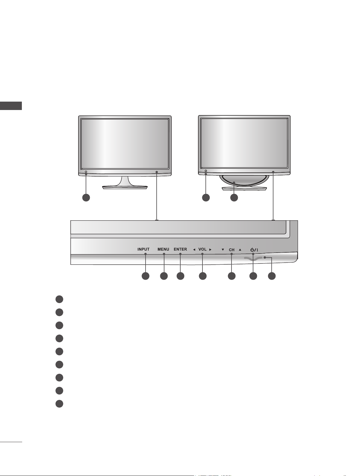
FRONT PANEL INFORMATION
■ This is a simplified representation of the front panel. The image shown may be somewhat different
from your Monitor set.
M2080D / M2280D
PREPARATION
M2380D / M2780D
1 1 2
M2380DF / M2780DF
3 4 5 6 7 8 9
IR RECEIVER (remote control signal receiver)
1
SPEAKER (WOOFER)
2
INPUT BUTTON
3
MENU BUTTON
4
5
ENTER BUTTON
6
VOLUME BUTTON
7
CHANNEL BUTTON
8
POWER BUTTON
9
POWER INDICATOR
Illuminates blue when the set is switched on.
Note: You can adjust the power indicator in the OPTION menu.
4
Page 5
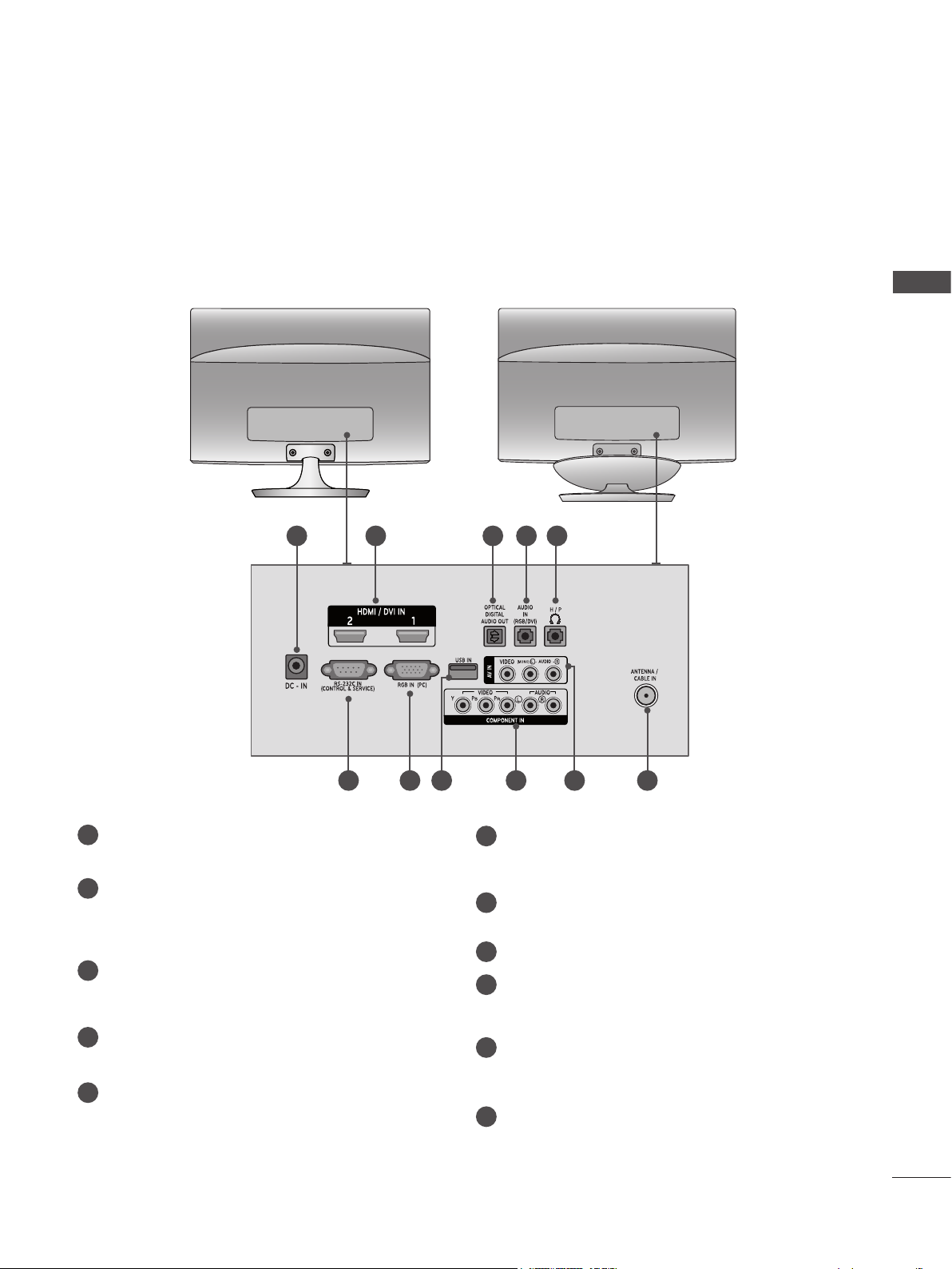
BACK PANEL INFORMATION
■ This is a simplified representation of the front panel. The image shown may be somewhat different
from your Monitor set.
M2080D / M2280D
M2380D / M2780D
M2380DF / M2780DF
PREPARATION
1
1
DC ADAPTER PORT
Connect to the power jack.
HDMI INPUT
2
Connect an HDMI signal to HDMI IN or a DVI
(VIDEO) signal to HDMI IN with a DVI to HDMI
cable.
OPTICAL DIGITAL AUDIO OUT
3
Connect digital audio to various types of equipment with an optical audio cable.
RGB/DVI AUDIO INPUT
4
Connect the audio from a PC.
HEADPHONE SOCKET
5
Plug headphones into the headphone socket.
2 3 4 5
6 7 8 9
10 11
RS-232C IN (CONTROL & SERVICE) PORT
6
Connect to the RS-232C port on a PC.
This port is used for Service or Hotel mode.
RGB INPUT (PC)
7
Connect the output from a PC.
8
USB INPUT
COMPONENT INPUT
9
Connect a component video/audio device to
these jacks.
10
AV(AUDIO/VIDEO) INPUT
Connect audio/video output from an external
device to these jacks.
ANTENNA / CABLE INPUT
11
Connect over-the-air signals to this jack.
5
Page 6
PREPARATION
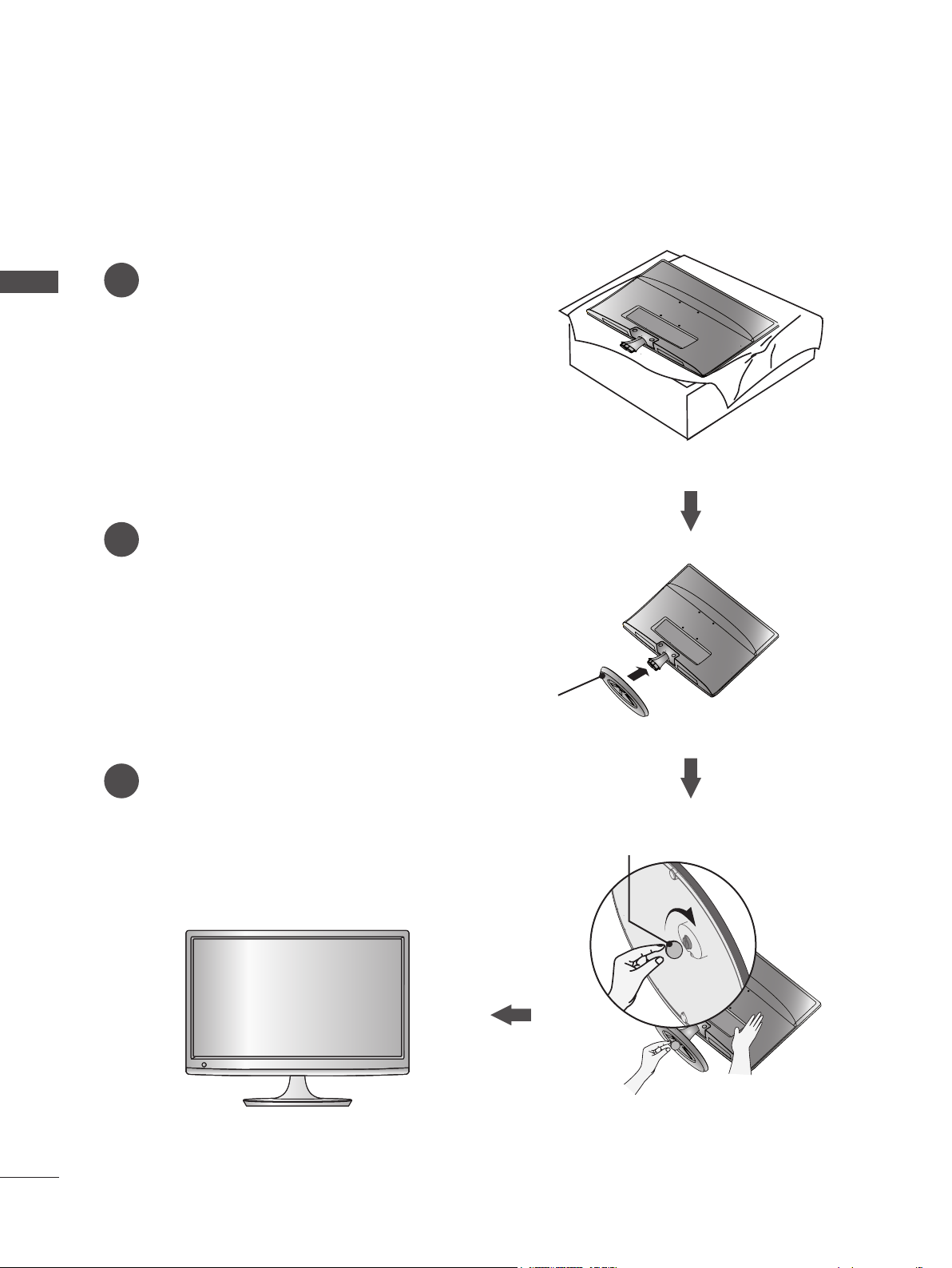
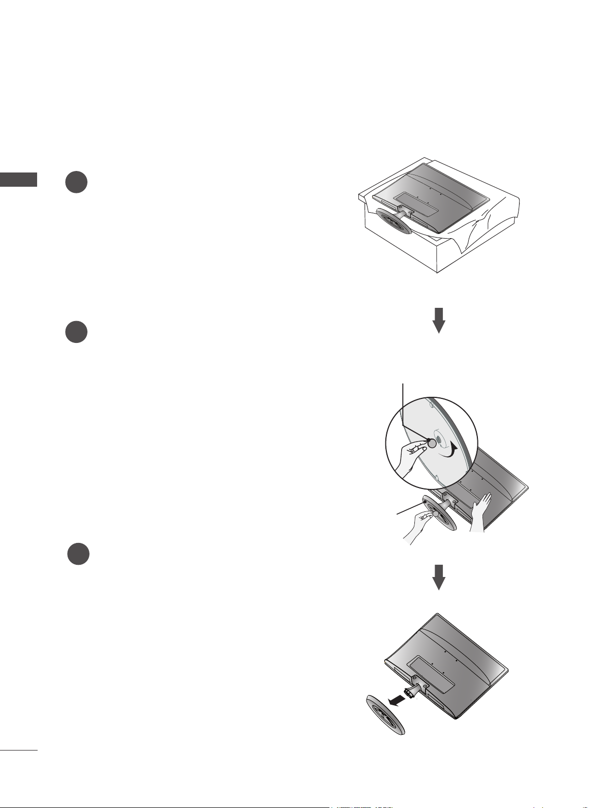
STAND INSTALLATION
■ The image shown may be somewhat different from your Monitor set.
Carefully place the product screen side down on a
1
PREPARATION
cushioned surface that will protect the Monitor set
and its screen from damage.
Insert the Stand Base into the product.
2
M2080D/M2280D/M2380D/M2780D
Use a Coin on the bottom of the stand base
3
and turn the screw clockwise to tighten.
Stand Base
Coin
6
Page 7
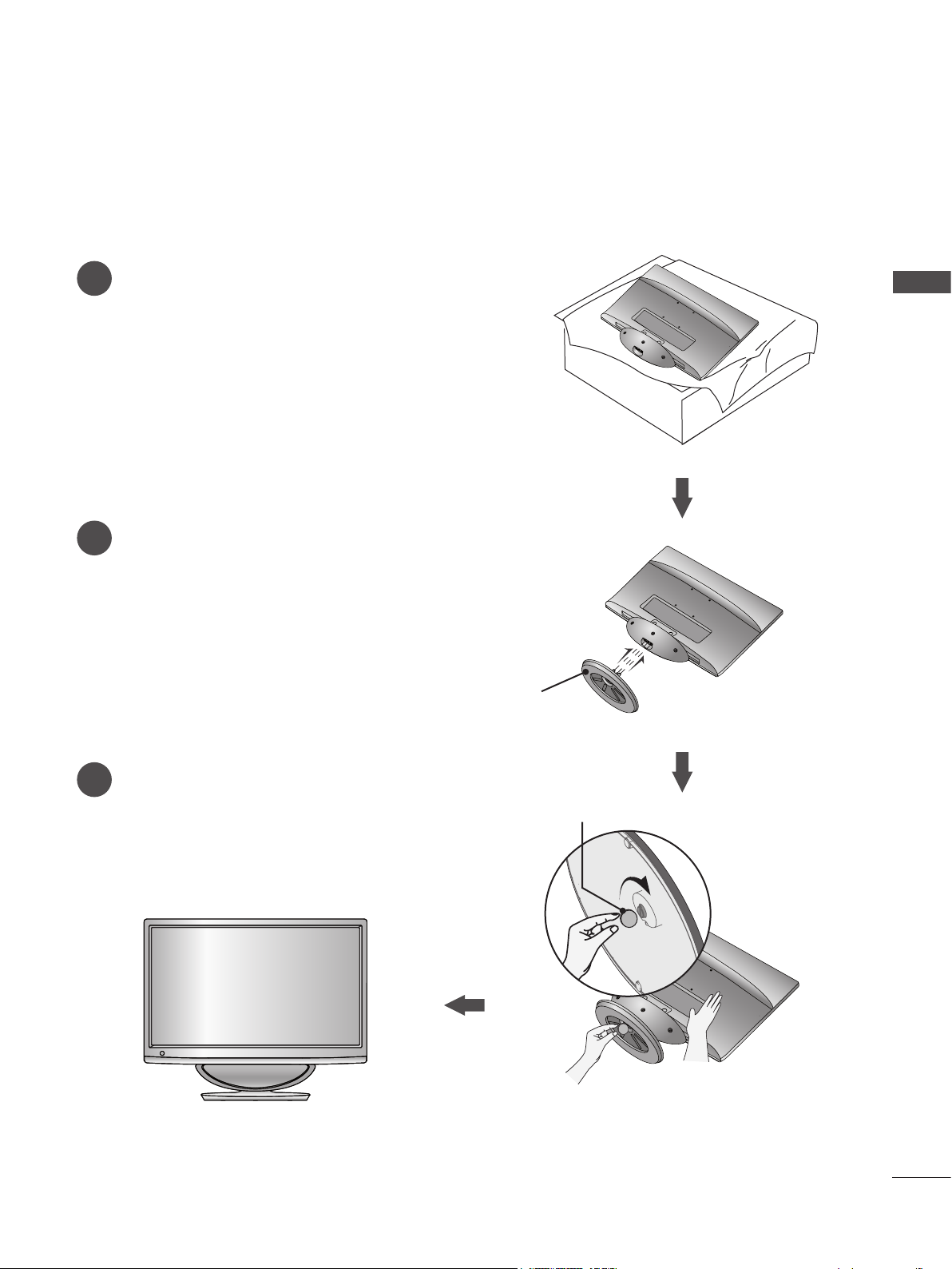
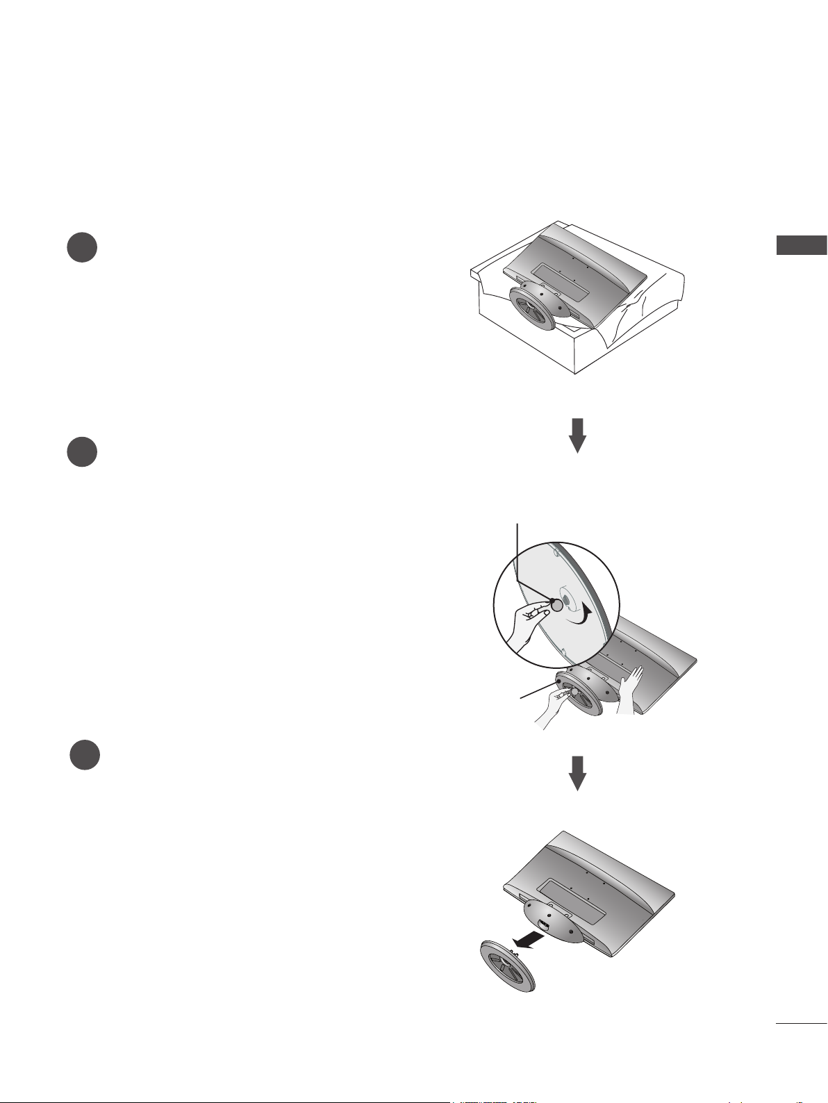
STAND INSTALLATION
■ The image shown may be somewhat different from your Monitor set.
Carefully place the product screen side down on a
1
cushioned surface that will protect the Monitor set
and its screen from damage.
Insert the Stand Base into the product.
2
M2380DF/M2780DF
PREPARATION
Use a Coin on the bottom of the stand base
3
and turn the screw clockwise to tighten.
Stand Base
Coin
7
Page 8
PREPARATION
DETACHING THE STAND
■ The image shown may be somewhat different from your Monitor set.
Place the Monitor set screen side down on a
PREPARATION
1
cushion or soft cloth.
Detach the Stand Base from the set by turning the
2
screw to the left with a Coin.
M2080D/M2280D/M2380D/M2780D
Pull the stand base.
3
Coin
Stand Base
8
Page 9
DETACHING THE STAND
■ The image shown may be somewhat different from your Monitor set.
Place the Monitor set screen side down on a
1
cushion or soft cloth.
Detach the Stand Base from the set by turning the
2
screw to the left with a Coin.
M2380DF/M2780DF
PREPARATION
Coin
Pull the stand base.
3
Stand Base
9
Page 10
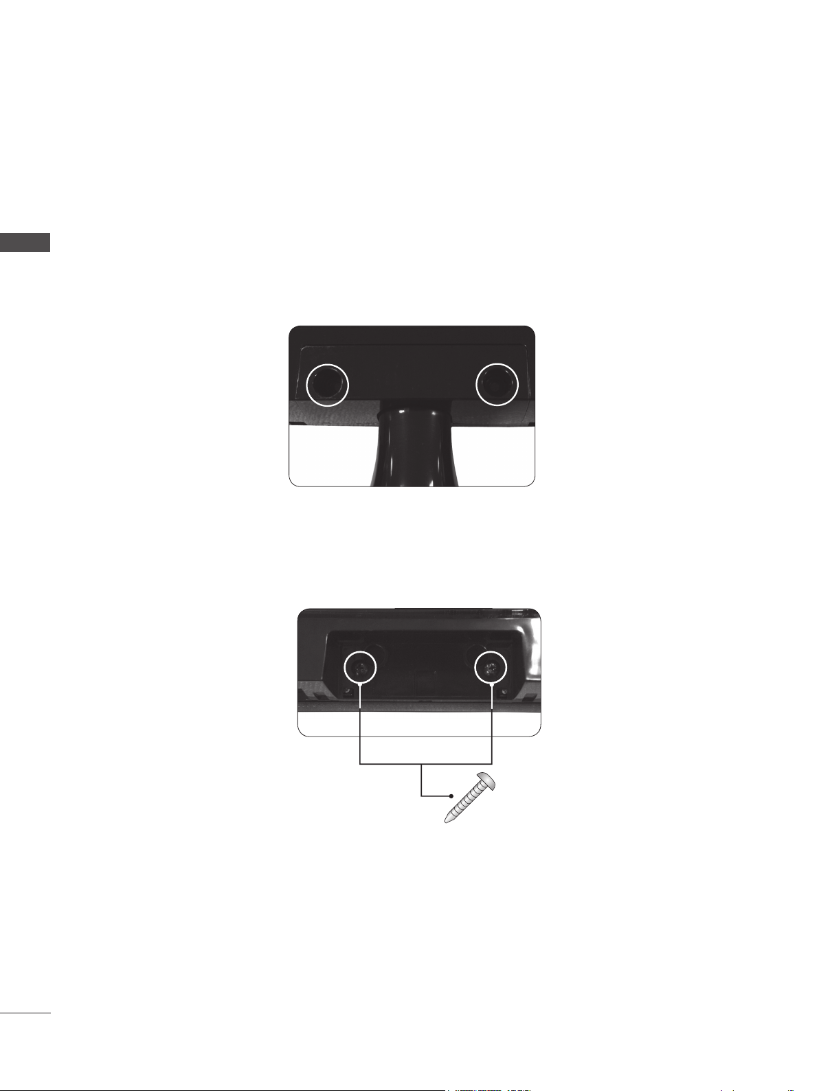
PREPARATION
DETACHING THE STAND BODY (Only M2080D/ M2280D/M2380D/M2780D)
■ When using a VESA mount on the monitor set, you may wish to remove the stand body.
■ The image shown may be somewhat different from your Monitor set.
PREPARATION
1. Remove the screw 2 points.
2. Pull the stand body.
3. Assemble the screw 2 points.
Screw
10
Page 11
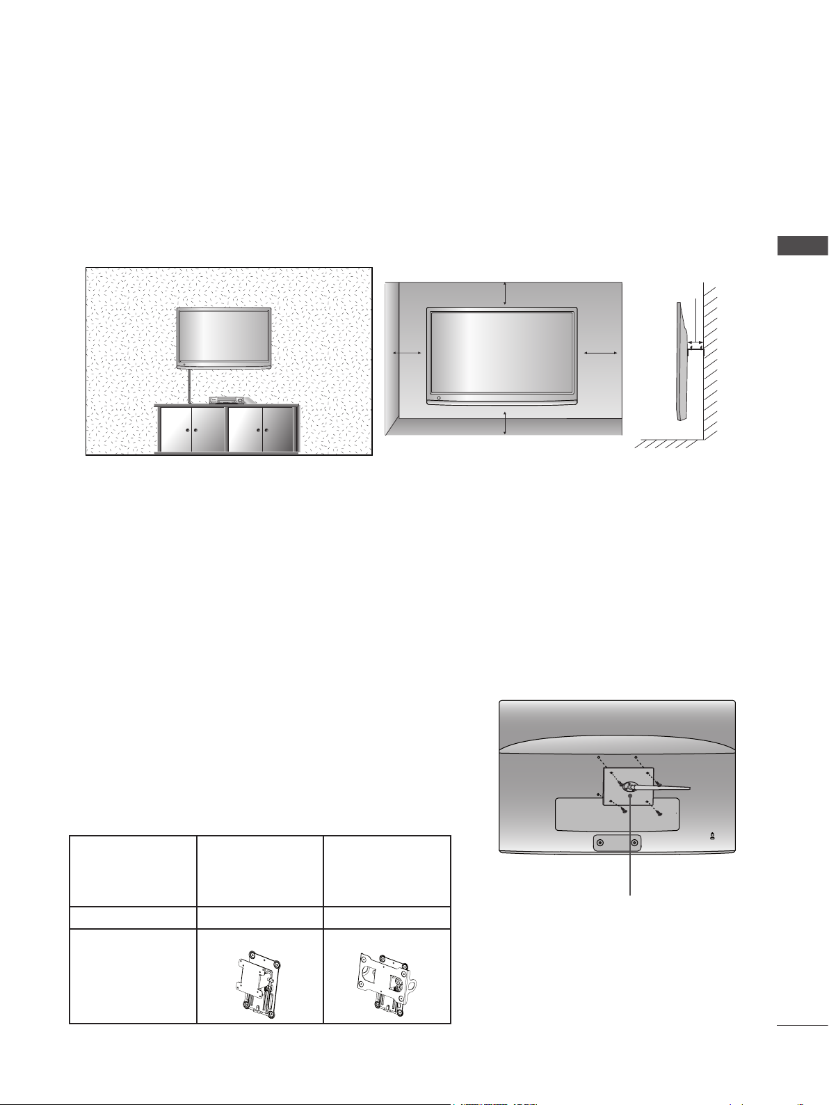
WALL MOUNT: HORIZONTAL INSTALLATION
■ The image shown may be somewhat different from your Monitor set.
For proper ventilation, allow a clearance of 10 cm on each side and from the wall. Detailed installation instructions are available from your dealer. See the optional Tilt Wall Mounting Bracket Installation and Setup Guide.
PREPARATION
10 cm
10 cm
10 cm
10 cm
10 cm
If you intend to mount the Monitor set to a wall, attach the wall mounting interface (optional) to the back of
the Monitor set. When you install the Monitor set using the wall mounting interface (optional), attach it carefully so it will not drop.
1. Be sure to use screws and a wall mount that meet VESA standards.
2. Using screws longer than those recommended might damage the Monitor set.
3. Using screws that do not meet VESA standards might either damage the Monitor set or result in it coming away from the wall. LG is not responsible for any damage resulting from failure to follow these instructions.
4. "VESA compatible" refers to the screw mounting interface dimensions and mounting screw specifications.
5. Please use VESA standards as shown below.
5-1) 784.8 mm (30.9 inch) and under
* Wall Mount Pad Thickness: 2.6 mm
* Screw: Φ 4.0 mm x Pitch 0.7 mm x Length 10 mm
5-2) 787.4 mm (31.0 inch) and above
* Please use a VESA standard wall mount pad and screws.
< Screw Mounting Interface Dimensions >
Model M2080D
M2280D
M2780D
M2780DF
M2380D
M2380DF
VESA ( A x B) 75 x 75 200 x 100
Wall mount
RW120 RW240
bracket(optional)
Wall Mount Pad
11
Page 12
PREPARATION
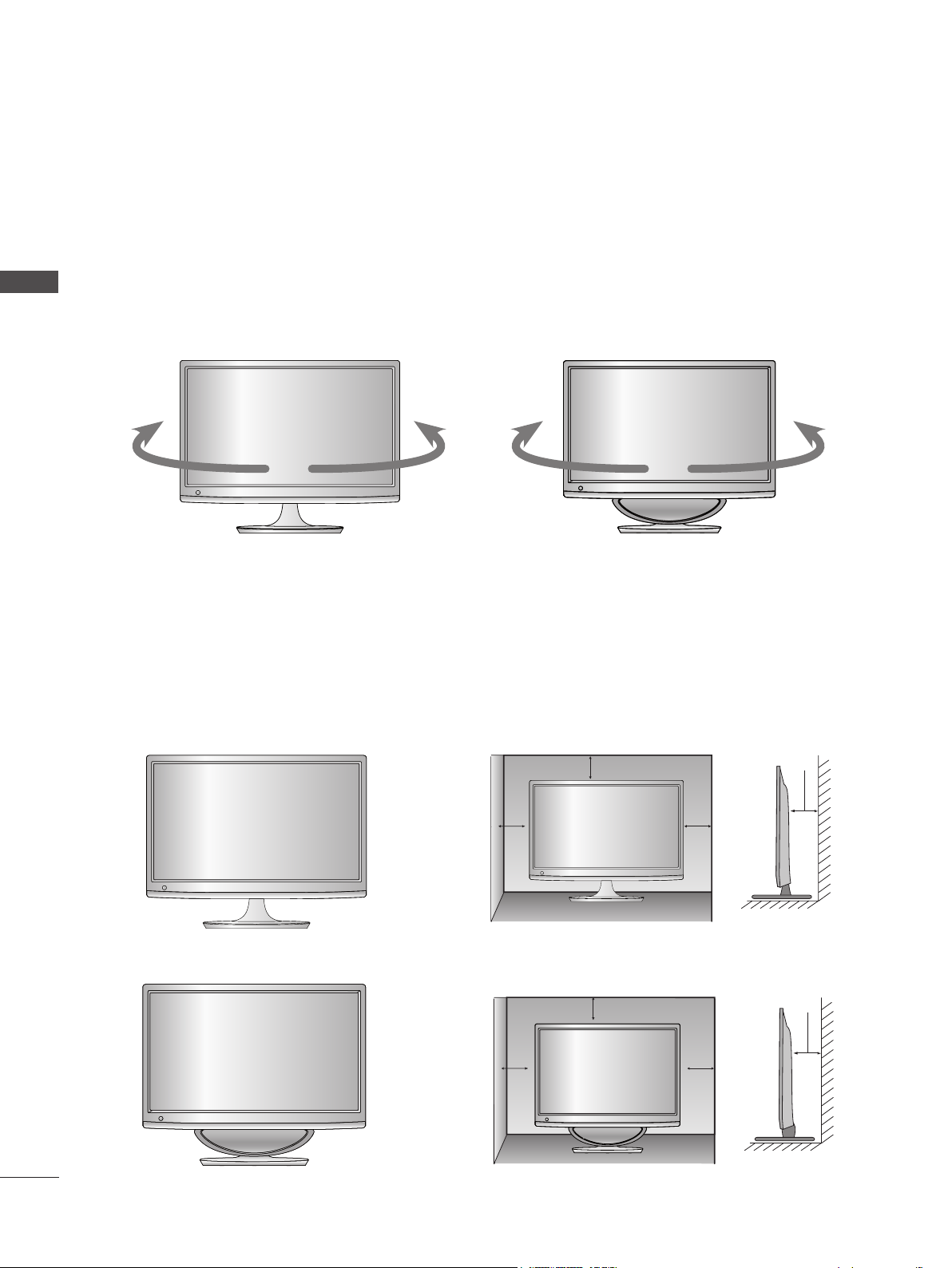
SWIVEL STAND(Only M2780D / M2780DF)
■ The image shown may be somewhat different from your Monitor set.
After installing the set, you can adjust the set manually to the left or right direction by 179 degrees to
suit your viewing position.
PREPARATION
M2780D
M2780DF
DESKTOP PEDESTAL INSTALLATION
■ The image shown may be somewhat different from your Monitor set.
For proper ventilation, allow a clearance of 10 cm on each side and from the wall.
M2080D / M2280D
M2380D / M2780D
10 cm
10 cm
12
M2380DF / M2780DF
10 cm 10 cm
10 cm
10 cm
10 cm
10 cm
Page 13
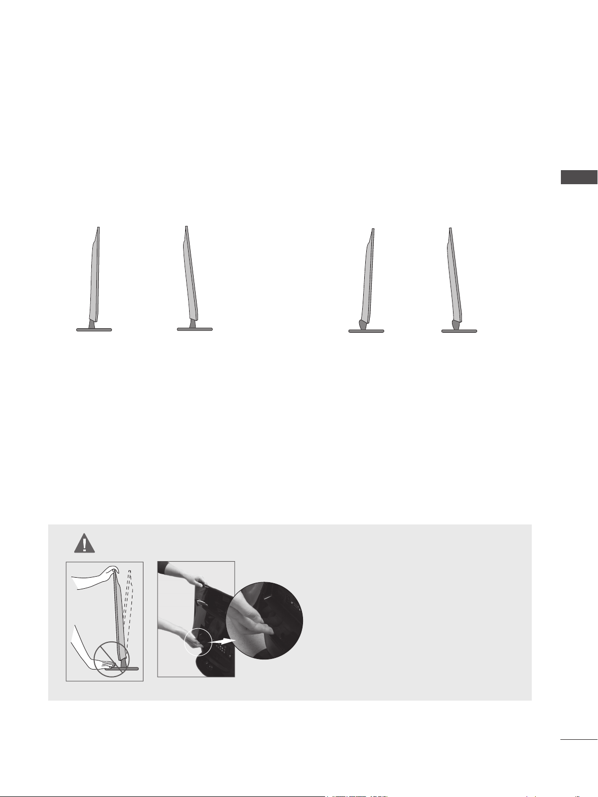
POSITIONING YOUR DISPLAY
■ The image shown may be somewhat different from your set.
Adjust the position of the panel in various ways for maximum comfort.
* Tilt Range
-5° -5°10° 10°
M2080D / M2280D / M2380D / M2780D M2380DF / M2780DF
PREPARATION
LOCATION
Position your set so that no bright light or sunlight falls directly onto the screen. Care should be taken not
to expose the set to any unnecessary vibration, moisture, dust or heat. Also, ensure that the set is placed in
a position to allow a free flow of air. Do not cover the ventilation openings on the back cover.
WARNING
■ When adjusting the angle of the screen, do
not put your finger(s) in between the head of
the monitor and the stand body or woofer.
You can hurt your finger(s).
M2380DF / M2780DF
13
Page 14
PREPARATION
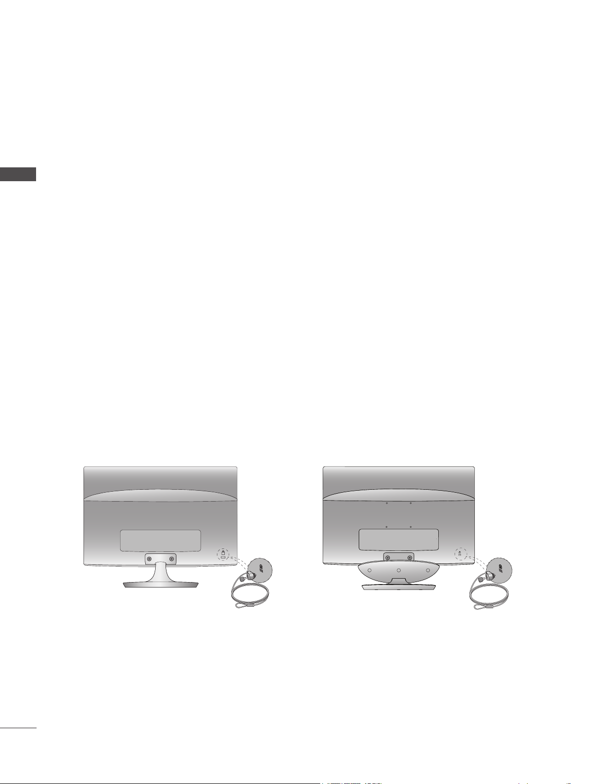
KENSINGTON SECURITY SYSTEM
- The product is equipped with a Kensington Security System connector on the back panel. Connect
the Kensington Security System cable as shown below.
- For detailed installation and use of the Kensington Security System, refer to the user’s guide provided
PREPARATION
with the Kensington Security System.
- For further information, visit http://www.kensington.com. Kensington sells security systems for expensive electronic equipment such as notebook PCs and LCD projectors.
NOTE
- The Kensington Security System is an optional accessory.
NOTES
a. If the product feels cold to the touch, there may be a small “flicker” when it is turned on.
This is normal, there is nothing wrong with product.
b. Some minute dot defects may be visible on the screen, appearing as tiny red, green, or blue spots.
However, they have no adverse effect on the monitor’s performance.
c. Avoid touching the LCD screen or holding your finger(s) against it for long periods of time.
Doing so may produce temporary distortions on the screen.
M2080D / M2280D
M2380D / M2780D M2380DF / M2780DF
14
Page 15
EXTERNAL EQUIPMENT SETUP
■ To prevent damage, do not connect the set to the a power outlet until all connections have been made
between the devices.
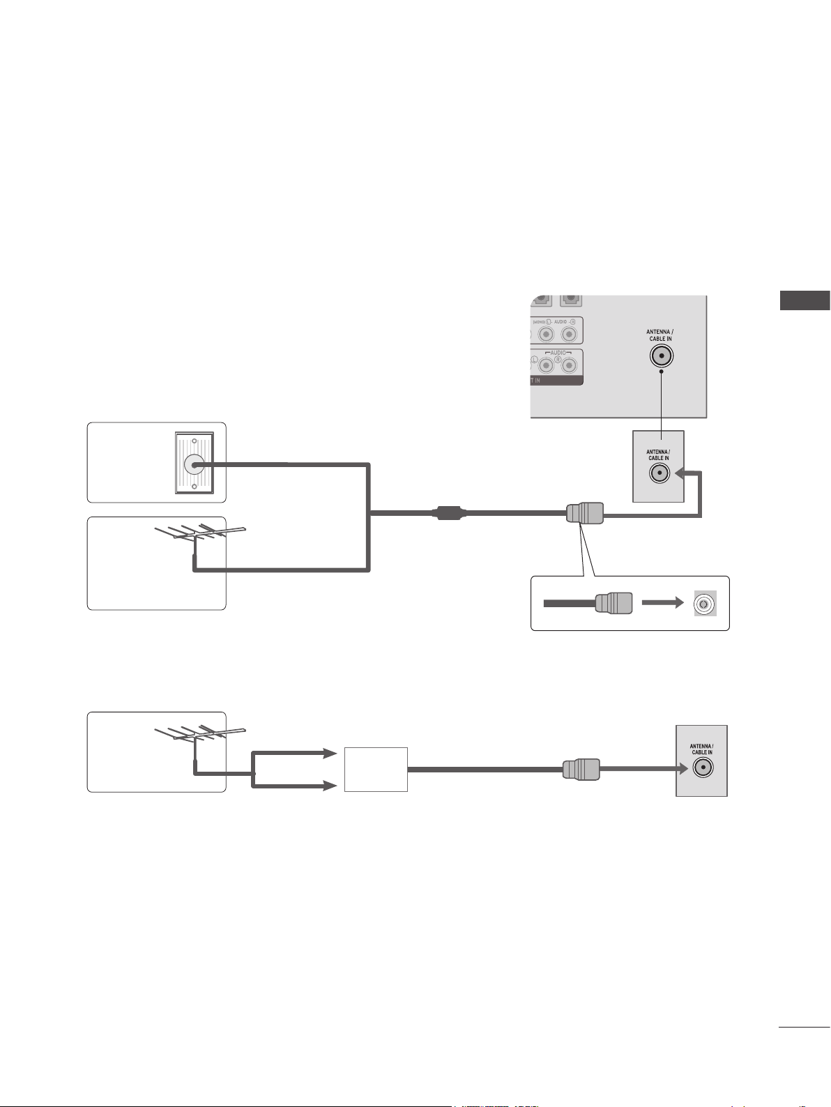
ANTENNA CONNECTION
■ For optimum picture quality, adjust the antenna's direction.
■ An antenna cable and converter are not included with the Monitor set.
Multi-family Dwellings/Apartments
Wall
Antenna
Socket
(Connect to wall antenna socket)
EXTERNAL EQUIPMENT SETUP
RF Coaxial Wire (75 Ω)
Outdoor
Antenna
(VHF, UHF)
Antenna
■ To get better picture quality in poor signal areas, install a signal amplifier to the antenna as shown
above.
■ If the signal needs to be split for two devices, use an antenna signal splitter.
Single-family Dwellings/Houses
(Connect to wall jack for outdoor antenna)
UHF
Signal
Amplifier
VHF
15
Page 16
EXTERNAL EQUIPMENT SETUP
■ To prevent damage, never plug in any power cords until you have finished connecting all equipment.
■ The image shown may be somewhat different from your Monitor set.
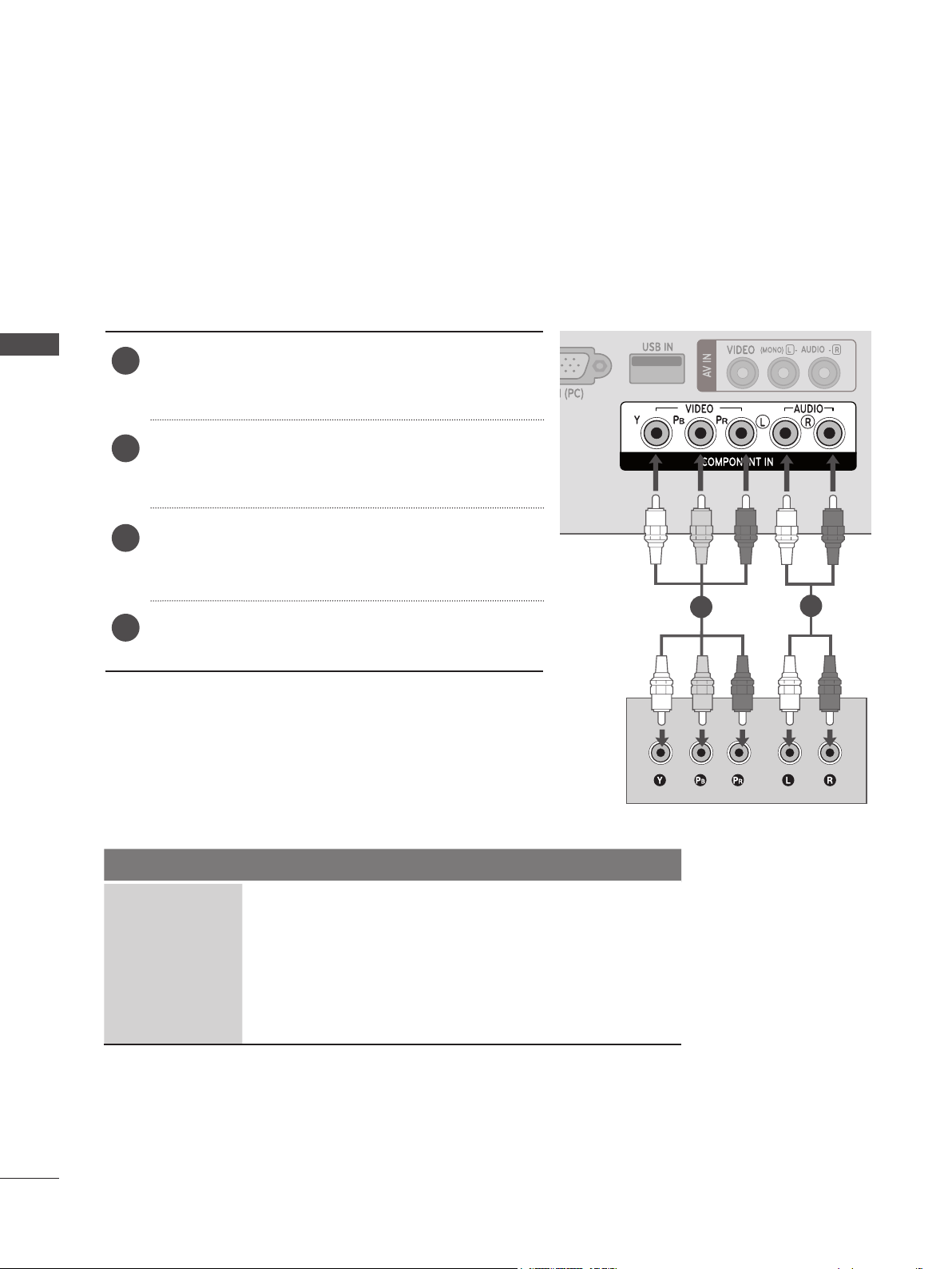
HD RECEIVER SETUP
Connecting with a Component Cable
Connect the video outputs (Y, PB, PR) of the digital
EXTERNAL EQUIPMENT SETUP
1
set-top box to the COMPONENT IN VIDEO jacks on
the Monitor set.
Connect the audio output of the digital set-top box
2
to the COMPONENT IN AUDIO jacks on the
Monitor set.
Turn on the digital set-top box. (Refer to the owner’s
3
manual for the digital set-top box.)
Select COMPONENT input source using the INPUT
4
button on the remote control.
► HDMI Audio Supported formats: Dolby Digital, PCM
DTS Audio format is not supported.
Signal Component HDMI
480i / 576i YES No
480p / 576p YES YES
720p / 1080i YES YES
1080p
YES
(50 Hz / 60Hz only)
(24 Hz / 30 Hz / 50Hz / 60Hz)
YES
1
2
16
Page 17
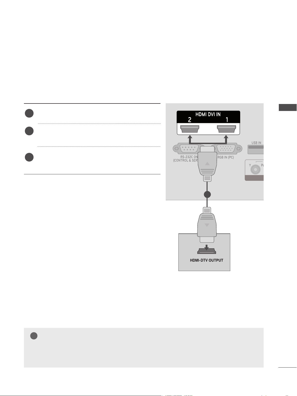
Connecting a Set-top Box with an HDMI Cable
Connect the digital set-top box to the HDMI/DVI IN 1
1
or HDMI/DVI IN 2 jack on the Monitor set.
Turn on the digital set-top box. (Refer to the owner’s
2
manual for the digital set-top box.)
Select HDMI 1 or HDMI 2 input source using the
3
INPUT button on the remote control.
EXTERNAL EQUIPMENT SETUP
1
NOTE
!
►Check that your HDMI cable is a high speed HDMI cable. If the HDMI cables are not high speed,
flickering or no screen display can result.
17
Page 18
EXTERNAL EQUIPMENT SETUP
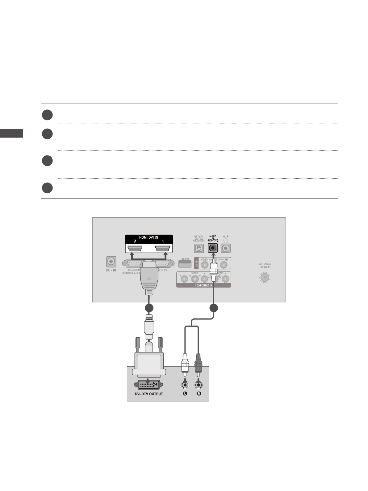
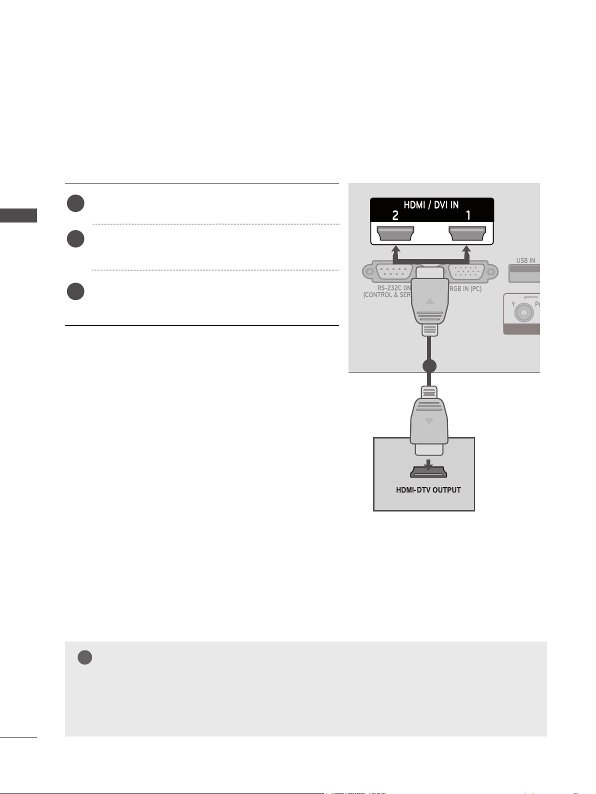
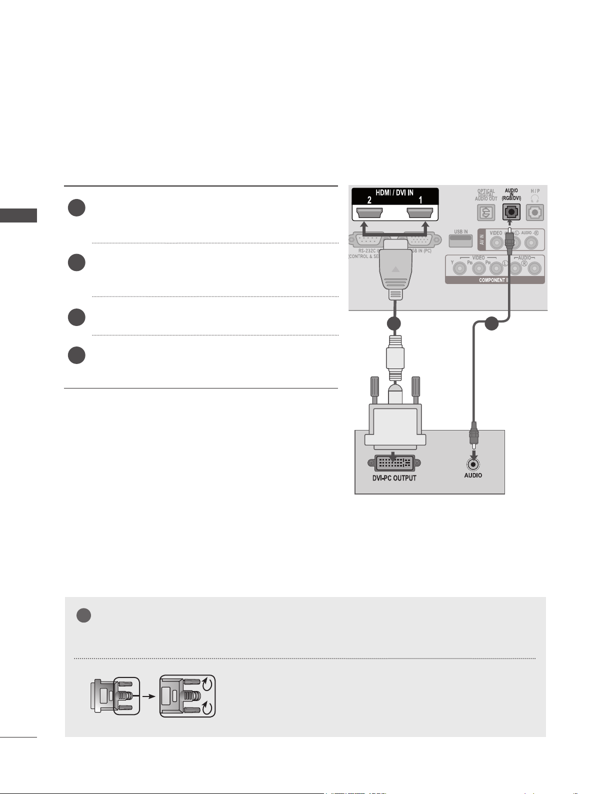
Connecting with an HDMI to DVI Cable
Connect the digital set-top box to the HDMI/DVI IN 1 or HDMI/DVI IN 2 jack on the Monitor set.
1
Connect the audio output of the digital set-top box to the AUDIO IN (RGB/DVI) jack on the
EXTERNAL EQUIPMENT SETUP
2
Monitor set.
Turn on the digital set-top box. (Refer to the owner’s manual for the digital set-top box.)
3
Select HDMI 1 or HDMI 2 using the INPUT on the remote control.
4
18
1 2
Page 19
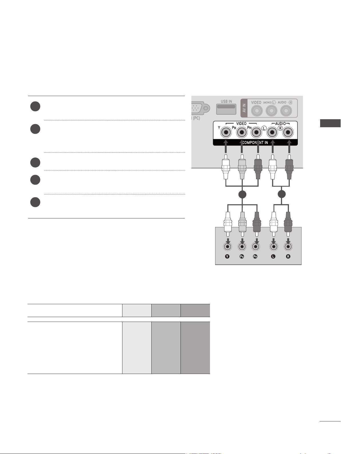
DVD SETUP
Connecting with a Component Cable
Connect the video outputs (Y, PB, PR) of the DVD
1
to the COMPONENT IN VIDEO jacks on the Monitor
set.
2
Connect the audio outputs of the DVD to the
COMPONENT IN AUDIO jacks on the Monitor set.
Turn on the DVD player, insert a DVD.
3
Select Component using the INPUT on the remote
4
control.
1
Refer to the DVD player's manual for operating
5
instructions.
Component Input Ports
For better picture quality, connect a DVD player to the component input ports as shown below.
EXTERNAL EQUIPMENT SETUP
2
Component Ports on the set Y P
Y P
Video output Ports
on the DVD player
Y B-Y R-Y
Y Cb Cr
Y Pb Pr
B
B
P
R
P
R
19
Page 20
EXTERNAL EQUIPMENT SETUP
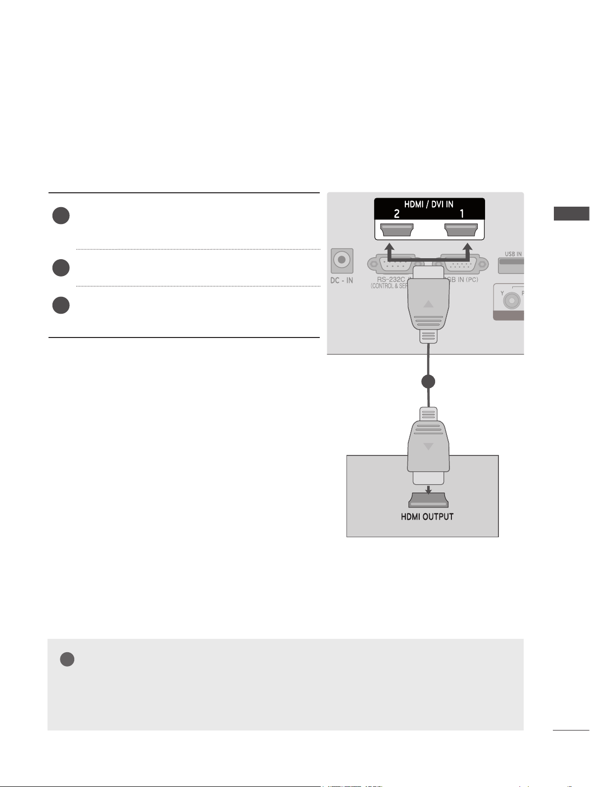
Connecting with an HDMI Cable
Connect the HDMI output of the DVD to the HDMI/
1
DVI IN 1 or HDMI/DVI IN 2 jack on the Monitor set.
EXTERNAL EQUIPMENT SETUP
Select HDMI 1 or HDMI 2 using the INPUT on the
2
remote control.
Refer to the DVD player's manual for operating
3
instructions.
1
20
NOTE
!
►Check that your HDMI cable is a high speed HDMI cable. If the HDMI cables are not high speed,
flickering or no screen display can result.
Page 21
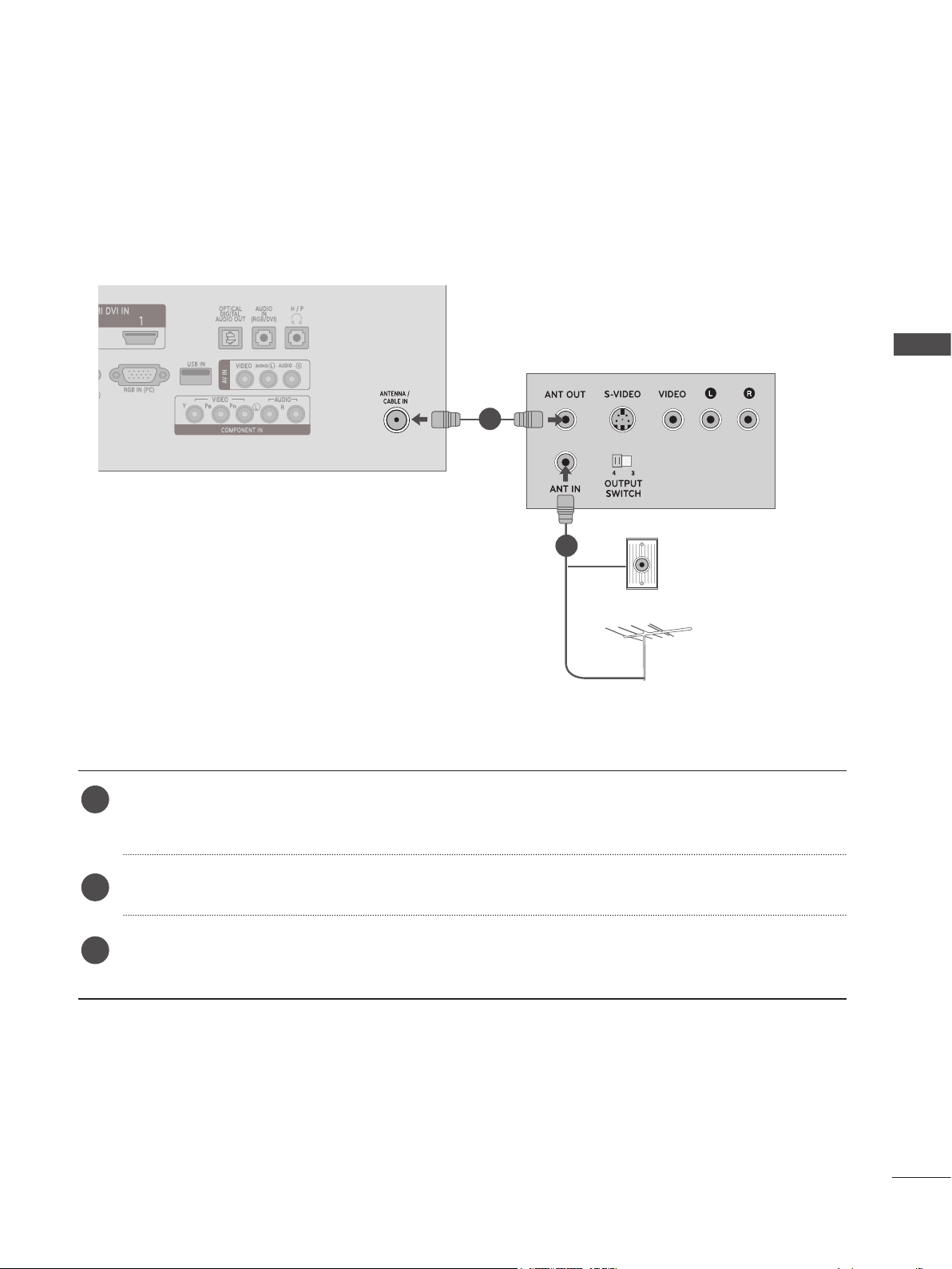
VCR SETUP
■ To avoid picture noise (interference), allow adequate distance between the VCR and set.
Connecting with an RF Cable
1
Wall Jack
2
EXTERNAL EQUIPMENT SETUP
Antenna
Connect the ANT OUT socket of the VCR to the ANTENNA/CABLE IN socket on the Monitor
1
set.
Connect the antenna cable to the ANT IN socket of the VCR.
2
Press PLAY on the VCR and match the appropriate channel between the set and the VCR for
3
viewing.
21
Page 22
EXTERNAL EQUIPMENT SETUP
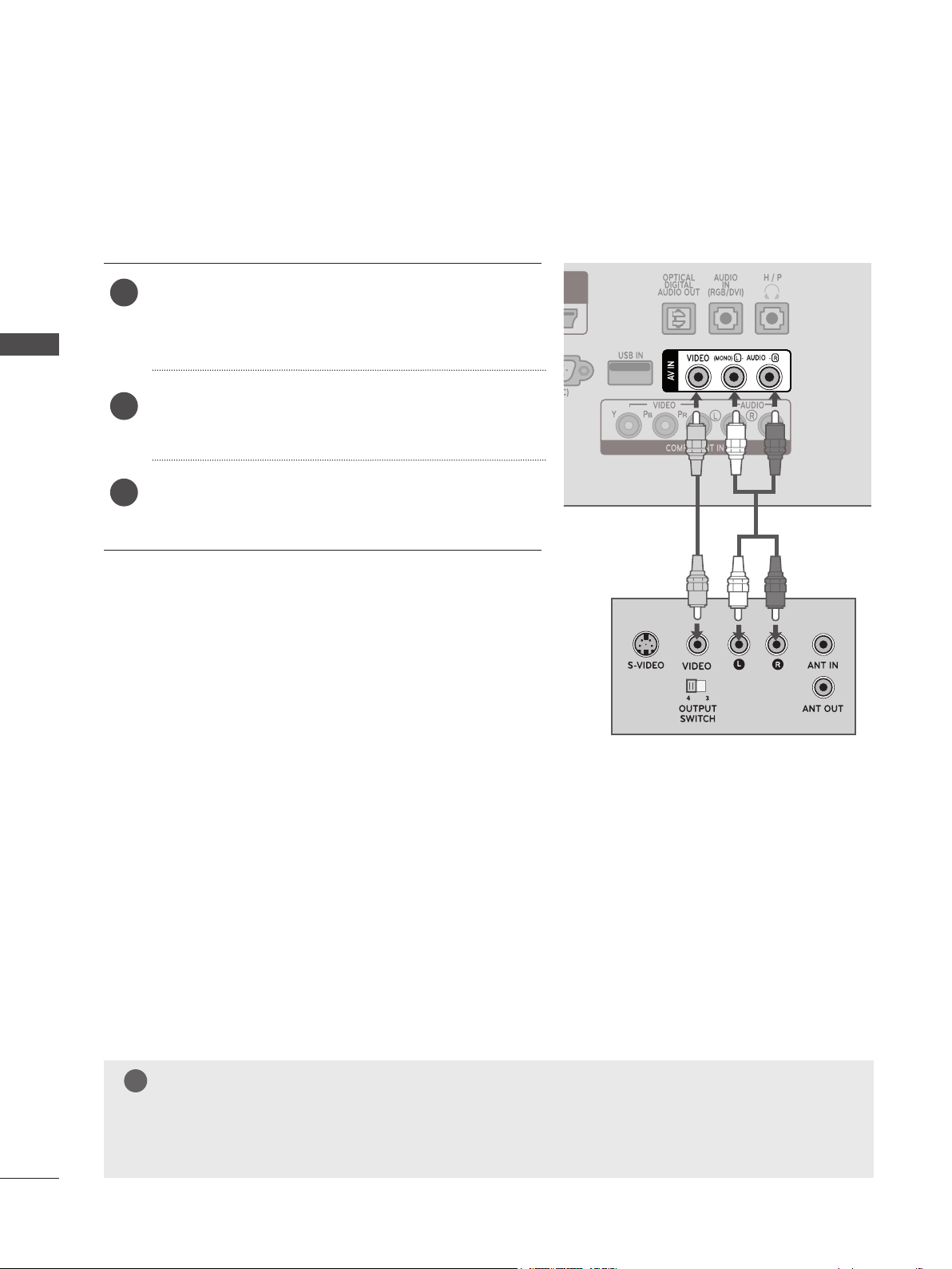
Connecting with an RCA Cable
Connect the AUDIO/VIDEO jacks between set and
1
VCR. Match the jack colors (Video = yellow, Audio
Left = white, and Audio Right = red)
EXTERNAL EQUIPMENT SETUP
Insert a video tape into the VCR and press PLAY.
2
(Refer to the VCR owner’s manual.)
Select AV input source using INPUT on the remote
3
control.
22
NOTE
!
►If you have a mono VCR, connect the audio cable from the VCR to the AUDIO L/MONO jack
of the set.
Page 23
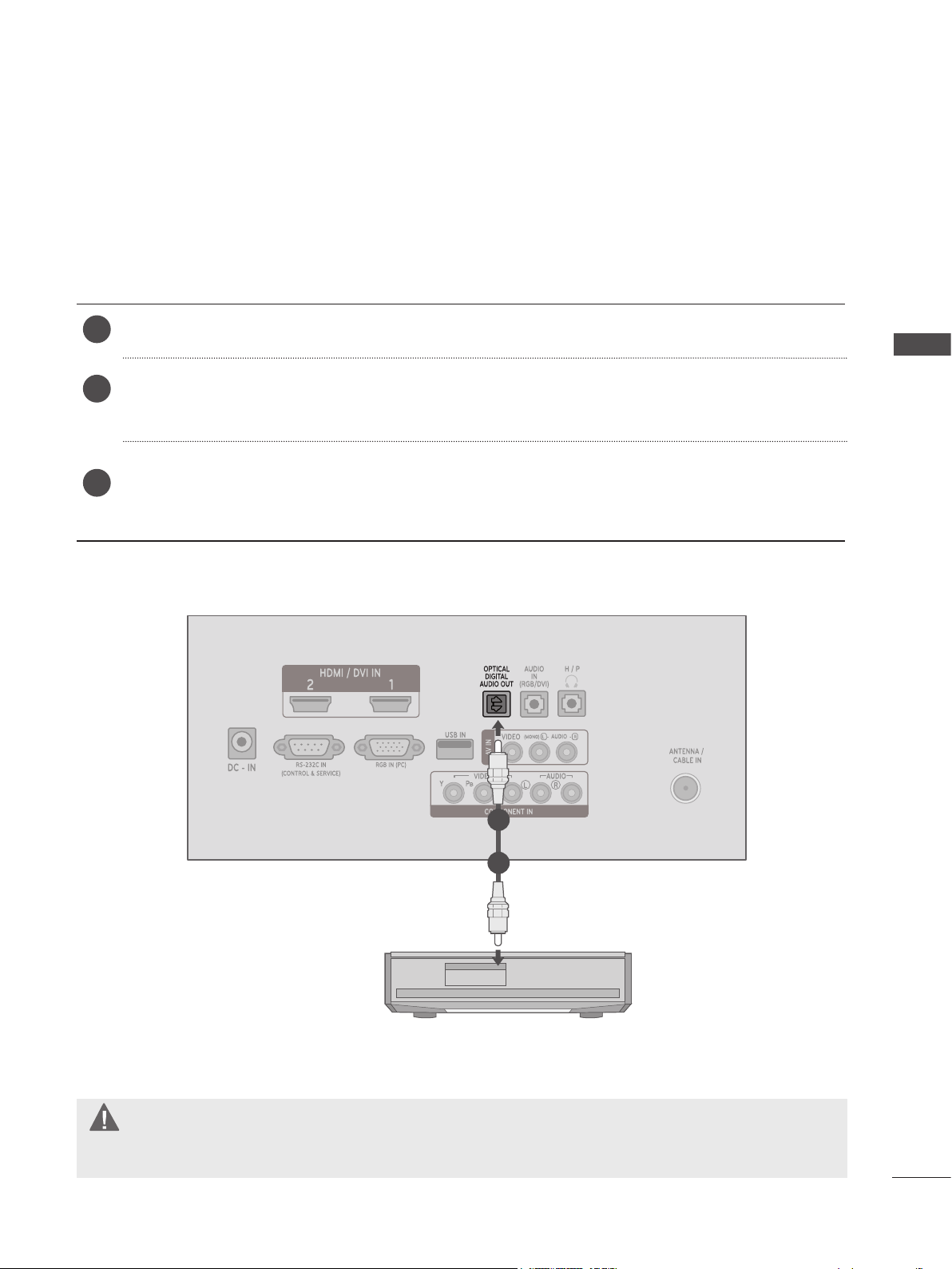
DIGITAL AUDIO OUT SETUP
To send the monitor SET’s audio signal to external audio equipment, use the Digital Audio Output
(Optical) port. If you want to enjoy digital broadcasting through 5.1-channel speakers, connect the
OPTICAL DIGITAL AUDIO OUT terminal on the back of the monitor SET to a home theater (or amp).
Connect one end of an optical cable to the OPTICAL DIGITAL AUDIO OUT port.
1
Connect the other end of the optical cable to the digital audio (Optical) input on the audio
2
equipment.
Set the “TV Speaker option - Off ” in the AUDIO menu. ( P. 67)
3
Refer to the external audio equipment instruction manual for operation.
EXTERNAL EQUIPMENT SETUP
1
2
CAUTION
►Do not look into the optical output port. Looking at the laser beam may damage your vision.
23
Page 24
EXTERNAL EQUIPMENT SETUP
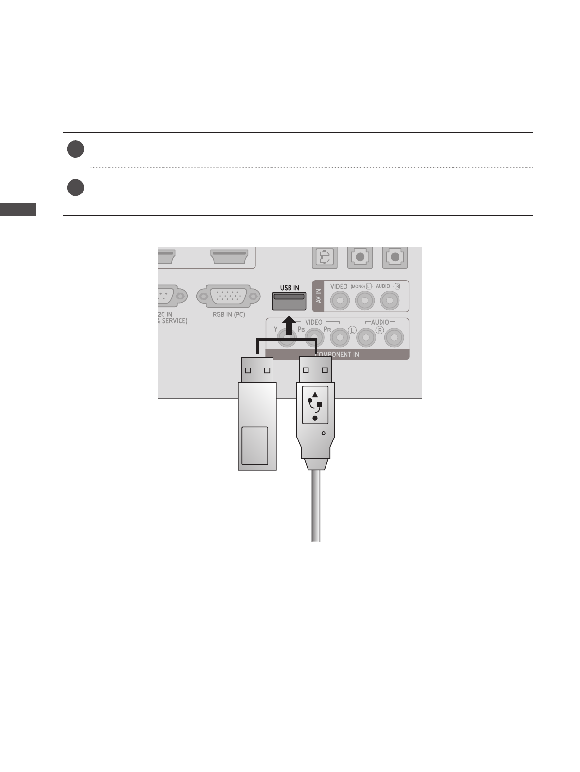
USB SETUP
Connect the USB device to the USB IN jack on the back of the Monitor set.
1
After connecting a USB device to the USB IN jack, you can use various USB functions. ( p.93)
2
EXTERNAL EQUIPMENT SETUP
Memory Stick USB Cable
24
Page 25
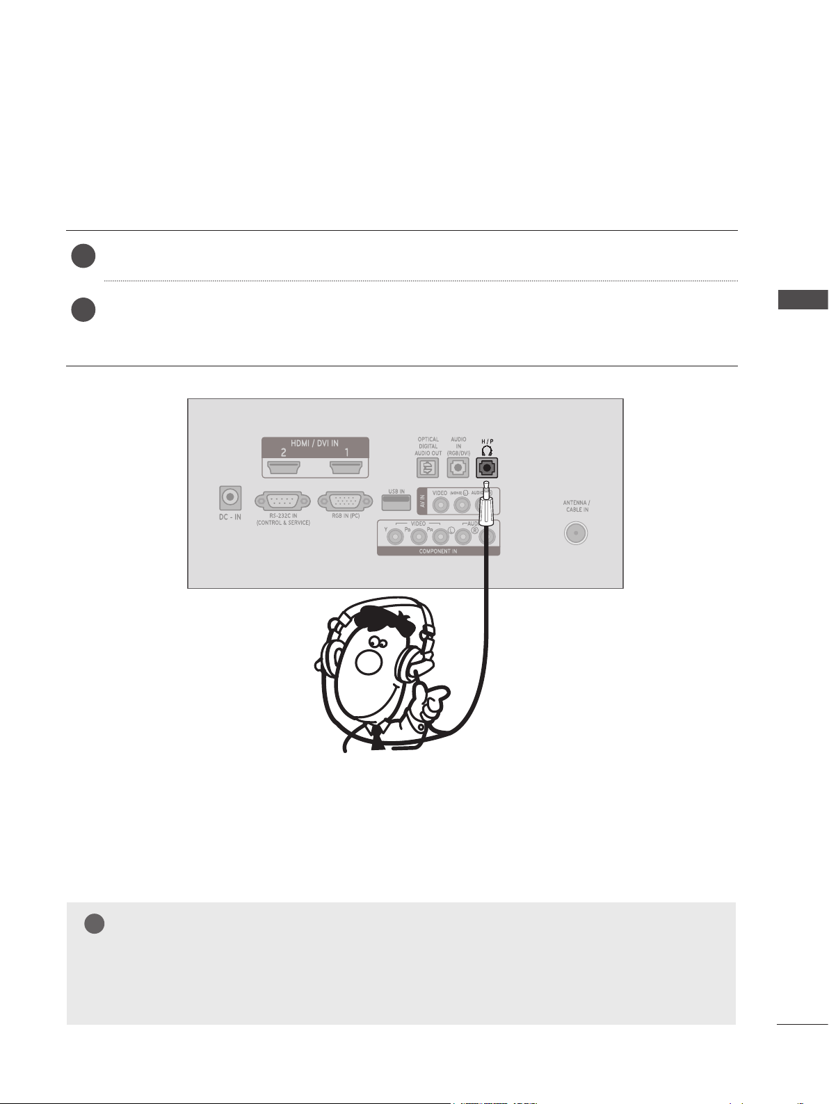
HEADPHONE SETUP
You can listen to sound through headphones plugged into the headphone jack.
Plug the headphone into the headphone socket (H/P).
1
To adjust the headphone volume, press the VOL + or - button. If you press the MUTE button,
2
the sound from the headphone is switched off.
EXTERNAL EQUIPMENT SETUP
NOTE
!
►AUDIO menu items are disabled when headphones are connected.
►Optical Digital Audio Out is not available when headphones are connected.
25
Page 26
EXTERNAL EQUIPMENT SETUP
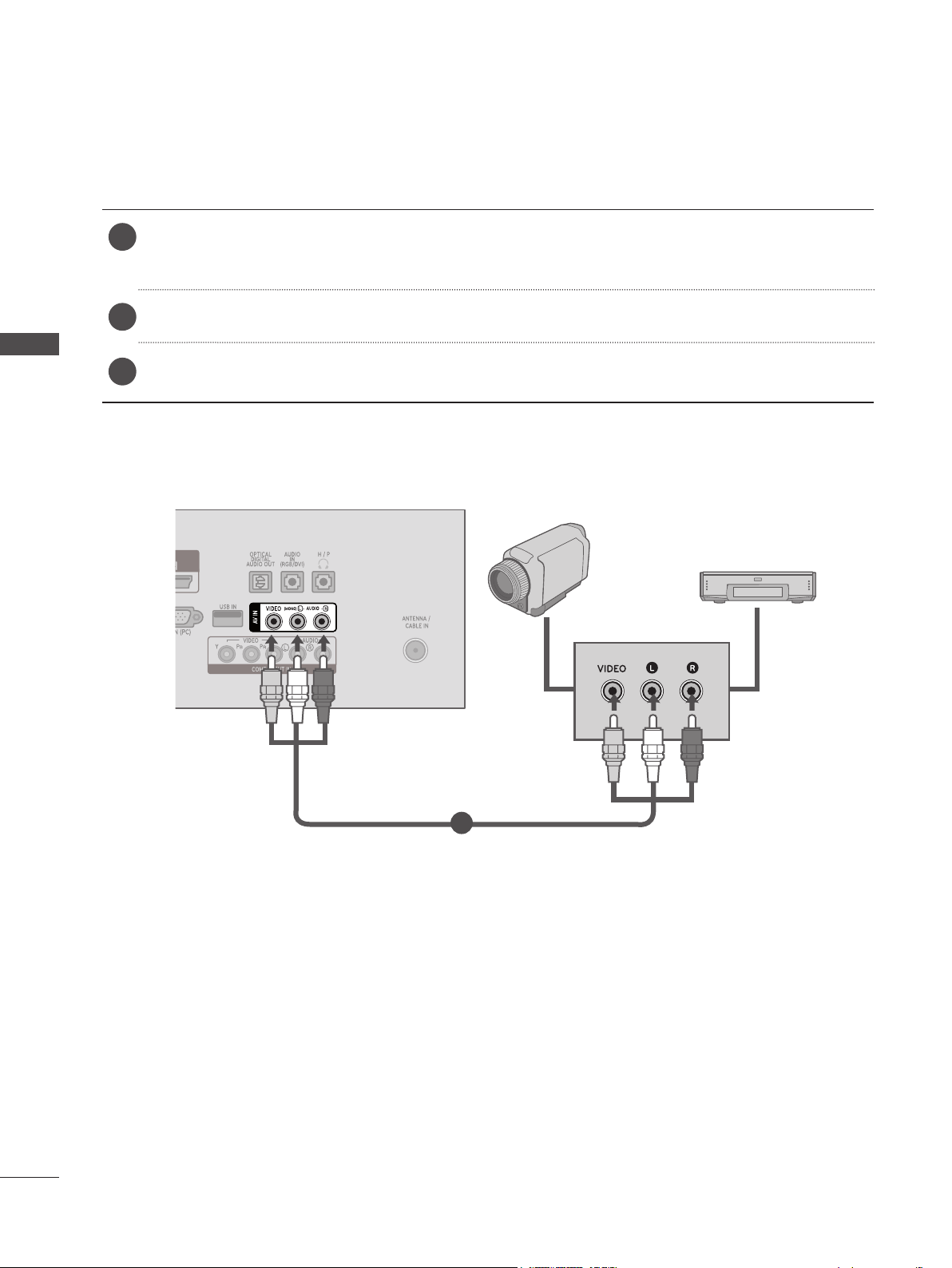
OTHER A/V SOURCE SETUP
Connect the AUDIO/VIDEO jacks between set and external equipment. Match the jack colors.
1
(Video = yellow, Audio Left = white, and Audio Right = red)
Select AV input source with using INPUT on the remote control.
2
EXTERNAL EQUIPMENT SETUP
Operate the corresponding external equipment. Refer to external equipment operating guide.
3
Camcorder
Video game set
1
26
Page 27
PC SETUP
When using the remote control, aim it at the remote control sensor on the Monitor set.
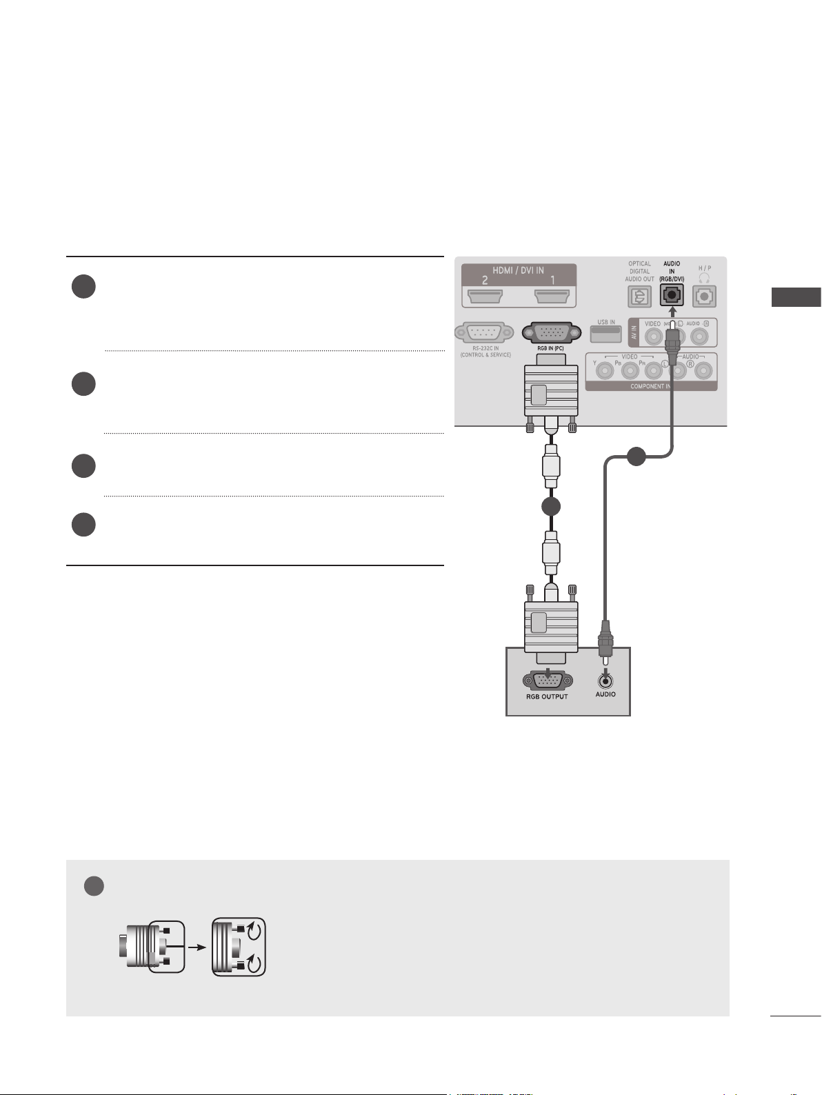
Connecting with a D-sub 15-pin Cable
Connect the signal cable from the monitor output
1
socket of the PERSONAL COMPUTER to the PC
input socket of the Monitor set.
Connect the audio cable from the PC to the AUDIO
2
IN(RGB/DVI) socket of the Monitor set.
EXTERNAL EQUIPMENT SETUP
Press the INPUT to select RGB-PC.
3
Switch on the PC, and the PC screen appears on
4
the set. The set can be operated as a PC monitor.
2
1
NOTE
!
►Connect the signal input cable and tighten it by turning the
screws clockwise.
27
Page 28
EXTERNAL EQUIPMENT SETUP
Connecting with an HDMI to DVI Cable
Connect the DVI output of the PC to the HDMI/DVI
1
EXTERNAL EQUIPMENT SETUP
IN1 or HDMI/DVI IN2 jack on the Monitor set.
Connect the PC audio output to the AUDIO IN
2
(RGB/DVI) jack on the Monitor set.
Turn on the PC and the set.
3
1 2
Select HDMI 1 or HDMI 2 input source using the
4
INPUT on the remote control.
NOTE
!
►If you want to use HDMI-PC mode, you must set the input label to PC mode.
28
►Connect the signal input cable and tighten it by turning the
screws clockwise.
Page 29
Connecting with an HDMI to HDMI Cable
Connect the HDMI output of the PC to the HDMI/
1
DVI IN1 or HDMI/DVI IN2 jack on the Monitor set.
Turn on the PC and the Monitor set.
2
Select HDMI 1 or HDMI 2 input source using INPUT
3
on the remote control.
EXTERNAL EQUIPMENT SETUP
1
NOTE
!
►Check that your HDMI cable is a high speed HDMI cable. If the HDMI cables are not high speed,
flickering or no screen display can result.
►If you want to use HDMI-PC mode, you must set the input label to the PC mode.
29
Page 30
EXTERNAL EQUIPMENT SETUP
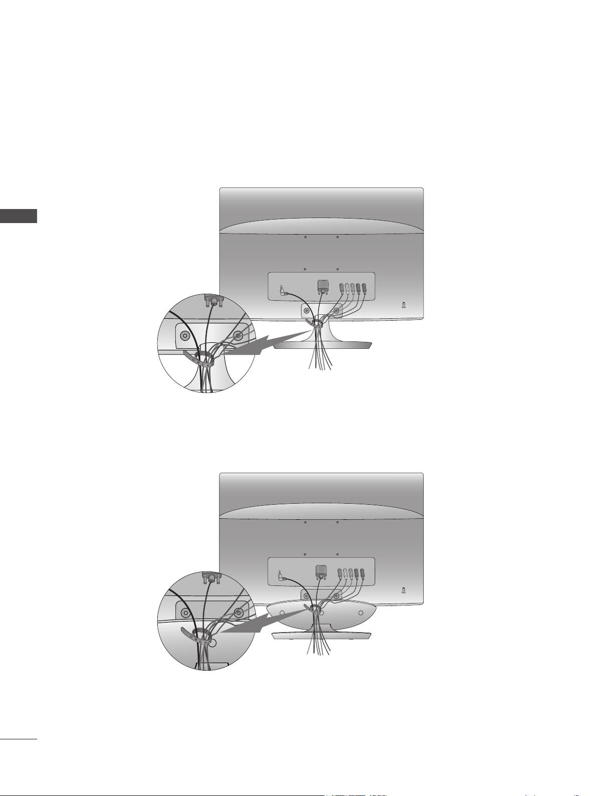
BACK COVER WIRE ARRANGEMENT
Tie cables together for better cable management as shown in the illustration below.
M2080D / M2280D / M2380D / M2780D
EXTERNAL EQUIPMENT SETUP
M2380DF / M2780DF
30
Page 31

SUPPORTED DISPLAY RESOLUTIONS
RGB[PC] Mode
M2080D
Resolution
640 x 480 31.469 59.94
640 x 480 37.5 75
800 x 600 37.879 60.317
800 x 600 46.875 75
832 x 624 49.725 64.55
1024 x 768 48.363 60
1024 x 768 60.023 75.029
1280 x 1024 63.981 60.02
1600 x 900 60 60
Horizontal
Frequency(kHz)
Vertical
Frequency(Hz)
M2280D / M2380D / M2780D
M2380DF / M2780DF
Resolution
720 x 400 31.468 70.08
640 x 480 31.469 59.94
640 x 480 37.5 75
800 x 600 37.879 60.317
800 x 600 46.875 75.0
1024 x 768 48.363 60.0
1024 x 768 60.023 75.029
1152 x 864 67.500 75.000
1280 x 1024 63.981 60.02
1280 x 1024 79.976 75.025
1680 x 1050 64.674 59.883
1680 x 1050 65.290 59.954
1600 x 1200 75.0 60.0
1920 x 1080 67.5 60
Horizontal
Frequency(kHz)
Vertical
Frequency(Hz)
EXTERNAL EQUIPMENT SETUP
HDMI/DVI - PC Mode
M2080D
Resolution
640 x 480 31.469 59.94
640 x 480 37.5 75
800 x 600 37.879 60.317
800 x 600 46.875 75
832 x 624 49.725 64.55
1024 x 768 48.363 60
1024 x 768 60.023 75.029
1280 x 1024 63.981 60.02
1600 x 900 60 60
Horizontal
Frequency(kHz)
Vertical
Frequency(Hz)
M2280D / M2380D / M2780D
M2380DF / M2780DF
Resolution
720 x 400 31.468 70.08
640 x 480 31.469 59.94
640 x 480 37.5 75
800 x 600 37.879 60.317
800 x 600 46.875 75.0
1024 x 768 48.363 60.0
1024 x 768 60.023 75.029
1152 x 864 67.500 75.000
1280 x 1024 63.981 60.02
1280 x 1024 79.976 75.025
1680 x 1050 64.674 59.883
1680 x 1050 65.290 59.954
1600 x 1200 75.0 60.0
1920 x 1080 67.5 60
Horizontal
Frequency(kHz)
Vertical
Frequency(Hz)
31
Page 32

EXTERNAL EQUIPMENT SETUP
HDMI/DVI - DTV Mode Component Mode
Resolution
720 x 480
EXTERNAL EQUIPMENT SETUP
720 x 576 31.25 50
1280 x 720 37.500 50
1280 x 720
1920 x 1080
1920 x 1080 28.125 50.00
1920 x 1080 27 24
1920 x 1080 33.75 30.00
1920 x 1080 56.250 50
1920 x 1080
NOTE
!
Horizontal
Frequency(kHz)
31.469
31.5
44.96
45
33.72
33.75
67.43
67.5
Vertical
Frequency(Hz)
59.94
60
59.94
60
59.94
60
59.94
60
Resolution
720 x 480 15.73 59.94
720 x 480 15.75 60.00
720 x 576 15.625 50.00
720 x 480 31.47 59.94
720 x 480 31.50 60.00
720 x 576 31.25 50.00
1280 x 720 44.96 59.94
1280 x 720 45.00 60.00
1280 x 720 37.50 50.00
1920 x 1080 33.72 59.94
1920 x 1080 33.75 60.00
1920 x 1080 28.125 50.00
1920 x 1080 56.25 50
1920 x 1080 67.432 59.94
1920 x 1080 67.5 60.00
Horizontal
Frequency(kHz)
Vertical
Frequency(Hz)
►Avoid keeping a fixed image on the screen for
prolonged periods of time. Fixed images may
become permanently imprinted on the screen.
Use a screen saver when possible.
► There may be interference relating to resolution,
vertical pattern, contrast or brightness in PC
mode. Change the PC mode to another resolution
or change the refresh rate or adjust the brightness
and contrast on the menu until the picture is clear.
If the refresh rate of the PC graphic card cannot
be changed, change the PC graphic card or consult the manufacturer of the PC graphic card.
► The synchronization input waveform for horizontal
and vertical frequencies are separate.
► Connect the signal cable from the monitor output
port of the PC to the RGB (PC) port of the set or
the signal cable from the HDMI output port of the
PC to the HDMI/DVI IN port on the Monitor set.
► Connect the audio cable from the PC to the audio
input on the Monitor set. (Audio cables are not
included with the Monitor set.)
► If the graphic card on the PC does not output
analog and digital RGB simultaneously, connect
either the RGB or HDMI/DVI IN to display the PC
output on the Monitor set.
► If the graphic card on the PC does output analog
and digital RGB simultaneously, set the Monitor
set to either RGB or HDMI. (The other mode is
Monitor set to plug-and-play automatically by the
Monitor set.)
► DOS mode may not work depending on the video
card if you use an HDMI to DVI cable.
► If you use an RGB-PC cable that is too long, there
may be interference on the screen. We recommend using under 5m of cable.
32
Page 33

WATCHING TV/CHANNEL CONTROL
REMOTE CONTROL KEY FUNCTIONS
When using the remote control, aim it at the remote control sensor on the set.
ꔰ(POWER)
ENERGY
SAVING
TV/PC
INPUT
Auto Config.
0 to 9 number
button
LIST
FLASHBK
MENU
INFO
Switches the set on from standby or off to standby.
Adjusts the Energy Saving. (► P. 49)
Selects TV or PC mode.
Cycles through external input modes.
Automatically adjusts picture position and minimizes image instability.
Selects a channel.
Selects numbered items in a menu.
Displays the channel table. (► P. 42)
Tunes to the last channel viewed.
Selects a menu.
Clears all on-screen displays and returns to TV viewing
from any menu. (► P. 38)
Shows the present screen information.
WATCHING TV/CHANNEL CONTROL
Q. MENU
THUMBSTICK
(Up/Down/Left/Right)
ENTER
BACK
EXIT
Colored
buttons
Selects the desired quick menu source. (Aspect Ratio,
Picture Mode, Sound Mode, Audio, Sleep Timer, Del/
Add/Fav, Caption, USB Device). (► P.37)
Allows you to navigate the on-screen menus and adjust
the system settings to your preference.
Accepts your selection or displays the current mode.
Allows the user to move return one step in an interactive application or other user interaction function.
Clears all on-screen displays and returns to TV viewing
from any menu
Accesses special functions in some menus.
33
Page 34

WATCHING TV/CHANNEL CONTROL
VOLUME
UP/DOWN
MARK
RATIO
WATCHING TV/CHANNEL CONTROL
MUTE
CHANNEL
UP/DOWN
PAGE
UP/DOWN
USB Menu
Control
Buttons
Adjusts the volume.
Scrolls through programmed favorite channels.
FAV
(► P. 43)
Checks and un-checks programs in the USB menu.
Selects your desired Aspect Ratio of picture.
Switches the sound on or off.
Changes the channel.
Moves from one full set of screen information to the
next one.
Controls USB menu.
(Photo List, Music List and Movie List).
34
Installing Batteries
■ Open the battery compartment cover on the back side of the
remote and install the batteries matching correct polarity
(
+with +,-with -
■ Install two 1.5 V AAA batteries. Do not mix old or used bat-
teries with new ones.
■ Close cover.
■ To remove the batteries, perform the installation actions in
reverse.
)
Page 35

TURNING ON THE TV
- When your TV is turned on, you will be able to use its features.
Connect the power cord and switch the AC power control switch on the TV to on. The TV
1
switches to standby mode.
■ To turn the TV on from standby mode, press the ꔰ / I, INPUT or CH▲▼ button on the TV
or press POWER, INPUT, CHꕭꕮor NUMBER (0 to 9) on the remote control.
Select the viewing source by using the INPUT button on the remote control.
2
■ This TV is programmed to remember which power state it was last set to, even if the power
cord is out.
3
When finished using the TV, press the POWER button on the remote control. The TV reverts to
standby mode.
NOTE
!
►If you intend to be away on vacation, disconnect the power plug from the wall power outlet.
►If you do not complete the initial setting, it will appear whenever the TV is switched on until the
initial setting procedure is completed.
►If the TV is unplugged once or turns off with the AC power control switch on the TV, you will need
to reset the Clock function.
WATCHING TV/CHANNEL CONTROL
CHANNEL SELECTION
Press CH ꕭ ꕮ or the NUMBER buttons to select a channel.
1
VOLUME ADJUSTMENT
Press VOL(+ or -) to adjust the volume.
1
If you wish to switch the sound off, press MUTE.
2
You can cancel this function by pressing MUTE or VOL(+ or -).
35
Page 36

WATCHING TV/CHANNEL CONTROL
INITIAL SETTING
This function guides the user to easily set the essential items for viewing the TV for the first time. It can
also be activated from the user menus.
■ The default selection is “Home Use”. We recommend keeping the TV set to the “Home Use” mode
for the best picture in your home environment.
■ “Store Demo” mode is only intended for use in retail environments. Customers can adjust the
“Picture menu - Picture mode” manually while inspecting the TV, but the TV will automatically
return to preset instore mode after 5 minutes.
■ “Store Demo” mode is an optimal setting for displaying at stores. “Store Demo” mode initializes
the TV to set the image quality.
■ You can also adjust Initial Setting in the OPTION menu.
WATCHING TV/CHANNEL CONTROL
Step1. Welcome
Step4. Setting the Time
WELCOME
WELCOME!
Thank you for choosing LG
Next
1
Enter
Step2. Selecting a Language
Language
English
Español
Français
한국어
Previsous
Next
1
Enter
Select Menu Language.
Step3. Setting the Mode
Time Setting
Current Time Setting
Month
Date
Year
Hour
Minute
Time Zone
Daylight Saving
1
Select Auto or Manual.
2
Enter
Step5. Auto Tuning
◄ Auto ►
----
--
--
--
--
Eastern
Auto
NextPrevisous
Select desired time
option.
36
1
Mode Setting
Selecting the environment.
Choose the setting mode you want.
Store Demo
Select [Home Use] to use this TV at home. To use this
TV at Store, select [Store Demo].
Previsous
Enter
Select Home Use.
Home Use
Next
1
Enter
Auto Tuning
Before starting,
be sure that the
TV antenna is connected.
Previsous
Next
Check your antenna connection
and start Auto Tuning.
Page 37

QUICK MENU
Your TV's OSD (On-Screen Display) may differ slightly from what is shown in this manual.
Q.Menu (Quick Menu) is a menu of features users might use frequently.
◄ Aspect Ratio ►
16:9
ꔬ Aspect Ratio: Selects your desired picture format.
ꕧ Picture Mode: Selects your desired Picture Mode.
ꕩ Sound Mode:: Selects the desired preset sound setting.
ꕁ Audio: Selects the sound output.
ꔑ Sleep Timer: Sets the sleep timer.
ꕀDel/Add/Fav: Selects the channel you want to add/delete or add the channel to the Favorite List.
ꕢ Caption: Selects on or off.
ꔧ USB Device: Selects “Eject” in order to eject a USB device.
WATCHING TV/CHANNEL CONTROL
2
3
1
Display each menu.
Make appropriate adjustments.
Enter
or
Return to TV viewing.
• Press BACK to move to the previous menu screen.
37
Page 38

WATCHING TV/CHANNEL CONTROL
ON-SCREEN MENU SELECTION AND ADJUSTMENT
Your set's OSD (On-Screen Display) may differ slightly from what is shown in this manual.
CHANNEL
Auto Tuning
Manual Tuning
Channel Edit
Move
Enter
PICTURE
Aspect Ratio : 16:9
Picture Wizard
ꕫ Energy Saving : Off
Picture Mode : Vivid
• Backlight 100
• Contrast 100
• Brightness 50
• Sharpness 70
Move Move
Enter Enter
AUDIO
Auto Volume : O ff
Clear Voice II : Off
• Level 3
Balance 0
Sound Mode : Standard
• Surround X : Off
• Treble 50
• Bass 50
WATCHING TV/CHANNEL CONTROL
OPTION
Menu Language : English
Audio Language : English
Input Label
Key Lock : Off
Caption : Off
Set ID : 1
Power Indicator : On
Demo Mode : Off
Lock System : Off
Set Password
Block Channel
Movie Rating
TV Rating-Children
TV Rating-General
Downloadable Rating
Input Block
Move Enter
CHANNEL
OPTION
Move Move Move
Enter Enter Enter
PICTURE
INPUTLOCK
TV
AV
Component
RGB-PC
HDMI1
HDMI2
LOCK
AUDIO
INPUT
TIME
USB
TIME
Clock
Off Time : Off
On Time : Off
Sleep Timer : Off
USB
Photo List
Music List
Movie List
DivX Reg. Code
Deactivation
Move
Enter
38
2
3
1
MENU
Enter
Enter
Accept the current selection..
Display each menu.
Select a menu item.
• Press MENU or EXIT to close the menu window.
• Press BACK to move to the previous menu screen.
Page 39

AUTO SCAN (AUTO TUNING)
Use this to automatically find and store all available channels. Automatically finds all channels available
through antenna or cable inputs, and stores them in memory on the channel list.
2
3
4
CHANNEL CHANNEL
Auto Tuning ꔋ Auto Tuning ꔋ
Auto Tuning
Manual Tuning
Channel Edit
1
MENU
Move Move
Enter Enter
➩
Select CHANNEL.
• The TV will ask for a password if parental
Auto Tuning
Manual Tuning
Channel Edit
Check your antenna connection.
The previous channel information
will be updated during Auto
Tuning.
Yes
No
WATCHING TV/CHANNEL CONTROL
control has been activated (Lock Menu).
Use the password you set up in the Lock
Enter
Select Auto Tuning.
Menu to allow a channel search.
• When setting the Auto Tuning or Manual
Tuning, the number of maximum chan-
Enter
Select Yes.
nels you can store is 1,000. This number
is subject to change depending on the
broadcasting signal environment.
Enter
Run Auto tuning.
• Press MENU or EXIT to close the menu window.
• Press BACK to move to the previous menu screen.
39
Page 40

WATCHING TV/CHANNEL CONTROL
ADD/DELETE CHANNEL (MANUAL TUNING)
When selecting DTV or CADTV input signal in the Manual Tuning menu, you can view the on-screen
signal strength monitor to see the quality of the signal being received.
CHANNEL CHANNEL
Auto Tuning
Manual Tuning ꔋ Manual Tuning ꔋ
Manual Tuning
Channel Edit
WATCHING TV/CHANNEL CONTROL
1
MENU
Select CHANNEL.
Move Move
Enter Enter
Auto Tuning
Manual Tuning
➩
Channel Edit
• The TV will ask for a password if parental
control has been activated (LOCK Menu).
◄ DTV
Select channel type and
RF-channel number.
Channel
DTV 2-1
No Signal
Bad Normal Good
2
Add
Close
Use the password you set up in the LOCK
2
Enter
Select Manual Tuning.
Menu to allow a channel search.
• When setting the Auto tuning or Manual
tuning, the number of maximum channel
3
Enter
Select DTV, TV, CADTV or CATV.
you can store is 1,000. This number is
subject to change depending on the
broadcasting signal environment.
40
4
5
6
Enter
Enter
Select channel you want to add or delete.
Select Add or Delete.
• Press MENU or EXIT to close the menu window.
• Press BACK to move to the previous menu screen.
Page 41

CHANNEL EDITING
The channels in the Channel Edit List are displayed in black and the channels deleted from the Channel
Edit List are displayed in blue. When a channel number is deleted, it means that you will be unable to
select it using CH ꕭꕮ button during TV viewing. If you wish to select the deleted channel, directly enter
the channel number with the NUMBER buttons or select it in the Channel Edit menu.
1
2
3
4
MENU
Enter
Enter
BLUE
CHANNEL
Auto Tuning
Manual Tuning
Channel Edit ꔋ
Channel Edit
Move
Enter
Select CHANNEL.
Select Channel Edit.
Select a channel.
Add or delete a channel.
➩
2-1
ch. Change Navigation Page Change Previous
DTV TV CADTV CATV
2-0
4-0
6-0
8-0
10-0
12-0
14-0
51-0
3-0
5-0
7-0
9-0
11-0
13-0
30-0
63-0
Add / Delete
WATCHING TV/CHANNEL CONTROL
5
Enter
• Press MENU or EXIT to close the menu window.
• Press BACK to move to the previous menu screen.
41
Page 42

WATCHING TV/CHANNEL CONTROL
CHANNEL LIST
You can check which channels are stored in the memory by displaying the channel label.
Channel List
• This padlock is displayed when
the channel is locked with
parental control.
WATCHING TV/CHANNEL CONTROL
ꔖ
TV 2-0
TV 3-0
TV 4-0
ꔋ
Exit
CHANNEL LIST
1
Display the Channel List.
SELECTING A CHANNEL IN THE CHANNEL LIST
1
Select a channel.
2
Enter
Switch to the chosen channel number.
PAGING THROUGH A CHANNEL LIST
1
Turn the pages.
2
BACK
Return to TV viewing.
42
Page 43

FAVORITE CHANNEL SETUP
Favorite Channels are a convenient feature that let you quickly select channels of your choice without waiting
for the TV to select all the channels in between. To tune to a favorite channel, press FAV (Favorite) repeatedly.
◄ Del / Add / Fav ►
Add
FAVORITE CHANNEL LIST
♥ Favourite List
TV
2-1
TV
3-1
TV
4-1
ꔋ
Displaying the Favorite Channel List
1
1
or
Select your desired channel.
2
Select Del/Add/Fav.
3
Select Favourite.
4
Return to TV viewing.
Display the Favorite channel list.
WATCHING TV/CHANNEL CONTROL
Exit
Selecting a Channel in the Favorite Channel List
1
Select a channel.
2
Enter
Switch to the chosen channel number.
Paging through a Favorite Channel List
1
Turn the pages.
2
BACK
Return to TV viewing.
43
Page 44

WATCHING TV/CHANNEL CONTROL
BRIEF INFORMATION
Brief Info shows the present screen information.
1
Show the Brief Info on the screen.
2
Return to TV viewing
BACK
WATCHING TV/CHANNEL CONTROL
1
DTV
DOLBY DIGITAL
HD
CNN
11-1
2 3 4 5 6 7
Brief Info Title Test..
Tue, Mar 30, 2010 09:45 PM 10:45 PM
Multilingual Caption TV-PG D L S VD
CC
16 : 9
09:45 PM
8
Banner information
1 8
Program title
2
Day, Month, Year
3
Program start time
4
5
Program progress bar
6
Program finish time
Present time
7
CC
4 : 3
16 : 9
Multilingual: The program contains two or more audio
services. Use the Q.MENU menu to select wanted Audio.
Dolby Digital: The program contains a Dolby Digital audio
D
signal in TV, HDMI input source and DivX.
Caption: The program contains one or more caption
services. Use the Q.MENU menu to select the desired
Closed caption.
The original aspect ratio of the video is 4:3
The original aspect ratio of the video is 16:9 (wide)
44
480i
480p
720p
1080i
1080p
The video resolution is 720x480i
The video resolution is 720x480p
The video resolution is 1280x720p
The video resolution is 1920x1080i
The video resolution is 1920x1080p
V-Chip: The program contains V-Chip information. Refer
to the LOCK menu: A (Age), D (Dialogue), L (Language),
S (Sex), V (Violence), FV (Fantasy Violence).
Page 45

INPUT LIST
TV, HDMI, AV, Component and RGB-PC can be recognized by a detect pin and thus enabled only when
an external device receives the approved voltage..
TV
AV
Component
WATCHING TV/CHANNEL CONTROL
HDMI 2
INPUT
1
Enter
Select the desired input source.
You can also select the desired input source in the INPUT menu.
HDMI 1
RGB-PC
• TV: Watch over-the-air, cable and digital cable broadcasts.
• AV: Watch a VCR or external equipment.
• Component: Watch a DVD player or a digital set-top box.
• RGB-PC: View PC input.
• HDMI 1, HDMI 2: Watch high definition devices.
45
Page 46

PICTURE CONTROL
ASPECT RATIO SELECTION
Image signals can be displayed in various picture formats: 16:9, Just Scan, Set By Program , 4:3, Zoom
and Cinema Zoom. You can adjust the enlarge proportion using ꕭꕮ button. This function works with the
signals listed below.
Note that if a fixed image is displayed on the screen for a long time, that image may become imprinted
on the screen and remain visible.
1
Select Aspect Ratio.
2
PICTURE CONTROL
Select the desired picture format.
• You can also adjust Aspect Ratio in the PICTURE
and Q.MENU menu.
• Press RATIO repeatedly to select the desired picture
format.
• 16:9
Adjust the picture horizontally, in a linear proportion to fill the entire screen.
• Just Scan
Normally, the edges of video signals are cropped
1-2%. Just Scan turns off this cropping and
shows the complete video.
Note: if there is noise on the edges of the
original signal, it will be visible when Just Scan
is activated.
Just Scan operates only in DTV/CADTV/
Component/HDMI-DTV(720p/1080i/1080p)
input source.
Just Scan
46
Page 47

• Set By Program
Selects the proper picture proportion to match
the source’s image.
(4:3 4:3)
• Cinema Zoom 1 to 16
Choose Cinema Zoom when you want to
enlarge the picture in correct proportion.
Note: When enlarging or reducing the picture,
the image may become distorted.
Set By Program
(16:9 16:9)
Set By Program
• 4:3
Choose 4:3 when you want to view a picture
with an original 4:3 aspect ratio.
• Zoom
Choose Zoom when you want to view the picture without any alteration. However, the top
and bottom portions of the picture will be
cropped.
< or > : Adjusts proportion of Cinema Zoom.
The adjustment range is 1 to 16.
ꕭ or ꕮ: Moves the image on the screen.
PICTURE CONTROL
When adjusting in Q.MENU menu,
a. < or > : Adjust proportion of Zoom.
b. ꕭ or ꕮ: Move the image on the screen.
47
Page 48

PICTURE CONTROL
PICTURE WIZARD
This feature lets you adjust the picture quality of the original image.
Use this to calibrate the screen quality by adjusting the Black and White Level, etc. You can calibrate the
screen quality by easily following each step.
When you adjust the image to Low, Recommended or High, you can see an example of the changes
you've made.
PICTURE
Aspect Ratio : 16:9
Picture Wizard ꔋ
Picture Wizard
ꕫ Energy Saving : Off
Picture Mode : Vivid
• Backlight 100
• Contrast 100
• Brightness 50
PICTURE CONTROL
1
MENU
• Sharpness 70
Select PICTURE.
Move
Enter
➩
Picture Wizard
With Picture Wizard, you can adjust the picture quality of the
original image.
Previous
Next
2
EnterEnter
Select Picture Wizard.
3
Enter
Adjust Black level, White level, Color, Tint, Horizontal Sharpness, Vertical Sharpness,
Color Temperature, Dynamic Contrast , Color Gain, Backlight.
48
4
Enter
Select input source to apply the settings.
5
Enter
• Press MENU or EXIT to close the menu window.
• Press BACK to move to the previous menu screaen.
• If you stop the setting before the final step, the changes will not be saved to the set.
• Once the Picture Wizard sets the picture quality, Energy Saving is changed to Off automatically.
Page 49

ꕫ ENERGY SAVING
Reduces the set's power consumption by lowering the backlight level. You can increase the brightness
of your screen by adjusting the Energy Saving level or by setting the Picture Mode.
2
3
4
PICTURE PICTURE
Aspect Ratio : 16:9
Picture Wizard
ꕫ Energy Saving : Off ꔋ ꕫ Energy Saving : Off ꔋ
ꕫ Energy Saving : Off
Picture Mode : Vivid
• Backlight 100
• Contrast 100
• Brightness 50
• Sharpness 70
1
MENU
Enter
Enter
Enter
Select PICTURE.
Select
Select Off, Minimum, Medium, Maximum or Screen Off.
Move Move
ꕫ
Enter Enter
Aspect Ratio : 16:9
Picture Wizard
ꕫ Energy Saving : Off
➩
Picture Mode : Vivid
• Backlight 100
• Contrast 100
• Brightness 50
• Sharpness 70
Energy Saving.
Off ꔋ
Off
Minimum
Medium
Maximum
Screen Off
PICTURE CONTROL
• Press MENU or EXIT to close the menu window.
• Press BACK to move to the previous menu screaen.
• When selecting Screen off, the screen will turn off in 3 seconds.
• If you adjust “Energy Saving-Minimum, Medium, Maximum”, the Backlight feature will not work.
• Press ENERGY SAVING repeatedly to select the appropriate Energy Saving setup.
49
Page 50

PICTURE CONTROL
PRESET PICTURE SETTINGS (PICTURE MODE)
Vivid Maximizes the effect of the video in retail stores. Strengthen the contrast, brightness,
color and sharpness for vivid picture.
Standard This is the optimum viewing condition for general users.
Natural This is the mode to display the most natural screen status.
Cinema This mode optimizes video for watching movie.
Sport This mode emphasizes dynamic video and primary colors (e.g. white, uniforms, grass, sky
blue, etc.) by realizing the optimal image settings for sports.
Game This is the mode for fast response speeds for video games.
Expert 1,2 User-defined settings.
PICTURE PICTURE
PICTURE CONTROL
1
MENU
Aspect Ratio : 16:9
Picture Wizard
ꕫ Energy Saving : Off
Picture Mode : Vivid ꔋ Picture Mode : Vivid ꔋ
Picture Mode : Vivid
• Backlight 100
• Contrast 100
• Brightness 50
• Sharpness 70
Select PICTURE.
Move Move
Enter Enter
Aspect Ratio : 16:9
➩
Picture Wizard
ꕫ Energy Saving : Off
Picture Mode : Vivid
• Backlight 100
• Contrast 100
• Brightness 50
• Sharpness 70
Vivid ꔋ
Vivid
Standard
Natural
Cinema
Sport
Game
ꕬ Expert 1
ꕬ Expert 2
2
Enter
Select Picture Mode.
3
Enter
Select Vivid, Standard, Natural, Cinema, Sport or Game
4
Enter
50
• Press MENU or EXIT to close the menu window.
• Press BACK to move to the previous menu screaen.
• Picture Mode adjusts the set for the best picture appearance. Select the preset value in the Picture
Mode menu based on the channel category.
• You can also adjust Picture Mode in the Q. Menu.
Page 51

MANUAL PICTURE ADJUSTMENT-USER MODE
Backlight Adjusts the brightness of LCD panel.
Contrast Adjusts the difference between light and dark levels.
Brightness Adjusts the brightness of the screen.
Sharpness Adjusts the clearness of the screen.
Color Adjusts the color.
Tint Adjusts the tint.
2
3
4
PICTURE PICTURE
Aspect Ratio : 16:9
Picture Wizard
ꕫ Energy Saving : Off
Picture Mode : Vivid (User) ꔋ Picture Mode : Vivid (User) ꔋ
Picture Mode : Vivid
• Backlight 100
• Contrast 100
• Brightness 50
• Sharpness 70
1
MENU
Enter
Enter
Enter
Select PICTURE.
Select Picture Mode.
Select Vivid, Standard, Natural, Cinema, Sport or Game
Select Backlight, Contrast, Brightness, Sharpness, Color or Tint
Move Move
OK OK
Aspect Ratio : 16:9
Picture Wizard
ꕫ Energy Saving : Off
➩
Picture Mode : Vivid
• Backlight 100
• Contrast 100
• Brightness 50
• Sharpness 70
Vivid ꔋ
Vivid
Standard
Natural
Cinema
Sport
Game
ꕬ Expert 1
ꕬ Expert 2
PICTURE CONTROL
5
Enter
Make appropriate adjustments.
6
Enter
• Press MENU or EXIT to close the menu window.
• Press BACK to move to the previous menu screaen.
NOTE
!
►You cannot adjust color and tint in the RGB-PC/HDMI-PC mode.
►When the Expert 1/2 is selected, you can select Backlight, Contrast, Brightness, H Sharpness, V
Sharpness, Color or Tint .
51
Page 52

PICTURE CONTROL
PICTURE IMPROVEMENT TECHNOLOGY
You can calibrate the screen for each Picture Mode or set the video value according to the special video
screen. You can set the video value differently for each input. To reset to the factory default screen after
making adjustments to each video mode, execute the “Picture Reset” function for each Picture Mode.
PICTURE PICTURE
• Contrast 100
• Brightness 50
• Sharpness 70
• Color 50
• Tint 0
• Advanced Control ꔋ • Advanced Control ꔋ
• Advanced Control
• Picture Reset
Screen(RGB-)PC
Move Move
OK OK
• Contrast 100
• Brightness 50
➩
• Sharpness 70
• Color 50
• Tint 0
• Advanced Control
• Picture Reset
Screen(RGB-)PC
Color Temperarute
Dynamic Contrast
Dynamic Color
Noise Reduction
Gamma
Black Level
Film Mode
◄ Medium ►
High
High
Medium
Medium
Auto
On
PICTURE CONTROL
Close
1
MENU
Select PICTURE.
2
Enter
Select Advanced Control.
3
Enter
Select your desired options.
52
4
Make appropriate adjustments.
• Press MENU or EXIT to close the menu window.
• Press BACK to move to the previous menu screaen.
Page 53

EXPERT PICTURE CONTROL
By segmenting categories, Expert 1 and Expert 2 provide more categories which users can set as they
see fit, offering optimal picture quality. This may also be used to help a professional optimize the set
performance using specific videos.
2
3
PICTURE
Aspect Ratio : 16:9
Picture Wizard
ꕫ Energy Saving : Off
Picture Mode : ꕬ Expert 1 ꔋ
Picture Mode : Standard
• Backlight 70
• Contrast 90
• Brightness 50
• H Sharpness 70
1
MENU
Enter
Enter
Move
Select PICTURE.
Select Picture Mode.
Select ꕬ Expert 1 or ꕬ Expert 2.
Enter
Vivid
Standard
Natural
Cinema
Sport
Game
ꕬ Expert 1 ꔋ
ꕬ Expert 1
ꕬ Expert 2
➩
PICTURE
• Contrast 80
• Brightness 50
• H Sharpness 50
• V Sharpness 50
• Color 50
• Tint 0
• Expert Control ꔋ
• Advanced Control
• Picture Reset
Move
Enter
Dynamic Contrast
Nosie Reduction
Gamma
Black Level
Film Mode
Color Standard
Expert Pattern
Color Filter
Color Temperature
◄ Off ►
Off
Medium
Auto
On
HD
Off
Off
medium
PICTURE CONTROL
Close
4
5
6
Enter
Enter
Select Expert Control.
Select your desired source.
Make appropriate adjustments.
• Press MENU or EXIT to close the menu window.
• Press BACK to move to the previous menu screaen.
53
Page 54

PICTURE CONTROL
Color Temperature
Dynamic Contrast
Dynamic Color
Noise Reduction ■ Reduces screen noise without compromising video quality.
PICTURE CONTROL
Gamma
Black Level
■ Set to warm to enhance hotter colors such as red, or set to cool to
enhance cooler colors such as blue.
■ Adjusts the contrast to keep it at the best level according to the
brightness of the screen. The picture is improved by making bright
parts brighter and dark parts darker.
■ Adjusts screen colors so that they look livelier, richer and clearer.
This feature enhances hue, saturation and luminance so that red,
blue, green and white look more vivid.
• Low: Makes dark and middle gray level areas of the picture brighter.
• Medium: Express original picture levels.
• High: Makes dark and middle gray level area of the picture darker.
■ You can adjust the brightness of dark areas and middle gray level
areas of the picture.
• Low: The reflection of the screen gets darker.
• High: The reflection of the screen gets brighter.
■ Sets black level of the screen to a proper level.
■ This function enables you to select 'Low' or 'High' in the following
mode: AV (NTSC-M), HDMI or Component. Otherwise, 'Black level'
is set to 'Auto'.
54
Film Mode
Color Standard ■ Convert the color of a different video to HD color.
Color Filter
Expert Pattern
■ Makes video clips recorded in film look more natural by eliminating
jitter effect.
■ Filters the specific colors of the video.
You can use the RGB filter to set color saturation and hue accurately.
■ This is the pattern necessary for expert adjustment.
■ This function is enabled in "Picture Mode - Expert" when you watch
DTV.
Page 55

White Balance
Color Management System
■ Adjusts the overall color of the screen.
a. Method : 2 Points
- Pattern: Inner, Outer
- Red/Green/Blue Contrast, Red/Green/Blue Brightness: The
adjustment range is -50 to +50.
b. Method : 10 Point IRE
- Pattern: Inner, Outer
- IRE (Institute of Radio Engineers) is the unit to display the size of
the video signal and can be set among 10, 20, 30 - 100. You can
adjust Red, Green or Blue according to each setting.
- Luminance: This function displays calculated luminance value for
2.2 gamma. You can input luminance value you want at 100 IRE,
than the target luminance value for 2.2 gamma is displayed at
every 10 steps from 10 IRE to 90 IRE.
- Red/Green/Blue: The adjustment range is -50 to +50.
PICTURE CONTROL
■ A tool used by the experts to make adjustments by using the test
patterns, this does not affect other colors but can be used to selectively adjust the 6 color areas (Red/Green/Blue/Cyan/Mgt/Yellow).
Color difference may not be distinctive even when you make the
adjustments for general video.
Adjusts Red/Green/Blue/Yellow/Cyan/Magenta.
- Red/Green/Blue/Yellow/Cyan/Magenta Color: The adjustment
range is -30 to +30.
- Red/Green/Blue/Yellow/Cyan/Magenta Tint: The adjustment range
is -30 to +30.
- This feature is disabled in RGB-PC and HDMI-PC mode.
55
Page 56

PICTURE CONTROL
PICTURE RESET
Return the settings of the selected Picture Mode to the default factory settings.
PICTURE PICTURE
• Contrast 100
• Brightness 50
• Sharpness 70
• Color 50
• Tint 0
• Advanced Control
• Picture Reset ꔋ • Picture Reset ꔋ
• Picture Reset
Screen(RGB-)PC
Move Move
Enter Enter
• Contrast 100
• Brightness 50
➩
• Sharpness 70
• Color 50
• Tint 0
• Advanced Control
• Picture Reset
Screen(RGB-)PC
All picture setting will be resetted .
?
Continue ?
Yes
No
PICTURE CONTROL
1
MENU
Select Picture.
2
Enter
Select Picture Reset.
3
Enter
Select Yes or No.
4
Enter
56
• Press MENU or EXIT to close the menu window.
• Press BACK to move to the previous menu screaen.
Page 57

SCREEN SETUP FOR PC MODE
Selecting Resolution
To view a normal picture, match the resolution of RGB mode and selection of PC mode.
This function works in RGB-PC mode
<Vertical resolution : 768>
Move
Prev.
Move
Prev.
PICTURE
• Contrast 100
• Brightness 50
• Sharpness 70
• Color 50
• Tint 0
• Advanced Control
• Picture Reset
Screen(RGB-)PC
Screen(RGB - PC)
Move
ꔋ
Enter
➩
SCREEN
Resoluttion
Auto Config.
Position
Size
Phase
Reset
1024 x 768
1280 x 768
1360 x 768
<Vertical resolution : 900>
SCREEN
Resoluttion
Auto Config.
Position
Size
Phase
Reset
1280 x 960
1400 x 900
1600 x 900
PICTURE CONTROL
2
3
4
5
1
MENU
Enter
Enter
Enter
Enter
Select Picture.
Select Screen (RGB-PC).
Select Resolution.
Select the desired resolution.
• Press MENU or EXIT to close the menu window.
• Press BACK to move to the previous menu screaen.
57
Page 58

PICTURE CONTROL
Auto Configure (RGB-PC Mode Only)
Automatically adjusts picture position and minimizes image instability. After adjustment, if the image is
still not correct, your set is functioning properly but needs further adjustment.
Auto Configure
This function is for automatic adjustment of the screen position, clock, and phase The displayed image
will be unstable for a few seconds while the auto configuration is in progress.
1. Using OSD
PICTURE
• Contrast 100
• Brightness 50
• Sharpness 50
• Color 50
• Tint 0
• Advanced Control
PICTURE CONTROL
1
MENU
• Picture Reset
Screen(RGB - PC)
Screen(RGB-)PC
Select PICTURE.
Move
ꔋ
Enter
➩
• If the position of the image is still not correct,
SCREEN
Resolution
Auto Config.
Position
Size
Phase
Reset
Move Prev.
To Set
Yes No
try Auto adjustment again.
2
3
4
Enter
Enter
Enter
Select Screen (RGB-PC).
Select Auto Config.
Select Yes.
• If picture needs to be adjusted again after Auto
adjustment in RGB-PC, you can adjust the
Position, Size or Phase.
5
Enter
Run Auto Config.
• Press MENU or EXIT to close the menu window.
• Press BACK to move to the previous menu screaen.
58
2. Using Auto Config. (Remocon)
This function is available for RGB signals only.
<M2080D>
1
Press Auto Config.
<M2280D/M2380D/M2780D/M2380DF/M2780DF>
Auto in progress
<1600 x 900 Resolution>
1
Press Auto Config.
Auto in progress
<1920 x 1080 Resolution>
!
Auto in progress
For optimal display
change resolution 1600 x 900
<Others Resolution>
!
change resolution 1920 x 1080
Auto in progress
For optimal display
<Others Resolution>
Page 59

Adjustment for Screen Position, Size, Phase
If the picture is not clear after auto adjustment and especially if characters are still shaking, adjust the
picture phase manually.
This function works in RGB-PC mode.
2
3
4
PICTURE
• Contrast 100
• Brightness 50
• Sharpness 50
• Color 50
• Tint 0
• Advanced Control
• Picture Reset
Screen(RGB - PC)
Screen(RGB-)PC
1
MENU
Enter
Enter
Enter
Select PICTURE.
Select Screen (RGB-PC).
Select Position, Size or Phase.
Move
ꔋ
Enter
➩
Make appropriate adjustments.
SCREEN
Resolution
Auto Config.
Position
Size
Phase
Reset
Move Prev.
PICTURE CONTROL
5
Enter
• Press MENU or EXIT to close the menu window.
• Press BACK to move to the previous menu screaen.
59
Page 60

PICTURE CONTROL
Screen Reset
Returns Position, Size and Phase to the factory default settings.
This function works in RGB-PC mode.
PICTURE
• Contrast 100
• Brightness 50
• Sharpness 50
• Color 50
• Tint 0
• Advanced Control
• Picture Reset
PICTURE CONTROL
1
MENU
Screen(RGB-)PC
Select PICTURE.
Move
Enter
➩
SCREEN
Resolution
Auto Config.
Position
Size
Phase
Reset
Move Prev.
To Set
Yes No
2
Enter
Select Screen (RGB-PC).
3
Enter
Select Reset.
4
Enter
Select Yes.
60
5
Enter
Run Reset.
• Press MENU or EXIT to close the menu window.
• Press BACK to move to the previous menu screaen.
Page 61

SOUND CONTROL
AUTO VOLUME LEVELER (AUTO VOLUME)
Auto Volume makes sure that the volume level remains consistent whether you are watching a commercial or a regular TV program. Because each broadcasting station has its own signal conditions, volume
adjustment may be needed every time the channel is changed. This feature allows users to enjoy stable
volume levels by making automatic adjustments for each program.
2
3
AUDIO AUDIO
Auto Volume : Off ꔋ Auto Volume : Off ꔋ
Auto Volume : O ff
Clear Voice II : Off
• Level 3
Balance 0
Sound Mode : Standard
• Surround X : Off
• Treble 50
• Bass 50
Move Move
Enter Enter
➩
Auto Volume : O ff
Clear Voice II : Off
• Level 3
Balance 0
Sound Mode : Standard
• Surround X : Off
• Treble 50
• Bass 50
Off ꔋ
Off
On
SOUND CONTROL
1
MENU
Enter
Enter
Select AUDIO.
Select Auto Volume.
Select On or Off.
4
Enter
• Press MENU or EXIT to close the menu window.
• Press BACK to move to the previous menu screaen.
61
Page 62

SOUND CONTROL
CLEAR VOICE II
By differentiating the human sound range from others, Clear Voice II improves the sound quality of
voices.
AUDIO AUDIO
Auto Volume : O ff
Clear Voice II : Off ꔋ Clear Voice II : Off ꔋ
Clear Voice II : Off
• Level 3
Balance 0
Sound Mode : Standard
• Surround X : Off
• Treble 50
• Bass 50
Move Move
Enter Enter
Auto Volume : O ff
Off
On ꔋ
On
➩
Clear Voice II : Off
• Level 3
Balance 0
Sound Mode : Standard
• Surround X : Off
• Treble 50
• Bass 50
SOUND CONTROL
1
MENU
Select AUDIO.
• If you select “On” for Clear Voice II, the
Surround X feature will not work.
2
Enter
Select Clear Voice II.
• Select levels from ‘-6’ to ’+6’.
3
Enter
Select On or Off.
62
Adjustment for Clear Voice Level Selecting On
4
Enter
Select Level.
5
Enter
Make appropriate adjustments.
• Press MENU or EXIT to close the menu window.
• Press BACK to move to the previous menu screaen.
Page 63
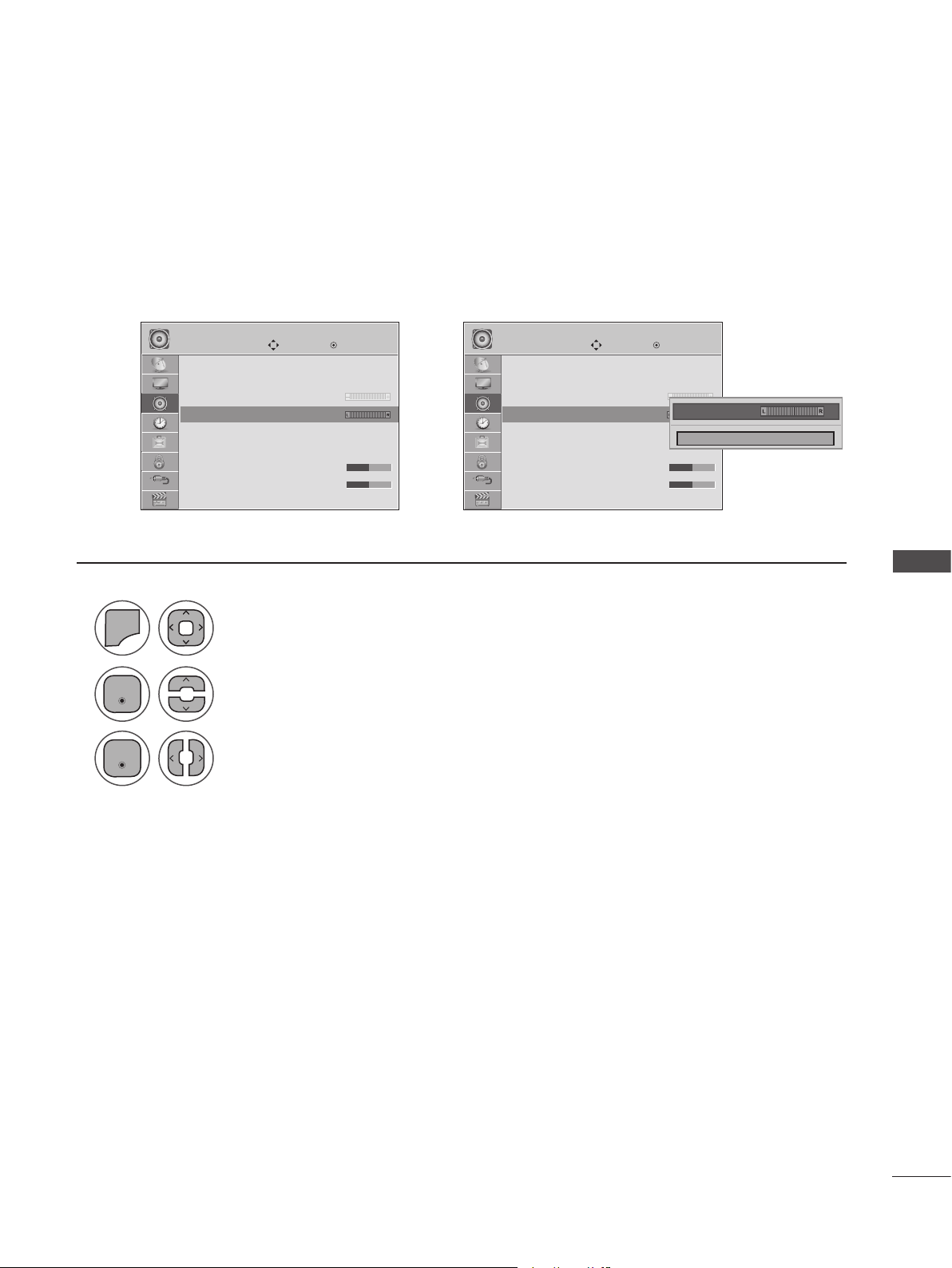
BALANCE
Adjust the left/right sound of the speakers to suit your taste and room situations.
2
3
AUDIO AUDIO
Auto Volume : O ff
Clear Voice II : Off
• Level 3
Balance 0 ꔋ Balance 0 ꔋ
Balance 0
Sound Mode : Standard
• Surround X : Off
• Treble 50
• Bass 50
Move Move
Enter Enter
Auto Volume : O ff
Clear Voice II : Off
• Level 3
➩
Balance 0
Sound Mode : Standard
• Surround X : Off
• Treble 50
• Bass 50
Balance 0 ◄ ►
Close
SOUND CONTROL
1
MENU
Enter
Enter
Select AUDIO.
Select Balance.
Make appropriate adjustments.
• Press MENU or EXIT to close the menu window.
• Press BACK to move to the previous menu screaen.
63
Page 64

SOUND CONTROL
PRESET SOUND SETTINGS-SOUND MODE
You can select your preferred sound setting; Standard, Music, Cinema, Sport or Game and you can also
adjust the Treble or Bass. Sound Mode lets you enjoy the best sound without any special adjustment as
the TV sets the appropriate sound options based on the program content. Standard, Music, Cinema,
Sport and Game are preset for optimum sound quality at the factory.
Standard Offers standard-quality sound.
Music Optimizes sound for listening to music.
Cinema Optimizes sound for watching movies.
Sport Optimizes sound for watching sports events.
Game Optimizes sound for playing video games.
AUDIO AUDIO
Auto Volume : O ff
Clear Voice II : Off
• Level 3
Balance 0
SOUND CONTROL
1
MENU
Sound Mode : Standard ꔋ Sound Mode : Standard ꔋ
Sound Mode : Standard
• Surround X : Off
• Treble 50
• Bass 50
Select AUDIO.
Move Move
Enter Enter
Auto Volume : O ff
Clear Voice II : Off
• Level 3
➩
Balance 0
Sound Mode : Standard
• Surround X : Off
• Treble 50
• Bass 50
Standard ꔋ
Standard
Music
Cinema
Sport
Game
• You can also adjust Sound Mode in the Q Menu.
2
Enter
Select Sound Mode.
3
Enter
Select Standard, Music, Cinema, Sport or Game.
4
Enter
64
• Press MENU or EXIT to close the menu window.
• Press BACK to move to the previous menu screaen.
Page 65

PRESET SOUND SETTINGS-USER MODE
Adjust the sound to suit your taste and room situations.
2
3
4
5
AUDIO AUDIO
Auto Volume : O ff
Clear Voice II : Off
• Level 3
Balance 0
Sound Mode : Standard
• Surround X : Off
• Treble 50 ꔋ • Treble 50 ꔋ
• Treble 50
• Bass 50
1
MENU
Enter
Move Move
Select AUDIO.
Select Sound Mode.
Enter Enter
Auto Volume : O ff
Clear Voice II : Off
• Level 3
➩
Balance 0
Sound Mode : Standard(User)
• Surround X : Off
• Treble 50
• Bass 50
• Surround X
• Treble 50
• Treble 56 ◄ ►
• Bass 50
◄ Off ►
Close
SOUND CONTROL
Enter
Enter
Enter
Select Standard, Music, Cinema, Sport or Game.
Select Treble or Bass.
Make appropriate adjustments.
Surround X
This option enhances sound depth and clarity by maximizing the Surround effect.
1
MENU
2
Enter
3
Enter
4
Enter
Select AUDIO.
Select Surround X.
Select On or off
AUDIO
Auto Volume : O ff
Clear Voice II : Off
• Level 3
Balance 0
Sound Mode : Standard
• Surround X : Off ꔋ
• Surround X : Off
• Treble 50
• Bass 50
Move
• Press MENU or EXIT to close the menu window.
• Press BACK to move to the previous menu screaen.
Enter
• Surround X
• Treble 50
• Bass 50
◄ On ►
Close
65
Page 66

SOUND CONTROL
AUDIO RESET
Return the settings of the selected Sound Mode to the default factory settings.
AUDIOAUDIO
ꔎ
• Level 3
Balance 0
Sound Mode : Standard
• Surround X : Off
• Treble 50
• Bass 50
• Reset ꔋ • Reset ꔋ
• Reset
TV Speaker : On
SOUND CONTROL
1
MENU
Select AUDIO.
➩
• Level 3
Balance 0
Sound Mode : Standard
Resetting sound mode configuration...
• Surround X : Off
• Treble 50
• Bass 50
• Reset
TV Speaker : On
MoveMove
ꔎ
OKOK
2
Enter
Select Reset.
3
Enter
Initialize the adjusted value.
66
• Press MENU or EXIT to close the menu window.
• Press BACK to move to the previous menu screaen.
Page 67

TV SPEAKERS ON/OFF SETUP
You can adjust the SET internal speaker status.
In AV, COMPONENT, RGB and HDMI 1/2 with HDMI to DVI cable, the TV speaker can be operational
even when there is no video signal. If you wish to use an external Hi-Fi system, turn off the SET’s internal speakers.
2
3
4
ꔎ
• Level 3
Balance 0
Sound Mode : Standard
• Surround X : Off
• Treble 50
• Bass 50
• Reset
TV Speaker : On ꔋ
TV Speaker : On
➩
AUDIOAUDIO
• Level 3
Balance 0
Sound Mode : Standard
• Surround X : Off
• Treble 50
• Bass 50
• Reset
TV Speaker : On ꔋ
TV Speaker : On
MoveMove
ꔎ
OKOK
Off
On ꔋ
On
SOUND CONTROL
1
MENU
Enter
Enter
Enter
Select AUDIO.
Select TV Speaker.
Select On or Off.
• Press MENU or EXIT to close the menu window.
• Press BACK to move to the previous menu screaen.
67
Page 68

SOUND CONTROL
STEREO/SAP BROADCAST SETUP
On analog signals, this set can receive MTS stereo programs and any SAP (Secondary Audio Program)
that accompanies the stereo program if the station transmits an additional sound signal. Mono sound
is automatically used if the broadcast is only in Mono.
Analog TV Digital TV
◄ SAP ►
MONO
SOUND CONTROL
◄ Multi Audio ►
English
1 1
Select SAP. Select Multi Audio.
2 2
Select Mono, Stereo or SAP. Select a language
3 3
Enter Enter
Return to TV viewing. Return to TV viewing.or or
68
Page 69

TIME SETTING
CLOCK SETUP
Auto Clock Setup
The time is set automatically from a digital channel signal. The digital channel signal includes information for the current time provided by the broadcasting station. Monitor set the clock manually if the
current time is Monitor set incorrectly by the auto clock function.
2
3
4
5
TIME TIME
Clock ꔋ Clock ꔋ
Clock
Off Time : Off
On Time : Off
Sleep Timer : Off
1
MENU
Enter
Enter
Select TIME.
Select Clock.
Select Auto.
Move MoveEnter Enter
➩
Clock
Off Time : Off
On Time : Off
Sleep Timer : Off
◄ Auto ►
Month
Date
Year
Hour
Minute
Time Zone
Daylight
Saving
--
--
----
--
--
Eastern
Auto
Close
TIME SETTING
Select your viewing area time zone.
• U.S.A: Eastern, Central, Mountain, Pacific, Alaska or Hawaii.
• Canada: Eastern, Central, Mountain, Pacific, New F. land or Atlantic.
Select Auto, Off or On (depending on whether or not your viewing area observes
Daylight Saving time).
• Press MENU or EXIT to close the menu window.
• Press BACK to move to the previous menu screaen.
• If this set is unplugged once or turn off with the AC power control switch on the set and the Clock
function.
69
Page 70

TIME SETTING
Manual Clock Setup
If the current time setting is wrong, reset the clock manually.
If this Monitor set is unplugged or turns off with the AC power control, switch on the Monitor set and
reset the Clock function.
TIME SETTING
2
3
4
TIME TIME
Clock ꔋ Clock ꔋ
Clock
Off Time : Off
On Time : Off
Sleep Timer : Off
1
MENU
Enter
Enter
Select Time.
Select Clock.
Select Manual.
Move MoveEnter Enter
➩
Clock
Off Time : Off
On Time : Off
Sleep Timer : Off
◄ Manual ►
Month
Date
Year
Hour
Minute
Time Zone
Daylight
Saving
--
--
----
--
--
Eastern
Auto
Close
Select the Year, Month, Date, Hour, or Minute option.
70
5
Set the Year, Month, Date, Hour, or Minute option.
• Press MENU or EXIT to close the menu window.
• Press BACK to move to the previous menu screaen.
Page 71

AUTO ON/OFF TIME SETTING
This function operates only if the current time has been Monitor set.
The Off Time function overrides the On Time function if they are both set to the same time.
The Monitor set must be in standby mode for the On Time to work.
If you do not press any button within 2 hours after the set turns on with the On Time function, the Monitor
set will automatically revert to standby mode.
2
3
TIME TIME
Clock
Off Time : Off
On Time : Off ꔋ On Time : Off ꔋ
On Time : Off
Sleep Timer : Off
1
MENU
Enter
Enter
Select Time.
Select Off Time or On Time.
Select Repeat.
Move MoveEnter Enter
➩
Clock
Off Time : Off
On Time : Off
Sleep Timer : Off
ꔐ Jun. 12, 2010 10:00 AM
Repeat
Hour
Minute
Input
Channel
Volume
• To cancel On/Off Time function, select Off.
• For On Time function only
1
Enter
Select Input.
2
Select the desired input source.
◄ Off ►
00
00
TV
TV 2-0
30
Close
TIME SETTING
4
5
Select Off, Once, Daily, Mon to Fri,
Mon to Sat, Sat to Sun or Sun.
Set the Hour or Minute.
3
When selecting set:
set the channel at turn-on.
4
Adjust to sound level at
turn-on.
• Press MENU or EXIT to close the menu window.
• Press BACK to move to the previous menu screaen.
71
Page 72

TIME SETTING
SLEEP TIMER SETTING
The Sleep Timer turns the Monitor set off at the preset time. Note that this setting is cleared when the
Monitor set is turned off.
TIME SETTING
2
3
TIME TIME
Clock
Off Time : Off
On Time : Off
Sleep Timer : Off ꔋ Sleep Timer : Off ꔋ
Sleep Timer : Off
1
MENU
Enter
Enter
Select TIME.
Select Sleep Timer.
Make appropriate adjustments.
Move MoveEnter Enter
Clock
➩
Off Time : Off
On Time : Off
Sleep Timer : Off
Off ꔋ
Off
10 min.
20 min.
30 min.
60 min.
90 min.
120 min.
180 min.
240 min.
72
4
Enter
• Press MENU or EXIT to close the menu window.
• Press BACK to move to the previous menu screaen.
• To cancel the Sleep Timer, select Off.
• You can also adjust Sleep Timer in the Q.MENU.
Page 73

OPTIONAL SETTINGS
ON-SCREEN MENUS LANGUAGE SELECTION
The menus can be shown on the screen in the selected language.
2
3
OPTION OPTION
Menu Language : English ꔋ Menu Language : English ꔋ
Menu Language : English
Audio Language : English
Input Label
Key Lock : Off
Caption : Off
Set ID : Off
Power Indicator : On
Demo Mode : Off
1
MENU
Enter
Enter
Select OPTION.
Select Menu Language.
Select your desired language.
Move MoveEnter Enter
Menu Language : English
Audio Language : English
Input Label
➩
Key Lock : Off
Caption : Off
Set ID : Off
Power Indicator : On
Demo Mode : Off
English ꔋ
English
Español
Français
한국어
OPTIONAL SETTINGS
From this point on, the on-screen menus will be shown in the selected language.
4
Enter
• Press MENU or EXIT to close the menu window.
• Press BACK to move to the previous menu screaen.
73
Page 74

OPTIONAL SETTINGS
AUDIO LANGUAGE
Other languages may be available if a digital signal is provided by the broadcasting station.
This feature operates only in DTV/CADTV mode.
OPTION OPTION
Menu Language : English
Audio Language : English ꔋ Audio Language : English ꔋ
Audio Language : English
Input Label
Key Lock : Off
Caption : Off
Set ID : Off
Power Indicator : On
Demo Mode : Off
1
MENU
OPTIONAL SETTINGS
2
Enter
Select OPTION.
Select Audio Language.
Move MoveEnter Enter
Menu Language : English
Audio Language : English
Input Label
➩
Key Lock : Off
Caption : Off
Set ID : Off
Power Indicator : On
Demo Mode : Off
English ꔋ
English
Spanish
French
3
Enter
Select your desired language.
74
4
Enter
• Press MENU or EXIT to close the menu window.
• Press BACK to move to the previous menu screaen.
Page 75

INPUT LABEL
You can set a label for each input source when it's not in use.
OPTION OPTION
Menu Language : English
Audio Language : English
Input Label ꔋ Input Label ꔋ
Input Label
Key Lock : Off
Caption : Off
Set ID : Off
Power Indicator : On
Demo Mode : Off
Move Move
Enter Enter
Menu Language : English
Audio Language : English
Input Label
➩
Key Lock : Off
Caption : Off
Set ID : Off
Power Indicator : On
Demo Mode : Off
AV
Component
RGB - PC
HDMI1
HDMI2
If you want to use HDMI-PC mode, you must set the input label to PC mode.
(Refer to the below figure).
OPTION
Menu Language : English
Audio Language : English
Input Label ꔋ
Input Label
Key Lock : Off
Caption : Off
Set ID : Off
Power Indicator : On
Demo Mode : Off
Move
Enter
AV
Component
RGB - PC
HDMI1
HDMI2
PC
◄ PC ►
Close
◄ ►
Close
OPTIONAL SETTINGS
Using the OPTION Menu Using INPUT
1 1
MENU
Select OPTION. Select the source.
INPUT
2 2
Enter
Select Input Label. Select the label.
BLUE
3 3
Enter Enter
Select the source.
4
Select the label.
5
Enter
• Press MENU or EXIT to close the menu window.
• Press BACK to move to the previous menu screaen.
75
Page 76

OPTIONAL SETTINGS
KEY LOCK
This feature can be used to prevent unauthorized viewing by locking out the front panel controls.
This TV is programmed to remember which option it was last set to even if you turn the set off.
OPTION OPTION
Menu Language : English
Audio Language : English
Input Label
Key Lock : Off ꔋ Key Lock : Off ꔋ
Key Lock : Off
Caption : Off
Set ID : Off
Power Indicator : On
Demo Mode : Off
1
MENU
Select OPTION.
Move MoveEnter Enter
Menu Language : English
Audio Language : English
Input Label
➩
Key Lock : Off
Caption : Off
Set ID : Off
Power Indicator : On
Demo Mode : Off
Off ꔋ
Off
On
2
Enter
OPTIONAL SETTINGS
3
Enter
Select Key Lock.
Select On or Off.
4
Enter
76
• Press MENU or EXIT to close the menu window.
• Press BACK to move to the previous menu screaen.
• In Key Lock ‘On’, if the TV is turned off, press ꔰ / l , INPUT, CH (ꕭorꕮ) on the TV or POWER,
INPUT, CH (ꕭorꕮ) or NUMBER buttons on the remote control.
• With the Key Lock On, the display ‘ Key Lock On ’ appears on the screen if any button on the
front panel is pressed while viewing the TV.
Page 77

CAPTION MODE
Analog Broadcasting System Captions
Captions are provided to help the hearing impaired watch TV. Select a caption mode for displaying captioning information if provided with a program. Analog caption displays information at any position on
the screen and is usually the program's dialog. Caption/Text, if provided by the broadcaster, would be
available for both digital and analog channels on the Antenna/Cable. This TV is programmed to memorize the caption/text mode which was last set when you turned the power off. This function is only available when Caption Mode is set On.
2
3
4
OPTION OPTION
Menu Language : English
Audio Language : English
Input Label
Key Lock : Off
Caption : Off
Caption : Off ꔋ Caption : CC1 ꔋ
Set ID : Off
Power Indicator : On
Demo Mode : Off
1
MENU
Select OPTION.
Move MoveEnter Enter
Menu Language : English
Audio Language : English
Input Label
➩
Key Lock : Off
Caption : Off
Set ID : Off
Power Indicator : On
Demo Mode : Off
◄ On ►
Mode
CC1
Digital Option
Close
OPTIONAL SETTINGS
Enter
Enter
Select Caption.
Select On.
Select CC 1-4 or Text 1-4.
5
Enter
• Press MENU or EXIT to close the menu window.
• Press BACK to move to the previous menu screaen.
• When selecting Off, Sub-menus for Analog, DTV, and Digital Option become disabled.
• CAPTION: The term for the words that scroll across the bottom of the TV screen; usually the
audio portion of the program provided for the hearing impaired.
• TEXT: The term for the words that appear in a large black frame and almost cover the entire
screen; usually messages provided the broadcaster.
77
Page 78

OPTIONAL SETTINGS
Digital Broadcasting System Captions
Choose the language in which you want the DTV/CADTV captions to appear in.
Other languages can be chosen for digital sources only if they are included owith the program.
This function in only available when Caption Mode is On.
OPTION OPTION
Menu Language : English
Audio Language : English
Input Label
Key Lock : Off
Caption : Off
Caption : Off ꔋ Caption : CC1 ꔋ
Set ID : Off
Power Indicator : On
Demo Mode : Off
1
MENU
OPTIONAL SETTINGS
2
Enter
Select OPTION.
Select Caption.
Move MoveEnter Enter
Menu Language : English
Audio Language : English
Input Label
➩
Key Lock : Off
Caption : Off
Set ID : Off
Power Indicator : On
Demo Mode : Off
◄ On ►
Mode
CC1
Digital Option
Close
3
Enter
Select On.
4
Select CC1-4, Text1-4, or Service1 - 6.
78
5
Enter
• Press MENU or EXIT to close the menu window.
• Press BACK to move to the previous menu screaen.
Page 79

Caption Option
Customize the DTV/CADTV captions that appear on your screen.
This function in only available when Caption Mode is On.
OPTION OPTION
Menu Language : English
Audio Language : English
Input Label
Key Lock : Off
Caption : Off
Caption : Off ꔋ Caption : CC1 ꔋ
Set ID : Off
Power Indicator : On
Demo Mode : Off
Move MoveEnter Enter
Menu Language : English
Audio Language : English
Input Label
➩ ➩
Key Lock : Off
Caption : Off
Set ID : Off
Power Indicator : On
Demo Mode : Off
Mode
Digital Option
Close
On
◄ Custom ►
Size
Font
Text Color
Text Opacity
Bg Color
CC1
Bg Opacity
Edge Type
Edge Color
A
Close
Standard
Font 1
White
Solid
Black
Solid
None
Black
5
Enter
6
2
1
MENU
Enter
Select OPTION.
Select Caption.
3
Enter
Select On.
4
Select Digital Option.
• Press MENU or EXIT to close the menu window.
• Press BACK to move to the previous menu screaen.
• Size: Sets the word size.
• Font: Selects a typeface for the text.
• Text Color: Chooses a color for the text.
• Text Opacity: Specifies the opacity for the text color.
• Bg (Background) Color: Selects a background color.
• Bg (Background) Opacity: Selects the opacity for the background color.
• Edge Type: Selects an edge type.
• Edge Color: Selects a color for the edges.
Select Custom.
Customize the Size, Font, etc.,
to your preference. A preview
icon is provided at the bottom
of the screen, use it to see the
caption language.
OPTIONAL SETTINGS
79
Page 80

OPTIONAL SETTINGS
POWER INDICATOR
Adjust the power/standby indicator light on the front of the Monitor set.
Power Indicator On
- Normal Mode: Blue LED On.
- Off Mode: LED Off
Power Indicator Off
- Normal Mode: Blue LED Off.
- Off Mode: LED Off
OPTION OPTION
Menu Language : English
Audio Language : English
Input Label
Key Lock : Off
Caption : Off
Set ID : Off
Power Indicator : On ꔋ Power Indicator : On ꔋ
Power Indicator : On
Demo Mode : Off
Move MoveEnter Enter
Menu Language : English
Audio Language : English
Input Label
➩
Key Lock : Off
Caption : Off
Set ID : Off
Power Indicator : On
Demo Mode : Off
Off
On ꔋ
On
OPTIONAL SETTINGS
1
MENU
Select OPTION.
2
Enter
Select Power Indicator.
3
Enter
Select On or Off.
80
4
Enter
• Press MENU or EXIT to close the menu window.
• Press BACK to move to the previous menu screaen.
Page 81

DEMO MODE
Displays a slide show to explain the various features of this Monitor set.
2
3
OPTION OPTION
Audio Language : English
Input Label
Key Lock : Off
Caption : Off
Set ID : Off
Power Indicator : On
Demo Mode : Off ꔋ Demo Mode : Off ꔋ
Demo Mode : Off
Initial Setting : Store Demo
1
MENU
Enter
Select OPTION.
Select Demo Mode.
Move MoveEnter Enter
Audio Language : English
Input Label
➩
Key Lock : Off
Caption : Off
Set ID : Off
Power Indicator : On
Demo Mode : Off
Initial Setting : Store Demo
Off
On ꔋ
On
OPTIONAL SETTINGS
Enter
Select On to show the various feature of the Monitor set.
4
Enter
Return to TV viewing.
After a while, Demo Mode starts. If you want to stop the demo, press any button
(Except VOL +, - and MUTE button).
• Press MENU or EXIT to close the menu window.
• Press BACK to move to the previous menu screaen.
• This feature is disabled in “Initial Setting - Home Use”.
81
Page 82

PARENTAL CONTROL/RATINGS
Parental Control can be used to block specific channels, ratings and other viewing sources.
The Parental Control Function (V-Chip) is used to block program viewing based on the ratings sent by
the broadcasting station. The default setting is to allow all programs to be viewed. Viewing can be
blocked by choosing the type of the program and the categories. It is also possible to block all program
viewing for a time period. To use this function, the following must be done:
1. Set ratings and categories to be blocked.
2. Specify a password.
3. Enable the lock.
V-Chip Ratings and Categories
Rating guidelines are provided by broadcasting stations. Most television programs and television movies
can be blocked by TV rating and/or individual categories. Movies that have been shown in theaters or
direct-to-video movies use the MPAA rating system.
Ratings for Television programs including made-for-TV movies:
TV-G (General audience)
TV-PG (Parental guidance suggested)
TV-14 (Parents strongly cautioned)
TV-MA (Mature audience only)
TV-Y (All children)
TV-Y7 (Children 7 years and older)
PASSWORD & LOCK SYSTEM SETTINGS
Setting Up Your Password
Set up blocking schemes to block specific channels, ratings, and external viewing sources.
A password is required to gain access to this menu.
PARENTAL CONTROL/RATINGS
For USA / MEXICO
LOCK LOCK
Lock System : Off
Set Password
Block Channel
Movie Rating
TV Rating-Children
TV Rating-General
Downloadable Rating
Input Block
1
MENU
2
Input the password.
Move MoveEnter Enter
Enter
Select LOCK.
For CANADA
Lock System : O ff
Set Password
Block Channel
TV Rating-English
TV Rating-French
Downloadable Rating
Input Block
Enter Password
➩
* * * *
Close
• Enter the password as requested.
• The set is setup with the initial
password “0-0-0-0”.
82
• Press MENU or EXIT to close the menu window.
• Press BACK to move to the previous menu screaen.
Page 83

Lock System
Enables or disables the blocking scheme you set up previously.
1
2
3
4
MENU
Enter
LOCK LOCK
Lock System : Off
Lock System : Off
Set Password
Block Channel
Movie Rating
TV Rating-Children
TV Rating-General
Downloadable Rating
Input Block
Enter
Move MoveEnter Enter
➩
Select LOCK.
Input the password.
Select Lock System.
Select Lock System.
Lock System : Off ꔋ
Lock System : Off
Set Password
Block Channel
Movie Rating
TV Rating-Children
TV Rating-General
Downloadable Rating
Input Block
Off
On ꔋ
On
• When you select On, the Lock
System is enable.
PARENTAL CONTROL/RATINGS
5
Enter
• Press MENU or EXIT to close the menu window.
• Press BACK to move to the previous menu screaen.
83
Page 84

PARENTAL CONTROL/RATINGS
Set Password
Change the password by inputting a new password twice.
LOCK LOCK
Lock System : Off
Set Password ꔋ Set Password ꔋ
Set Password
Block Channel
Movie Rating
TV Rating-Children
TV Rating-General
Downloadable Rating
Input Block
1
MENU
Enter
Move MoveEnter Enter
Lock System : Off
Set Password
Block Channel
➩
Movie Rating
TV Rating-Children
TV Rating-General
Downloadable Rating
Input Block
Select LOCK.
New
Confirm
********
Close
2
Input the password.
3
Select Set Password.
PARENTAL CONTROL/RATINGS
4
Enter
Choose any 4 digits for your new password.
As soon as the 4 digits are entered, re-enter the same 4 digits in the password
confirmation.
84
• Press MENU or EXIT to close the menu window.
• Press BACK to move to the previous menu screaen.
Page 85

CHANNEL BLOCKING
This feature blocks any channels that you do not want to watch or that you do not want your children to
watch.
2
3
LOCK
Lock System : Off
Set Password
Block Channel ꔋ
Block Channel
Movie Rating
TV Rating-Children
TV Rating-General
Downloadable Rating
Input Block
1
MENU
Move Enter
Enter
Select LOCK.
➩
2-1
Ch. Change Navigation Page Change Previous
Block/Unblock
DTV TV CADTV CATV
7-1
11-1
13-5
9-1
13-1
15-1
• If a channel is locked, enter the password to unlock it temporarily.
Input the password.
Select Block Channel.
4
5
Enter
GREEN
PARENTAL CONTROL/RATINGS
Select a channel to block or unblock.
Block or unblock a channel.
• Press MENU or EXIT to close the menu window.
• Press BACK to move to the previous menu screaen.
85
Page 86
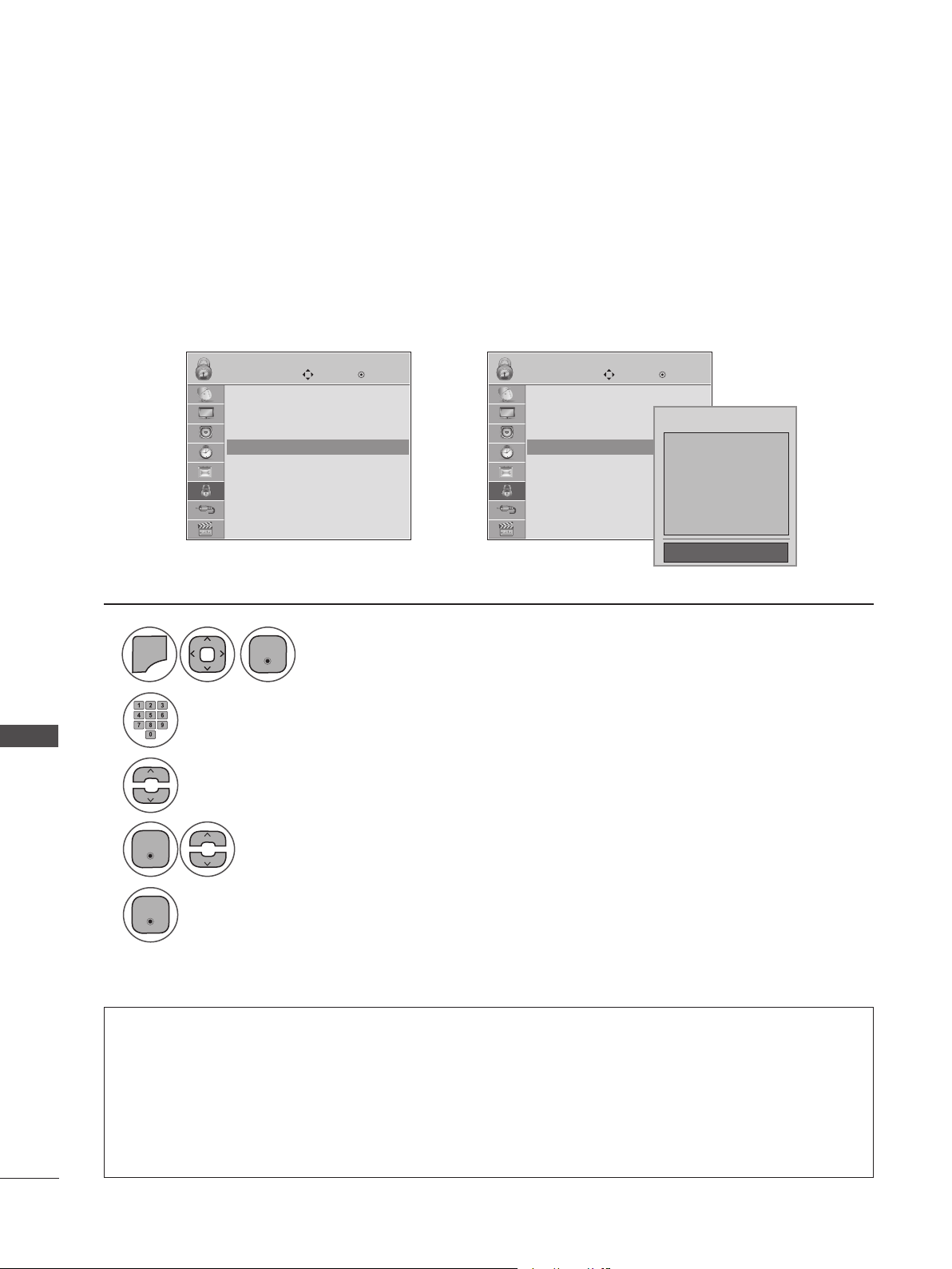
PARENTAL CONTROL/RATINGS
MOVIE & TV RATINGS
Movie Rating (MPAA) - For USA/MEXICO
Movies can be blocked according to the movie ratings limits specified, so children cannot view certain
movies. You can set the ratings limit by blocking out all the movies with the ratings above a specified
level. Keep in mind that the movie ratings limit only applies to movies shown on TV, not TV programs,
such as soap operas.
LOCK LOCK
Lock System : Off
Set Password
Block Channel
Movie Rating
Movie Rating
TV Rating-Children
TV Rating-General
Downloadable Rating
Input Block
1
MENU
Enter
Move MoveEnter Enter
Lock System : Off
Set Password
Block Channel
ꔋ
➩
Movie Rating
ꔋ
Movie Rating
TV Rating-Children
TV Rating-General
Downloadable Rating
Input Block
Select LOCK.
Blocking off : Permits all programs
G
PG
PG-13
R
NC-17
X
Blocking Off ꔗ
2
Input the password.
PARENTAL CONTROL/RATINGS
3
Select Movie Rating.
4
Enter
Select G, PG, PG-13, R, NC-17, X, or Blocking Off.
86
5
Enter
• Press MENU or EXIT to close the menu window.
• Press BACK to move to the previous menu screaen.
• G (General audiences)
• PG (Parental guidance suggested)
• PG-13 (Parents strongly cautioned)
• R (Restricted)
• NC-17 (No one 17 and under admitted)
• X (Adult only)
• Blocking Off (Permits all programs)
• If you set PG-13: G and PG movies will be available, PG-13, R, NC-17 and X will be blocked.
• If a Movie Rating is locked, enter the password to unlock it temporarily.
Page 87
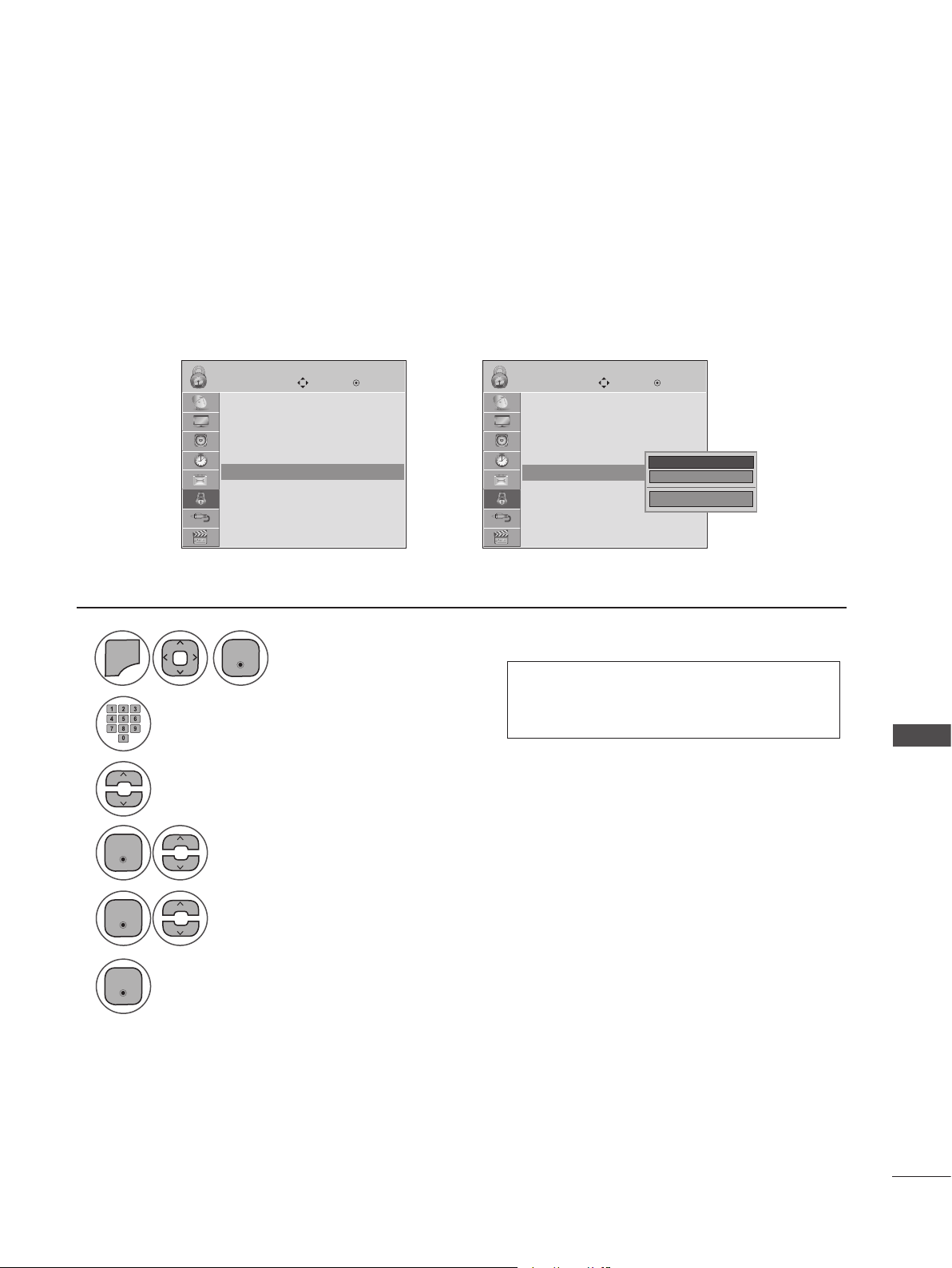
TV Ratings Children - For USA/MEXICO
Certain children's programs can be blocked according to the ratings limit set. The children rating does
not apply to other TV programs. Unless you block certain TV programs intended for mature audiences
in the TV Rating - sub menu, your children can still view these programs.
1
2
3
4
MENU
Enter
LOCK LOCK
Lock System : Off
Set Password
Block Channel
Movie Rating
TV Rating-Children ꔋ
TV Rating-Children
TV Rating-General
Downloadable Rating
Input Block
Enter
Move MoveEnter Enter
Select LOCK.
Input the password.
Select TV Rating-Children.
Select Age or Fantasy Violence.
➩
Lock System : Off
Set Password
Block Channel
Movie Rating
TV Rating-Children ꔋ
TV Rating-Children
TV Rating-General
Downloadable Rating
Input Block
Age ꔋ
Fantasy Violence
Close
• Age (applies to TV-Y, TV-Y7)
• Fantasy violence (applies to TV-Y7)
PARENTAL CONTROL/RATINGS
5
6
Enter
Enter
Select block options.
• Press MENU or EXIT to close the menu window.
• Press BACK to move to the previous menu screaen.
87
Page 88
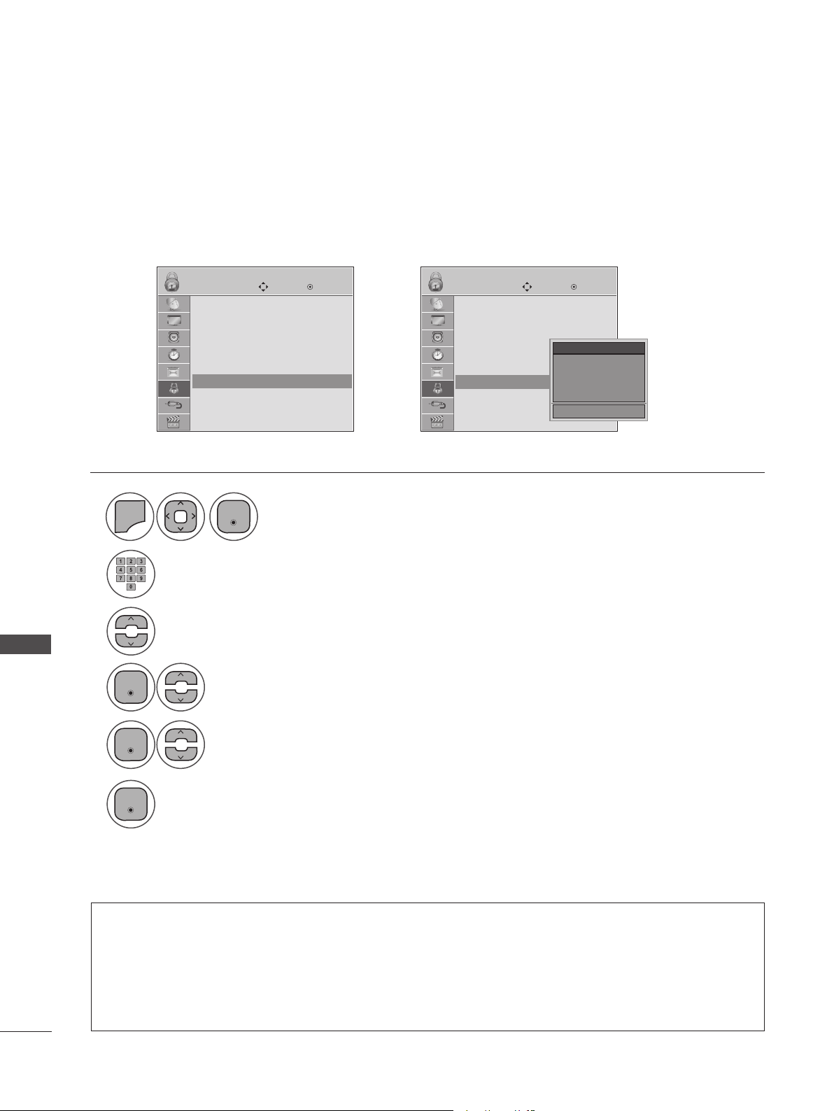
PARENTAL CONTROL/RATINGS
TV Ratings General - For USA/MEXICO
Based on the ratings, blocks certain TV programs that you and your family do not want to view.
LOCK LOCK
Lock System : Off
Set Password
Block Channel
Movie Rating
TV Rating-Children
TV Rating-General ꔋ
TV Rating-General
Downloadable Rating
Input Block
1
MENU
Enter
Move MoveEnter Enter
Lock System : Off
Set Password
➩
Block Channel
Movie Rating
TV Rating-Children
TV Rating-General ꔋ
TV Rating-General
Downloadable Rating
Input Block
Age ꔋ
Dialogue
Language
Sex
Violence
Select LOCK.
Close
2
Input the password.
3
Select TV Rating-General.
PARENTAL CONTROL/RATINGS
4
Enter
Select Age, Dialogue, Language, Sex or Violence.
88
5
Enter
Select block options.
6
Enter
• Press MENU or EXIT to close the menu window.
• Press BACK to move to the previous menu screaen.
• Age (applies to TV-G,TV-PG,TV-14,TV-MA)
• Dialogue-sexual dialogue (applies to TV-PG, TV-14)
• Language-adult language (applies to TV-PG, TV-14, TV-MA)
• Sex-sexual situations (applies to TV-PG, TV-14, TV-MA)
• Violence (applies to TV-PG, TV-14, TV-MA)
Page 89

TV Ratings English - For CANADA
Selecting Canadian English rating system.
1
2
3
4
MENU
Enter
LOCK LOCK
Lock System : Off
Set Password
Block Channel
TV Rating-English ꔋ
TV Rating-English
TV Rating-French
Downloadable Rating
Input Block
Enter
Move MoveEnter Enter
➩
Select LOCK.
Input the password.
Select TV Rating-English.
Select E, C, C8+, G, PG, 14+, 18+, or Blocking Off.
Lock System : Off
Set Password
Block Channel
TV Rating-English
TV Rating-English ꔋ
TV Rating-French
Downloadable Rating
Input Block
Blocking off : Permits all programs
E
C
C8+
G
PG
14+
18+
Blocking Off ꔗ
PARENTAL CONTROL/RATINGS
5
Enter
• Press MENU or EXIT to close the menu window.
• Press BACK to move to the previous menu screaen.
• If TV Rating-English or TV Rating-French is locked, enter the password to unlock it temporarily.
• E (Exempt)
• C (Children)
• C8+ (Children eight years and older)
• G (General programming, suitable for all audiences)
• PG (Parental Guidance)
• 14+ (Viewers 14 years and older)
• 18+ (Adult programming)
• Blocking Off (Permits all programs)
89
Page 90

PARENTAL CONTROL/RATINGS
TV Ratings French - For CANADA
Selecting Canadian French rating system.
LOCK LOCK
Lock System : Off
Set Password
Block Channel
TV Rating-English
TV Rating-French ꔋ
TV Rating-French
Downloadable Rating
Input Block
1
MENU
Enter
Move MoveEnter Enter
Lock System : Off
➩
Set Password
Block Channel
TV Rating-English
TV Rating-French ꔋ
TV Rating-French
Downloadable Rating
Input Block
Blocking off : Permits all programs
Select LOCK.
E
G
8ans+
13ans+
16ans+
18ans+
Blocking Off ꔗ
2
Input the password.
3
Select TV Rating-French.
PARENTAL CONTROL/RATINGS
4
Enter
Select E, G, 8ans+, 13ans+, 16ans+, 18ans+, or Blocking off.
90
5
Enter
• Press MENU or EXIT to close the menu window.
• Press BACK to move to the previous menu screaen.
• E (Exempt)
• C (Children)
• C8+ (General-not suitable for little children)
• 13ans+ (Not suitable for children of 13 years and younger)
• 16ans+ (Not suitable for children of 16 years and younger)
• 18ans+ (These programs are only for adults)
• Blocking Off (Permits all programs)
Page 91

DOWNLOADABLE RATINGS
Downloadable ratings are only available for digital channels and operate only when TV has received
Region 5 rating data
2
3
LOCK LOCK
Lock System : Off
Set Password
Block Channel
Movie Rating
TV Rating-Children
TV Rating-General
Downloadable Rating ꔋ
Downloadable Rating
Input Block
Move MoveEnter Enter
Lock System : Off
➩
Set Password
Block Channel
Movie Rating
TV Rating-Children
TV Rating-General
Downloadable Rating ꔋ
Downloadable Rating
Input Block
Humor
Sport
Cruelty
Language
Sadness
Genre
Age
Close
• Based on ratings tables, your TV's OSD
(On-Screen Display) may differ slightly
from what is shown in this manual.
1
MENU
Enter
Select LOCK.
• If a downloadable rating is locked, enter
the password to unlock it temporarily.
Input the password.
PARENTAL CONTROL/RATINGS
Select Downloadable Rating.
4
5
6
Enter
Enter
Enter
Select Downloadable Rating option.
Select desired option and block it.
• Press MENU or EXIT to close the menu window.
• Press BACK to move to the previous menu screaen.
91
Page 92

PARENTAL CONTROL/RATINGS
EXTERNAL INPUT BLOCKING
Enables you to block an input.
LOCK LOCK
Lock System : Off
Set Password
Block Channel
Movie Rating
TV Rating-Children
TV Rating-General
Downloadable Rating
Input Block ꔋ
Input Block
1
MENU
Enter
Move MoveEnter Enter
Lock System : Off
Set Password
Block Channel
➩
Movie Rating
TV Rating-Children
TV Rating-General
Downloadable Rating
Input Block ꔋ
Input Block
Select LOCK.
AV
Component
RGB-PC
HDMI1
HDMI2
◄ Off ►
Off
Off
Off
Off
Close
2
Input the password.
PARENTAL CONTROL/RATINGS
3
Select Input Block.
92
4
5
6
Enter
Select On or Off.
Enter
Select input source.
• Press MENU or EXIT to close the menu window.
• Press BACK to move to the previous menu screaen.
Page 93

USING USB DEVICES
USB IN
ENTRY MODES
When you connect a USB device, this pop-up menu is displayed automatically. If the pop-up menu
does not appear, you can manually select Photo List, Music List or Movie List in the USB menu. On a
USB device, you cannot add new folders or delete an existing folders.
Connect the USB device to the USB jack on
1
the back of the SET.
• This set supports JPG, MP3 and HD DivX file
types.
2
Select PHOTO LIST, MUSIC LIST or MOVIE LIST.
PHOTO LIST
MUSIC LIST
MOVIE LIST
3
Enter
Removing USB Devices
Select the USB device menu before removing the USB device.
1
Select USB Device.
2
Enter
Select Eject.
USING USB DEVICES
93
Page 94

USING USB DEVICES
USB Device Precautions
►Only a USB storage device is recognizable.
►If the USB storage device is connected through a USB hub, the device is not recognizable.
►A USB storage device using an automatic recognition program may not be recognized.
►A USB storage device that uses its own driver may not be recognized.
►The recognition speed of a USB storage device may depend on each device.
►Please do not turn off the MONITOR or unplug the USB device when the connected USB storage
device is working. When such device is suddenly separated or unplugged, the stored files or the
USB storage device may be damaged.
►Do not connect a USB storage device that has been artificially written to on the PC. The device
may cause the monitor to malfunction or fail to be played. Never forget to use only a USB storage
device that has normal music files or image files.
►Please use only a USB storage device that was formatted as a FAT16, FAT32, NTFS file system
provided with the Windows operating system. If a storage device has been formatted as a different
utility program that is not supported by Windows, it may not be recognized. Data on a USB storage
device cannot be deleted in the NTFS file system.
►Please connect power to a USB storage device that requires an external power supply. If not, the
device may not be recognized.
►Please connect a USB storage device with the cable provided by the USB maker. If connected with
an aftermarket cable or an excessively long cable, the device may not be recognized.
►Some USB storage devices may not be supported or operate smoothly.
►A maximum of 999 files and folders can be recognized.
►Data on a USB storage device cannot be aligned. Up to 128 English characters can be recognized
as a file name.
►Please back up important files because data on the USB device may be damaged. Data manage-
ment is solely the consumer's responsibility and the manufacturer does not cover the product
bearing data damage.
USING USB DEVICES
►If the USB is connected in Standby Mode, the device will automatically be loaded when the mon-
itor is turned on.
►The recommended capacity is 1TB or less for an external USB hard disk and 32GB or less for USB
memory.
►Any device with more than the recommended capacity may not work properly.
►If an external USB hard disk with a “Power Saving” function does not work, turn the hard disk off
and on again to make it work properly.
►USB storage devices below USB 2.0 are supported, but they may not work properly in the movie
list.
►When using a USB HDD via a USB extension cable, connect it to a supported power source.
94
Page 95

PHOTO LIST
You can only view .JPG files from USB storage devices. The on-Screen display on your model may be
slightly different.
Supported photo file type: *.JPG
• You can view JPG files only.
• Only baseline scan JPGs are supported.
• Available JPG file size: 64 pixel (width) x 64 pixel (height) to 15360 pixel (width) x 8640 pixel
(height)
Screen Components
1
MENU
Moves to upper level folder
1
Preview: Displays the thumbnail/
2
folder name of the photo in the
selected folder
Current page/total pages
3
Total number of marked photos.
4
Corresponding buttons on the
5
remote control.
Select USB.
2
Enter Enter
3
Photo List
Drive1
SGKIM001
2
1366x768, 125KB
1
Up Folder
Page 2/3
Up Folder
SG101 04/01/2010
SG102 04/01/2010
SGKIM001 04/01/2010
SGKIM002 04/01/2010
SGKIM003 04/01/2010
SGKIM004 04/01/2010
Popup MenuNavigation MarkPage Change Exit
5
Select Photo List.
4
USING USB DEVICES
No Marked
SG103 04/01/2010
SG104 04/01/2010
SGKIM005 04/01/2010
SGKIM007 04/01/2010
SGKIM008 04/01/2010
SGKIM009 04/01/2010
SGKIM010 04/01/2010
MARK
95
Page 96

USING USB DEVICES
Photo Selection and Pop-up Menu
Photo List
Drive1
SGKIM001
1366x768, 125KB
Up Folder
Popup MenuNavigation MarkPage Change Exit
No Marked
Page 2/3
Up Folder
SG101 04/01/2010
SG102 04/01/2010
SGKIM001 04/01/2010
SGKIM002 04/01/2010
SGKIM003 04/01/2010
SGKIM004 04/01/2010
SG103 04/01/2010
SG104 04/01/2010
SGKIM005 04/01/2010
SGKIM007 04/01/2010
SGKIM008 04/01/2010
SGKIM009 04/01/2010
SGKIM010 04/01/2010
MARK
➩
When you select a file (not folder), this Pop-up menu
Photo List
Drive1
SGKIM001
1366x768, 125KB
Up Folder
Popup MenuNavigation MarkPage Change Exit
No Marked
Page 2/3
Up Folder
SG101 04/01/2010
SG102 04/01/2010
SGKIM001 04/01/2010
SGKIM002 04/01/2010
SGKIM003 04/01/2010
SGKIM004 04/01/2010
SG103 04/01/2010
SG104 04/01/2010
SGKIM005 04/01/2010
SGKIM007 04/01/2010
SGKIM008 04/01/2010
SGKIM009 04/01/2010
SGKIM010 04/01/2010
MARK
1366x768, 125KB
View ꔋ
Mark All
Delete
Close
is displayed.
► View: Display the selected item.
► Mark All: Mark all photos on the screen.
► Unmark All: Deselect all marked photos.
► Delete or Delete Marked: Delete the selected photo item.
► Close: Close the Pop-up menu.
1
Select the target folder or drive.
2
Enter
USING USB DEVICES
3
Enter
Show the Pop-up menu.
Select the desired photos.
4
Enter
Select the desired Pop-up menu.
• Use CH ꕭꕮ to navigate in the photo
page.
• Use MARK to mark or unmark a photo.
When one or more photos are marked,
you can view individual photos or a slide
show of the marked photos. If no photos
are marked, you can view all photos individually or all photos in the folder in a
slide show.
96
• Press BACK to move to the previous menu screen.
Page 97

Full Screen Menu
You can change the Photo List view so that it fills the screen. More operations are available in full
screen mode.
2
Photo List
Drive1
SGKIM001
1366x768, 125KB
Up Folder
Popup MenuNavigation MarkPage Change Exit
No Marked
Page 2/3
Up Folder
SG101 04/01/2010
SG102 04/01/2010
SGKIM001 04/01/2010
SGKIM002 04/01/2010
SGKIM003 04/01/2010
SGKIM004 04/01/2010
SG103 04/01/2010
SG104 04/01/2010
SGKIM005 04/01/2010
SGKIM007 04/01/2010
SGKIM008 04/01/2010
SGKIM009 04/01/2010
SGKIM010 04/01/2010
MARK
➩
Photo List
Drive1
SGKIM001
1366x768, 125KB
Up Folder
Popup MenuNavigation MarkPage Change Exit
No Marked
Page 2/3
Up Folder
SG101 04/01/2010
SG102 04/01/2010
SGKIM001 04/01/2010
SGKIM002 04/01/2010
SGKIM003 04/01/2010
SGKIM004 04/01/2010
SG103 04/01/2010
SG104 04/01/2010
SGKIM005 04/01/2010
SGKIM007 04/01/2010
SGKIM008 04/01/2010
SGKIM009 04/01/2010
SGKIM010 04/01/2010
MARK
1366x768, 125KB
View ꔋ
Mark All
Delete
Close
➩
◄ 1/17 ►
Slideshow ꘡ BGM ꘡
꘤
Delete Option Hide
The aspect ratio of a photo may change the
size of the photo displayed on the screen in full
size. Press BACK to move to the previous
menu screen.
1
Enter
Select the target folder or drive.
Select the desired photos.
• Use CH ꕭꕮ to navigation in the photo
page.
USING USB DEVICES
3
4
5
Enter
Enter
Show the Pop-up menu.
Select View.
The selected photo is displayed in full size.
• Press BACK to move to the previous menu screen.
97
Page 98

USING USB DEVICES
6
◄ 1/17 ►
Slideshow ꘡ BGM ꘡
꘤
Delete Option Hide
► Slideshow : Selected photos are displayed during the slide show. If no
photo is selected, all photos in the current folder are displayed during
slide show.
■ Set the time interval of the slide show in Option.
► BGM: Listen to music while viewing photos in full-size..
■ Set the BGM device and album in Option.
• Use < > to select the previous or next
photo.
• Use ꕭꕮ< > to select and control the menu
on the full-sized screen.
Select the Slideshow , BGM,
꘤(Rotate), Delete , Option or Hide.
98
► ꘤
(Rotate): Rotate photos.
USING USB DEVICES
■ Rotates the photo 90°, 180°, 270°, 360° clockwise.
► Delete: Delete photos.
► Option: Set values for Slide Speed and Music Album.
■ Use ꕭꕮ < > and ENTER to set values Then go to
and press ENTER to save the settings.
Press ◀▶ to set the time interval between slides.
Slide Speed
Music aalbum
Enter
Enter Cancel
Fast
...
■ You cannot change the Music Album while BGM is playing.
► Hide: Hide the menu on the full-sized screen.
■ To see the menu again on the full-sized screen, press
ENTER to display.
Page 99

MUSIC LIST
You can use the Music List menu to play MP3 files from a USB storage device. This set cannot play back
copy-protected files. The on-screen display on your model may be slightly different.
Supported music file type: *.MP3
Bit rate range 32 kbps to 320 kbps
• Sampling rate MPEG1 Layer3: 32kHz, 44.1kHz, 48kHz
• Sampling rate MPEG2 Layer3: 16kHz, 22.05kHz, 24kHz
• Sampling rate MPEG2.5 Layer3: 8kHz, 11.025kHz, 12kHz
Screen Components
1
MENU
Moves to upper level folder
1
Preview: If any album jacket for
2
the file exists, this jacket is dis-
played
Current page/total pages
3
4
Total number of marked music
files
Corresponding buttons on the
5
remote control
Select USB.
2
Enter Enter
3 4
Music List
2
1
Music
SGKIM003
00:00/01:34
Up Folder
Page 2/3
Popup MenuNavigation Mark ExitPage Change
5
Select Music List.
No Marked
Title Duration
Up Folder
SGKIM001
SGKIM002
SGKIM003
SGKIM004
SGKIM005
USING USB DEVICES
03:33
04:45
01:30
02:37
01:58
MARK
99
Page 100

USING USB DEVICES
Music Selection and Pop-up Menu
Music List
Music
SGKIM003
00:00/01:34
Page 2/3
Up Folder
Popup MenuNavigation Mark ExitPage Change
No Marked
Title Duration
Up Folder
SGKIM001
SGKIM002
SGKIM003
SGKIM004
SGKIM005
➩
Once a song finishes playing, the next selected
03:33
04:45
01:30
02:37
01:58
MARK
one will be played. When there are no selected
files to play, the next one in the current folder
will be played. If you go to a different folder and
press ENTER, the current song in playback will
stop.
► Play Marked: Plays the selected files. Once a file
finishes playing, the next selected one will be played
automatically.
► Stop Play (During playback): Stop the playing files.
► Play (During stop): Plays the selected music titles.
Music List
Music
SGKIM003
00:00/01:34
Page 2/3
Up Folder
Popup MenuNavigation Mark ExitPage Change
No Marked
Title Duration
Up Folder
SGKIM001
SGKIM002
SGKIM003
SGKIM004
SGKIM005
MARK
3945 KB 128 Kbps
03:33
Play ꔋ
Play with Photo
04:45
Mark All
01:30
Delete
Close
02:37
01:58
► Play with Photo: Starts playing the selected files and
then move to the Photo List..
► Mark All: Marks all files in the folder.
► Unmark All: Deselects all marked files.
► Delete or Delete Marked: Deletes the selected files.
► Close: Close the
Pop-up
menu.
1
Select the target folder or drive.
2
USING USB DEVICES
Enter
Select the desired music files.
3
Enter
Show the Pop-up menu.
4
Enter
Select the desired Pop-up menu.
• Use CH ꕭꕮ to navigate up/down in the
music page
• Use MARK to mark or unmark a music
file. If no music is marked, all the music
in the folder will be played in sequence.
When one or more music files are
marked, the marked music files will be
played in sequence. If you want to listen
to only one song repeatedly, just mark
that one file and play.
100
• Press BACK to move to the previous menu screen.
 Loading...