

LG M1721A-BMF.A**NLF, M1921A-BMF.A**NLF Schematic
COLOR MONITOR
SERVICE MANUAL
Website:http://biz.LGservice.com
E-mail:http://www.LGEservice.com/techsup.html
CAUTION
BEFORE SERVICING THE UNIT,
READ THE SAFETY PRECAUTIONS IN THIS MANUAL.
CHASSIS NO. : CL-81
MODEL: M1721A (M1721A-BMF.A**NLF)
M1921A (M1921A-BMF.A**NLF)
*( ) **Same model for Service
- 2 -
CONTENTS
SPECIFICATIONS
SPECIFICATIONS ................................................... 2
PRECAUTIONS ....................................................... 3
SERVICE PRECAUTIONS ...................................... 4
TIMING CHART ....................................................... 7
DISASSEMBLY ....................................................... 8
BLOCK DIAGRAM ................................................... 9
DESCRIPTION OF BLOCK DIAGRAM ................. 10
ADJUSTMENT ...................................................... 12
TROUBLESHOOTING GUIDE .............................. 16
WIRING DIAGRAM ............................................... 20
EXPLODED VIEW...................................................21
REPLACEMENT PARTS LIST ...............................23
SCHEMATIC DIAGRAM......................................... 29
1. LCD CHARACTERISTICS
Type : TFT Color LCD Module
Active Video Area : 17.0 inch-M1721A
: 19.0 inch-M1921A
Size : 358.5(V) x 296.5(H) x 17(D)-M1721A
:
396.0(V) x 324.0(H) x 16.5(D)-M1921A
Pixel Pitch :
0.264mm x 0.264mm x RGB-M1721A
:
0.098mm x RGBmm x 0.294-M1921A
Color Depth : 6Bits with FRC, 16,777,216 colors
Surface Treatment : Anti Glare, Hard Coating(3H)
Operating Mode : Normally white
Backlight Unit : 4CCFL
Electrical Interface : LVDS
2. OPTICAL CHARACTERISTICS
2-1. Viewing Angle by Contrast Ratio ≥ 10
M1721A
Left : -60° min., -70° typ Right : +60° min., +70° typ
Top : +60° min., +75° typ Bottom : -50° min., -65° typ
M1921A
Left : -70° min., -80° typ Right : +70° min., +80° typ
Top : +60° min., +70° typ Bottom : -50° min., -85° typ
2-2. Luminance : 160(min.), 250(typ.)
2-3 Contrast Ratio : 300(min.), 550(max.)-M1721A
: 350(min.), 650(max.)-M1921A
3. SIGNAL (Refer to the Timing Chart)
3-1. Analog Video Input
1) Video Input Range : 0~0.7V ± 5%
2) Video Termination Impedance : 75Ω ±5%
3) Sync Type : Separate Sync.
4) Sync Level : TTL Low ≤ 0.8V, High ≥ 2.0V
3-2. Operating Frequency
Horizontal : 30 ~ 70kHz
Vertical : 56 ~ 75Hz
4. RESOLUTION
Analog Max : 1280 x 1024@60Hz
5. POWER SUPPLY
5-1. Power
AC 100-240Vac, 50/60Hz
5-2. Power Consumption
6. ENVIRONMENT
5-1. Operating Temperature : 10°C ~ 35°C
5-2. Operating Humidity : 20% ~ 80%
5-3. MTBF : 50,000 Hours (Min)
7. DIMENSIONS (with TILT/SWIVEL)
M1721A
Width : 394.4 mm (15.53'')
Depth : 243 mm (9.57'')
Height : 404 mm (15.91'')
M1921A
Width : 445 mm (17.52'')
Depth : 243 mm (9.57'')
Height : 457 mm (17.99'')
8. WEIGHT (with TILT/SWIVEL)
M1721A
Net. Weight : 4.5 kg (9.92 lbs)
Gross Weight : 6.2 kg (14.33 lbs)
M1921A
Net. Weight : 5.5 kg (12.13 lbs)
Gross Weight : 7.1 kg (15.66 lbs)
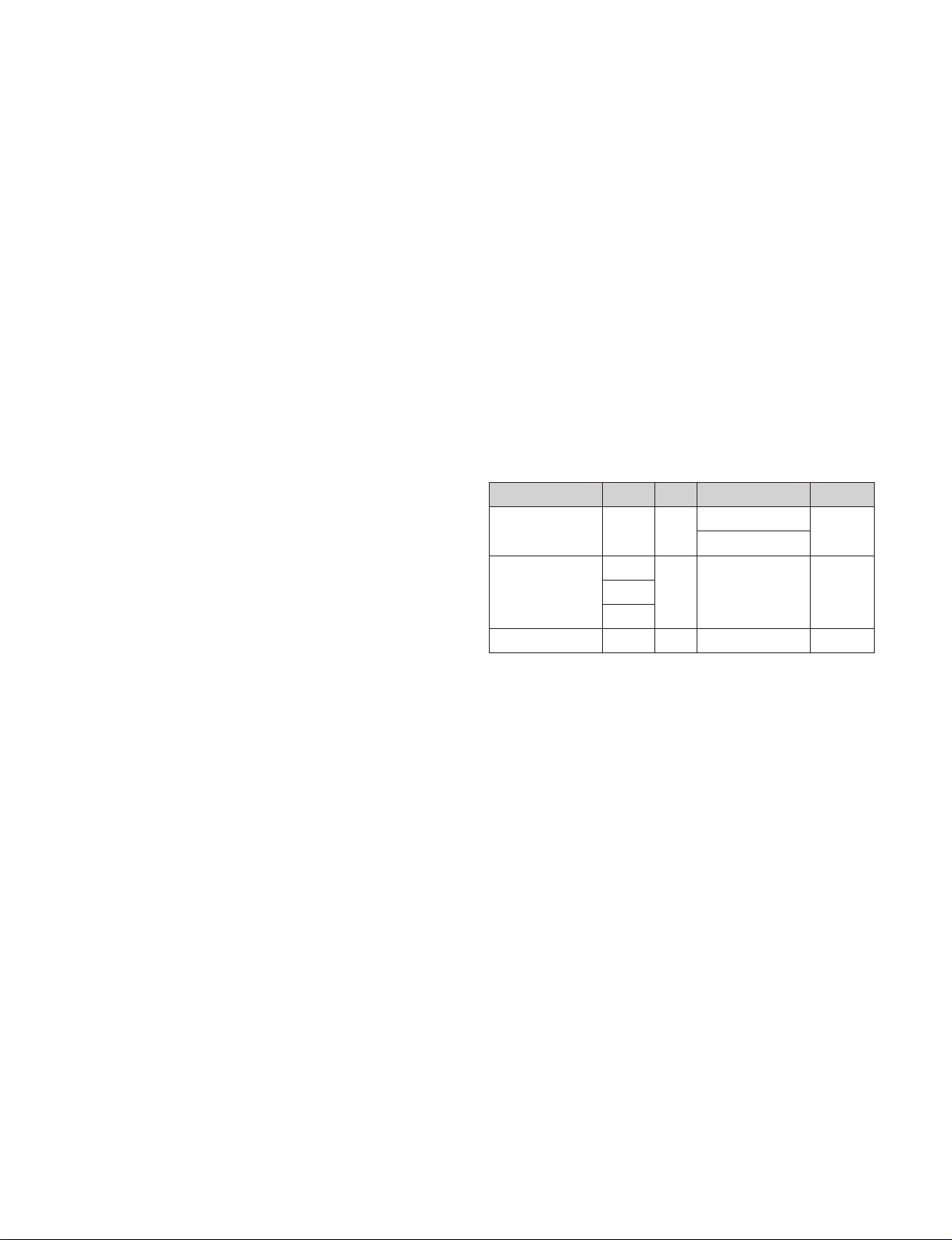
H/V SYNC
ON/ON
OFF/ON
ON/OFF
OFF/OFF
-
MODE
POWER ON (NORMAL)
SLEEP MODE
POWER S/W OFF
VIDEO
ACTIVE
OFF
OFF
POWER CONSUMPTION
less than 40 W-M1721A
less than 45 W-M1921A
less than 1 W
less than 1 W
LED COLOR
BLUE
RED
OFF
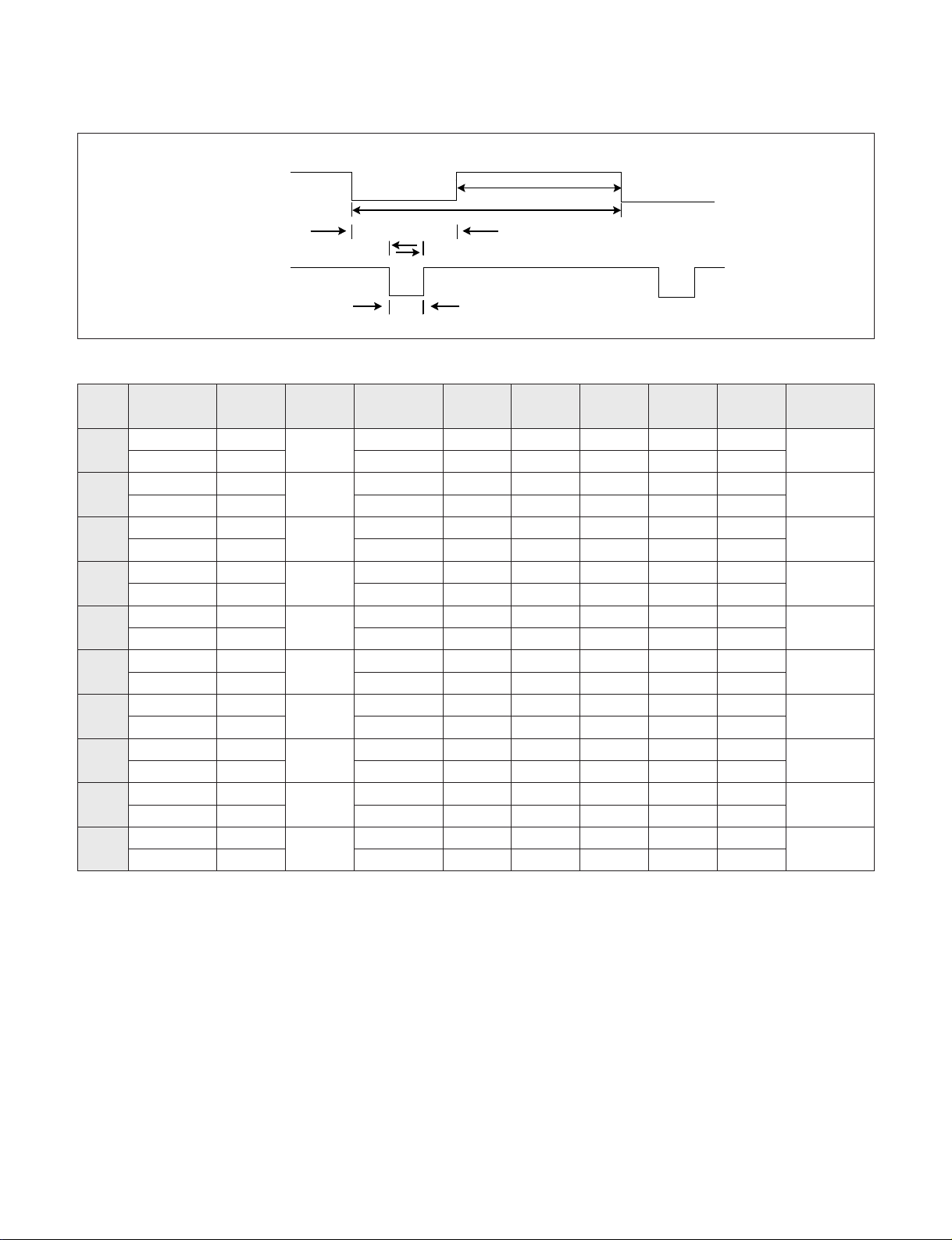
TIMING CHART
- 7 -
VIDEO
SYNC
B
C
E
A
D
1 H(Pixels) + 25.175 31.469 800 640 16 96 48 640 x 350
V(Lines) - 70.09 449 350 37 2 60
2 H(Pixels) - 28.321 31.468 900 720 18 108 54 720 X 400
V(Lines) + 70.08 449 400 12 2 35
3 H(Pixels) - 25.175 31.469 800 640 16 96 48 640 x 480
V(Lines) - 59.94 525 480 10 2 33
4 H(Pixels) - 31.5 37.5 840 640 16 64 120 640 x 480
V(Lines) - 75 500 480 1 3 16
5 H(Pixels) + 40.0 37.879 1056 800 40 128 88 800 x 600
V(Lines) + 60.317 628 600 1 4 23
6 H(Pixels) + 49.5 46.875 1056 800 16 80 160 800 x 600
V(Lines) + 75.0 625 600 1 3 21
7 H(Pixels) +/- 57.283 49.725 1152 832 32 64 224 832 x 624
V(Lines) +/- 74.55 667 624 1 3 39
8 H(Pixels) - 65.0 48.363 1344 1024 24 136 160 1024 x 768
V(Lines) - 60.0 806 768 3 6 29
9 H(Pixels) - 78.75 60.123 1312 1024 16 96 176 1024 x 768
V(Lines) - 75.029 800 768 1 3 28
10 H(Pixels) + 108.0 63.981 1688 1280 48 112 248 1280 x 1024
V(Lines) + 60.02 1066 1024 1 3 38
MODE
H / V
Sync
Polarity
Dot
Clock
Frequency
Total
Period
( E )
Video
Active
Time ( A )
Sync
Duration
( D )
Front
Porch
( C )
Blanking
Time
( B )
Resolution
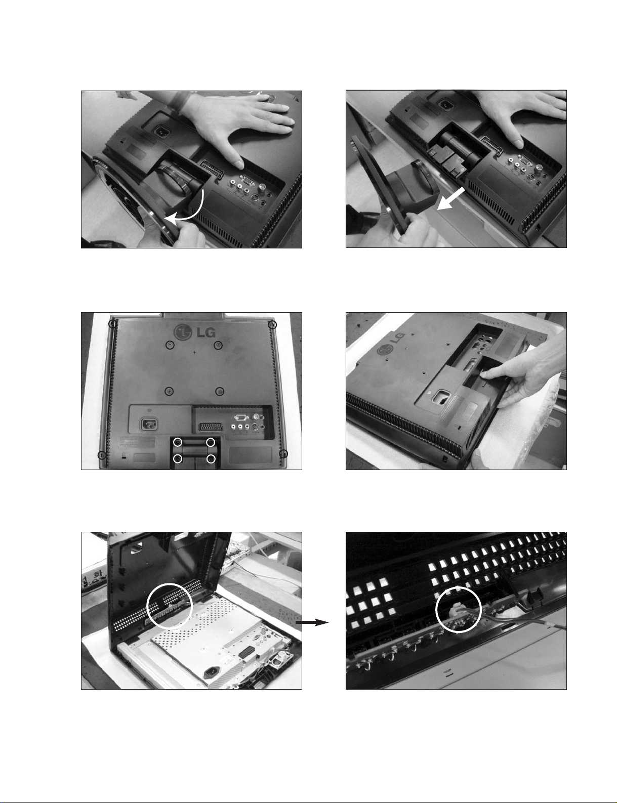
DISASSEMBLY
- 8 -
Hold the stand body & stand base.
1. Let the all latches are separated
2. Disassemble back cover.
Separate body & stand base.
Remove the screws.
# 1
# 4
# 2
# 3
Disassemble Connector.
# 5
BLOCK DIAGRAM
- 9 -
U301
U201
R/G/B Out
from UOC
30P Wafer
J103
U101
J705
5V
Option
33V
5V
J124
TN200
33V
Tuner
Pack

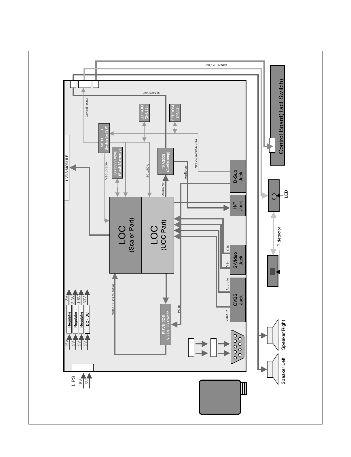
DESCRIPTION OF BLOCK DIAGRAM
- 10 -
1. Power Supply Block (LIPS)
This Block Generates DC Voltage (5V,15V) to Main Control system from AC Power (100-240V, 50/60Hz, 1.0A)
Also it has the inverter function converts input voltage to AC Rms value for the LCD lamp.
2. DC/DC Converter Block
DC/DC Converter convert the input 5V, 15V to proper 3.3V, 5V, 8V, 12V for Main control system.
For shooting heat trouble, we use the DC/DC converting IC
3. Audio Amplifier
This block is composed of TPA3005D2 and peripheral device.
The function of the audio amplifier is that to amplify audio L / R signal transmitted from audio decoder.
The audio signal is amplified according to pre-defined DC volume control curve.
4. Audio / Video / IF Decoder / Scaler
This block is composed of LOC1 and peripheral devices.
1) Video Decoder
This Block Selects input Video signals (like CVBS, Y/C) and output RGB signal.
On decoding, We can control signal like Contrast, Brightness, Sharpness, Color, Tint signals including
Adaptive Comb Filter.
2) Audio Decoder
This Block analyzes audio input signal through A/V Jack and PC audio and Tuner IF.
The analyzed signals transmitted to audio amplifier.
On decoding, We can control signal like Bass, Treble.
3) IF Decoder
This block can change IF signal to audio and video signal that transmitted to Video/Audio decoder.
4) Scaler
This IC includes A/D Converter and LVDS Transmitter.
This IC is directly inputted Analog signal and transmits it to LCD Module.
5) Micom
This block controls each IC through IIC communication line.
5. Switch IC (PI3V512QE)
It is composed of PI3V512Q.
This IC selects between D-sub RGB signal and LOC1 RGB signal, and it transmits the selected signal to
video signal processor.
6. Tuner (included Tuner Pack (TN200))
Micom controls this through IIC Line.
Tuner makes IF and transmits IF signal to LOC1.
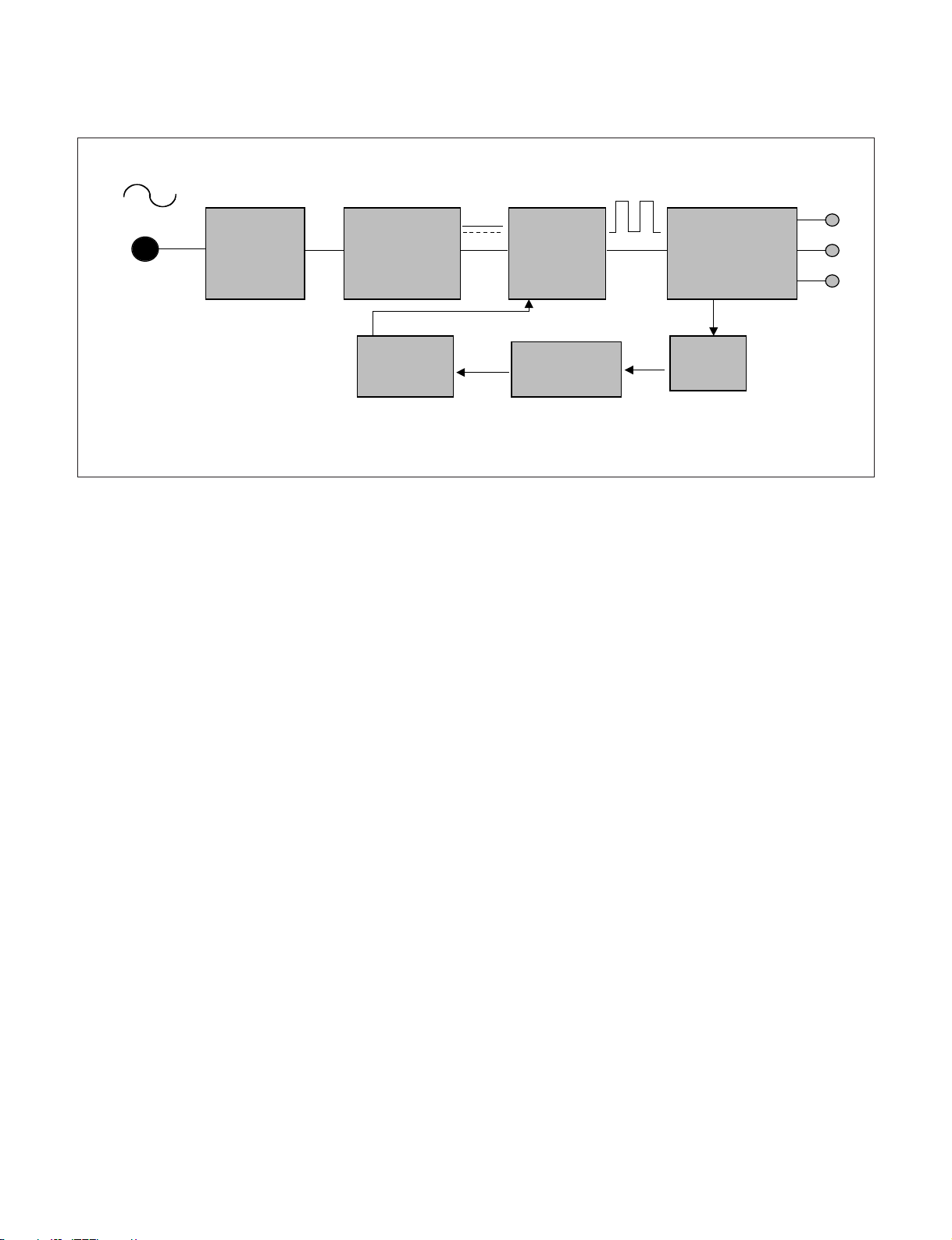
LIPS Board Block Diagram
- 11 -
Operation description_LIPS
1. EMI components.
This part contains of EMI components to comply with global marketing EMI standards like FCC, VCCI, CISPR, the
circuit included a line-filter, across line capacitor and of course the primary protection fuse.
2. Input rectifier and filter.
This part function is for transfer the input AC voltage to a DC voltage through a bridge rectifier and a bulk capacitor.
3. Energy Transfer.
This part function is for transfer the primary energy to secondary through a power transformer.
4. Output rectifier and filter.
This part function is to make a pulse with modulation control and to provide the driver signal to power switch, to adjust
the duty cycle during different AC input and output loading condition to achieve the DC output stabilized, and also the
over power protection is also monitor by this part.
5. Photo-Coupler isolation.
This part function is to feed back the DC output changing status through a photo transistor to primary controller to
achieve the stabilized DC output voltage.
6. Signal collection.
This part function is to collect the any change from the DC output and feed back to the primary through photo
transistor.
50 ~ 60Hz
LINE
100 ~ 240V
EMI
COMPONENTS
INPUT RECTIFIER
AND FILTER
PWM
COMTROL
CIRCUIT
HVDC
ENERGY
TRANSFER
PHOTO COUPLER
ISOLATION
100KHz
OUTPUT RECTIFIER
AND FILTER
SIGNAL
COLLENT-
ION
15V
5V
GND
PRIMARY SECONDARY
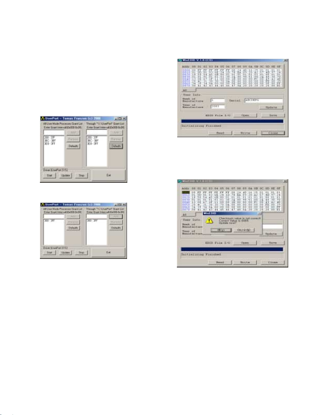
EDID ADJUSTMENT
- 12 -
Windows EDID V1.0 User Manual
Operating System: MS Windows 98, 2000, XP
Port Setup: Windows 98 => Don’t need setup
Windows 2000, XP => Need to Port Setup.
This program is available to LCD Monitor only.
1. Port Setup
a) Copy “UserPort.sys” file to
“c:\WINNT\system32\drivers” folder
b) Run Userport.exe
c) Remove all default number
d) Add 300-3FF
e) Click Start button.
f) Click Exit button.
2. EDID Read & Write
1) Run WinEDID.exe
2) Edit Week of Manufacture, Year of Manufacture,
Serial Number
a) Input User Info Data
b) Click “Update” button
c) Click “ Write” button
※※
If you don't write EDID, check below
1. Enter "SVC Menu" (refer 14page)
- Enter "Etc"
- Enter "Write Protect
1 : EDID protection (No write)
0 : EDID wirte
- Write EDID
2. Escape " SVC Menu" and push "In-stop" Button on SVC-Remote controller.
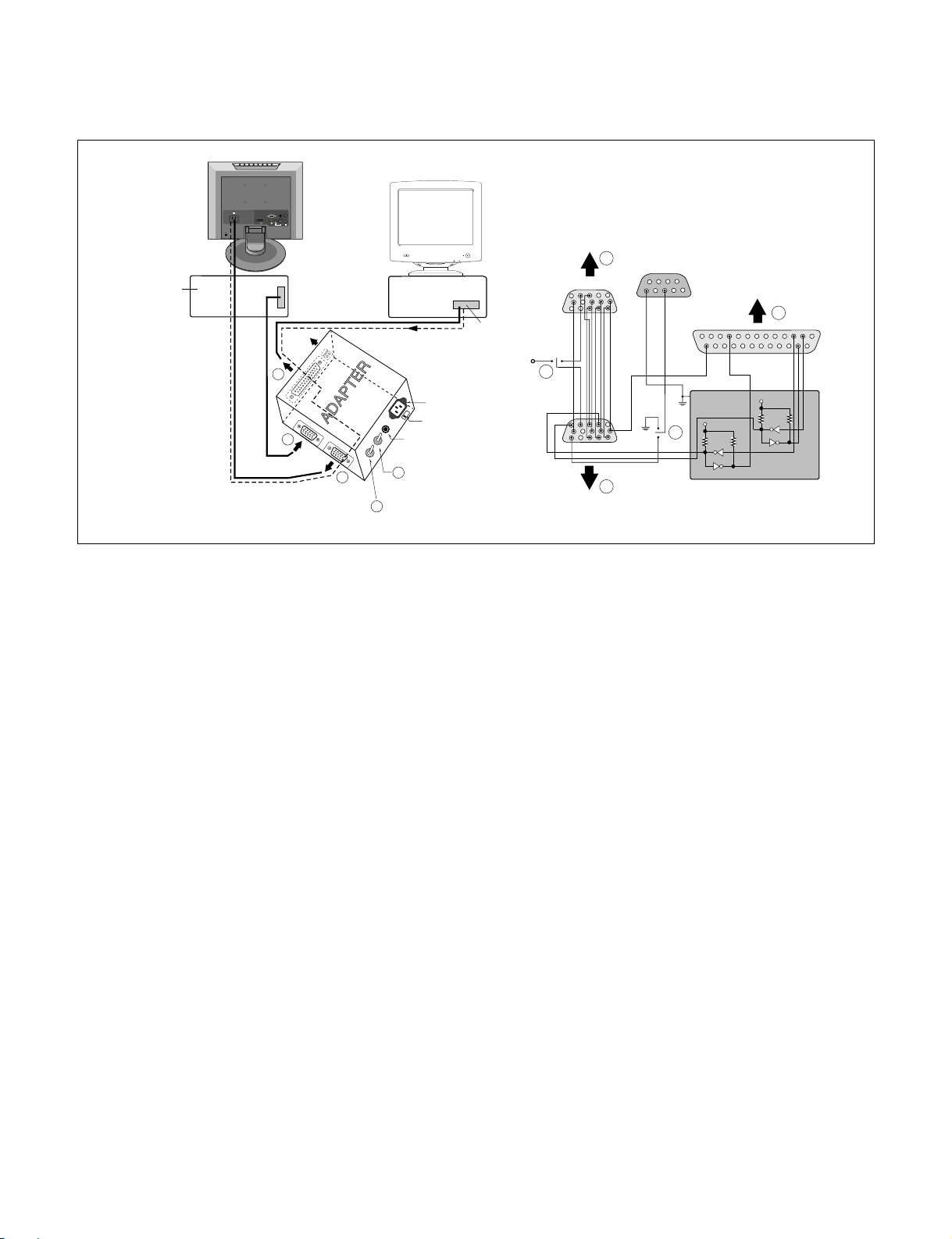
- 13 -
Video Signal
Figure 1. Cable Connection
Generator
AV1
Control Line
AUDIO
ANTENNA IN
(RGB) IN
RGB(PC/DTV) IN
AUDIO
VIDEO
LR
H/PS-VIDEO
(Mono)
AV IN 2
A
IBM
Compatible PC
15
10
5
11
6
1
PARALLEL PORT
Not used
RS232C
C
PARALLEL
Power inlet (required)
220
VGS
ST
MONITOR
A
V-SYNC
B
F
Power Select Switch
(110V/220V)
POWER
Power LED
E
ST Switch
V-Sync On/Off Switch
(Switch must be ON.)
5V
OFF ON
F
B
69
1
5
C
13
25
5V
4.7K
4.7K
74LS06
ON
OFF
5V
E
74LS06
4.7K
1
14
ADC ADJUSTMENT
- 14 -
1. DCXO setting in Video (AV2)
■ Convert to AV2 in Input-source
■ Signal equipment display
Output Voltage : 700 mVp-p
Impress Resolution : NTSC J (Model No.207 at MSPG925L)
Pattern : Color Bar (Pattern No.33 ant MSPG925L)
1) IN-START selection of Service Remote Controller
2) OPTION4 Selection
3) Right button selection in DCXO-AUTO(AV2).
Then, DCXO-AUTO may change from 0 to 1.
4) DCXO value confirmation
(Exit and Enter again Option4 _ Menu+Option4 selection)
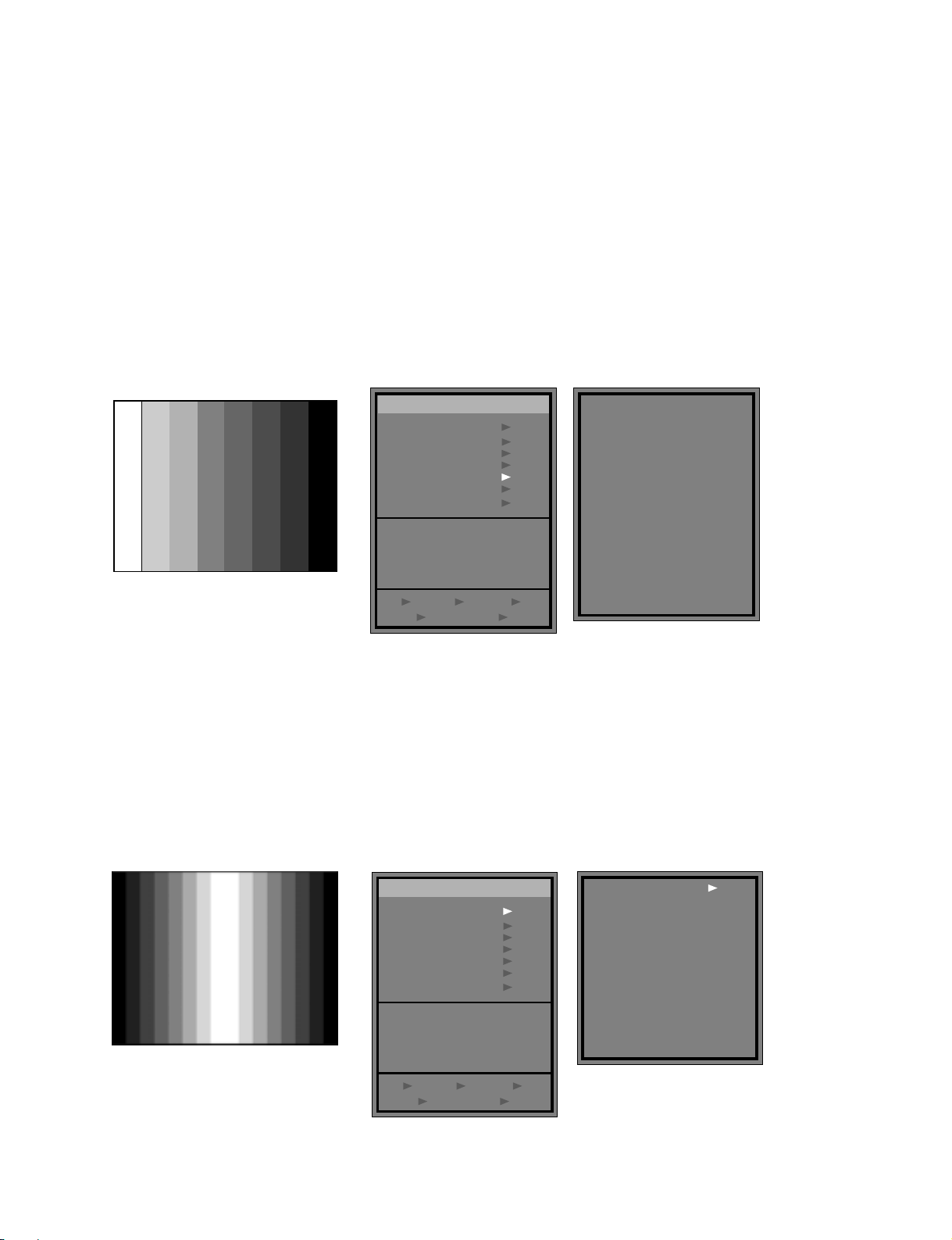
2. Video (AV2) input ADC
■ Signal equipment display
Output Voltage : 700 mVp-p
Impress Resolution : NTSC J (Model No.207 at MSPG925L)
Pattern : Gray pattern that left & right is black and center is white signal.
(Pattern No.29 ant MSPG925L)
1) IN-START selection of Service Remote Controller
2) AUTOADC Selection
3) Right button selection in Auto Gain.
Then, Value of Offset and Gain may change.
DCXO Adjustment Pattern (No.33)
Service Main Menu Option 4 Menu
(700mVp-p)
ADC Adjustment Pattern (No.29)
Service Main Menu
Auto Gain
Auto ADC
Option 1
Option 2
Option 3
Option 4
Reserved
Reset All
XXXX. XX. XX
NTSC - XX
LOC Ver XX. XX. XX
Sedna Ver XX. XX. XX
24 NG
DCXO NG BRIFE NG
Service Menu
HD NG AV NG
DCXO 60
DCXO-AUTO(AV2)
EEPROM WP
IIC-SW
BL-ADJ
UART Mssg. ON
2 Hours Off Opt.
New Sawfilter
(AUTHOR)
Sedna-Lee K.W.
UOC-Park K.W.
Option 4
Lee J.U.
Jang H.B.
Kim S.K.
195
0
1
1
0
1
1
Service Menu
Auto ADC
Option 1
Option 2
Option 3
Option 4
Reserved
Reset All
XXXX. XX. XX
NTSC - XX
LOC Ver XX. XX. XX
Sedna Ver XX. XX. XX
24 NG
DCXO NG BRIFE NG
HD NG AV NG
BRIFE
BRIFE - USA
BRIFE - KOR
Red Gain
Green Gain
Blue Gain
Red Offset
Green Offset
Blue Offset
Auto Gain
00
00
00
00
00
00
00
00
00
 Loading...