


SPECIFICATIONS
PRODUCT NAME : 2.4GHz Module for LGHA Twin washer
MODEL NAME : TWZU-V320D(LZM-001)
Designed Checked Approved
LG Innotek Co., Ltd.
Yeon
Ung
Jeong
Seok
Dong
Choi
Document No.
WC40138
2018.01.30 2018.01.30
PAGE 13
The information contained herein is the exclusive property of LG Innotek
and shall not be distributed, reproduced or disclosed in whole or no in part
without prior written permission of LG Innotek.
Specification For Approval
PAGE :
DOCUMENT No. :
REG. DATE : 2018. 01. 30
MODEL NAME : TWZU-V320D
LZM-001
REV. NO : 1.0
© 2018 LGIT. All rights reserved.
1 / 11
WC40138
REV. DATE : 2018. 01. 30
Table of Contents
No Description Page
1 Features 2
2 Ordering Information 2
3 Label Marking 2
4 Block Diagram 3
5 Absolute Maximum Ratings 3
6 Operating Test Conditions 4
7 Standard Test Conditions 4
8 Electrical Characteristics 5
9 Environmental Tests 8
10 Pin Description 9
11 Mechanical Characteristics 10
12 Outline Drawing 11
13 Packing Information 12
14 Changing History of Revision 13
Specification For Approval
PAGE :
DOCUMENT No. :
REG. DATE : 2018. 01. 30
MODEL NAME : TWZU-V320D
LZM-001
REV. NO : 1.0
© 2018 LGIT. All rights reserved.
2 / 11
WC40138
REV. DATE : 2018. 01. 30
2. Ordering Information
Model Description
TWZU-V320D
(LZM-001)
2.4GHz RF Transceiver Module
1. Features
TWZU-V320D(LZM-001) is the small size module for Twin washer.
TWZU-V320D(LZM-001) is based on Silicon Labs EFR32FG solution.
2.4GHz RF Transceiver
Size : 30mm x 43mm x 7.65 mm
PCB printed Antenna
UART interface
Applied the conformal coating
Application : Home Appliance
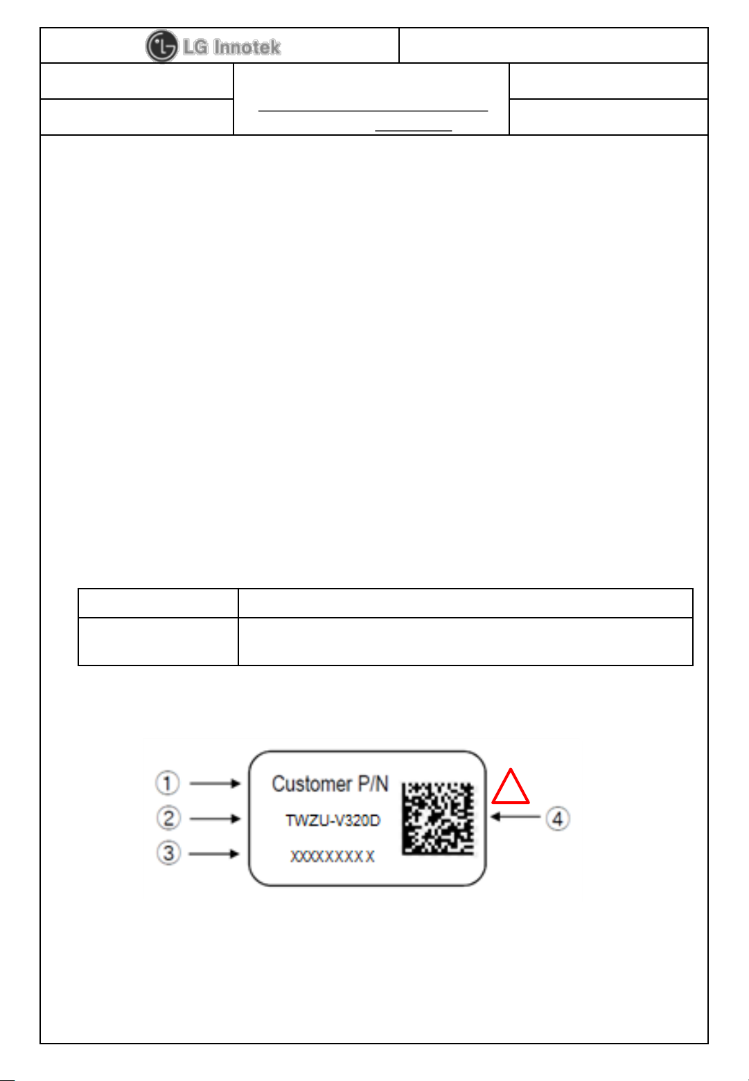
3. Label Marking
① Customer P/N EBR85871801 ③ Product Lot No. : ex) 1801A0502
② Model No. 18 : Year 05 : Date
01 : Month 02 : Manufactured Process
Revision No. : A
④ 2D Matrix Code for GMES
Contact Address : 84, Wanam-ro, Seongsan-gu, Changwon-si, Gyeongsangnam-do, 51554, Korea
Specification For Approval
PAGE :
DOCUMENT No. :
REG. DATE : 2018. 01. 30
MODEL NAME : TWZU-V320D
LZM-001
REV. NO : 1.0
© 2018 LGIT. All rights reserved.
3 / 11
WC40138
REV. DATE : 2018. 01. 30
Parameter Min Max Unit
Storage Temperature -20 +85 ℃
Storage Humidity (@ 40℃) - 90 %
Caution : The specifications above the Table define levels at which permanent damage
to the device can occur. Function operation is not guaranteed under these conditions.
Operating at absolute maximum conditions for extend periods can adversely affect the
long-term reliability of the device.
• Other conditions
1) Do not use or store modules in the corrosive atmosphere, especially where chloride
gas, sulfide gas, acid, alkali, salt or the like are contained.
Also, avoid exposure to moisture.
2) Store the modules where the temperature
and relative humidity do not exceed 5 to 40℃ and 20 to 60%.
3) Assemble the modules within 6 months.
Check the soldering ability in case of 6 months over.
5. Absolute Maximum Ratings
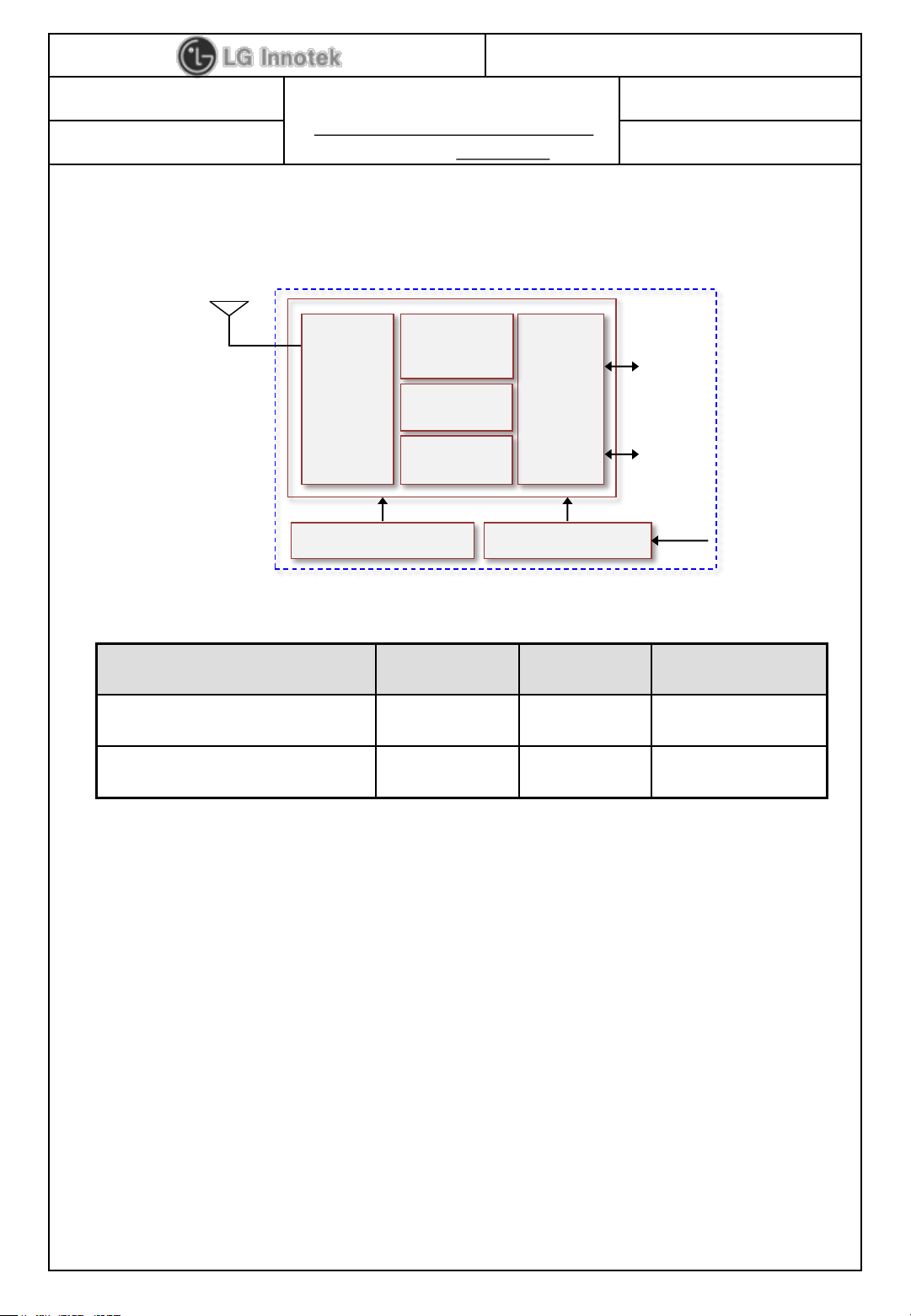
4. Block Diagram
EFR32FG
Interface
Block
CPU
(ARM-M4)
Clock(38.4MHz)
ANT
ROM 256kb
DC-DC
5V
3.3V
Radio
Transceiver
LNA, PA
BALUN
RAM 32kb
UART
JTAG

Specification For Approval
PAGE :
DOCUMENT No. :
REG. DATE : 2018. 01. 30
MODEL NAME : TWZU-V320D
LZM-001
REV. NO : 1.0
© 2018 LGIT. All rights reserved.
4 / 11
WC40138
REV. DATE : 2018. 01. 30
The Test for electrical specification shall be performed under the following condition
Otherwise this following conditions, not guaranteed this performance.
6. Operating Test Conditions
Temperature
25 ± 5℃
Humidity
65 ± 5%
Input power(VDD) Supply Voltage
+5.0V
+5.0V±10%
7. Standard Test Conditions
7-1. Ambient condition
7-2. Power supply voltages
7-3. Current consumption
Current Consumption Min. Typ. Max. Unit
TX Mode @ 6dBm - - 100
mA
RX Mode - 16 -
Human Body Model (HBM) Min. Max. Unit
Contact -
±2
kV
Air -
±10
7-4. ESD Information
Note 1 : IEC 61000-4-2 (150pF, 330R)
Parameter Min Typ Max Unit
Operating Temperature
0 - +85
℃
Operating Humidity (40℃)
- - 85
%
Supply Voltage
4.5 5.0 5.5
Vdc

DOCUMENT No. :
WC40138
REG. DATE : 2018. 01. 30
Specification For Approval
REV. NO : 1.0
MODEL NAME : TWZU-V320D
REV. DATE : 2018. 01. 30
LZM-001
PAGE :
8. Electrical Characteristics
8-1. RF Characteristics
Parameter (Condition) Min. Typ. Max. Unit
Frequency Range 2405 - 2480 MHz
TX output power
Receiver Sensitivity - -94 -90 dBm
Maximum Input Level -10 - - dBm
Frequency tolerance -30 0 +30 ppm
10.5
5 / 11
dBm
Error Vector Magnitude (EVM) - - 35 %
* Normal Condition : 25℃, VDD=5V.
* RF characteristics is board limit. It can differ according to standards
© 2018 LGIT. All rights reserved.

Specification For Approval
PAGE :
DOCUMENT No. :
REG. DATE : 2018. 01. 30
MODEL NAME : TWZU-V320D
LZM-001
REV. NO : 1.0
© 2018 LGIT. All rights reserved.
6 / 11
WC40138
REV. DATE : 2018. 01. 30
9. Environmental Tests
Item
Test Conditions SPEC
Heat Load
Test
Initial values are measured at the standard test condition.
Leave samples in 85℃±5℃ for 96±5 hours, and in standard test condition
for 30 minutes, then take measurements within 1 hour.
- Supply voltage : standard ± 5%
•TX Power
: ±4dB Max
• Min Input
Level
: ±4dB Max
Humidity
Load Test
Initial values are measured at standard test condition.
Leave samples in 85℃±5℃, 85% ±5% RH for 500 ±5 hours, and in
standard test condition for 30 minutes, then take measurements within 1 hour.
- Supply voltage : standard + 5%
Cold
Load Test
Initial values are measured at standard test condition.
Leave samples in -20℃±2℃ for 500 ±5 hours, and in the standard test
condition for 30 minutes, then take measurements within 1 hour.
- Supply voltage : standard + 5%
Cold Test
Initial values are measured at standard test condition.
Leave samples in -20℃ ±2℃ for 96 ±5 hours, and
in standard ambient for 1 hour with standard power
- Supply then take measurements within 1 hour.
Heat Test
Initial values are measured at standard test condition.
Leave samples in 85℃ ±2℃ for 96 ±5 hours, and
in standard ambient for 1 hour with standard power
- Supply then take measurements within 1 hour.
Temperature
Shock
Take measurements in standard test condition.
Temp. : -40℃ ~ +85℃ / Duration : 30 min
Ramp-up & Ramp-down for 5 min / Cycle : 300cycle.
Vibration
Test
Initial values are measured at standard test condition.
Sweep rate : 1 single sweep/minute
Acceleration : 2G / Frequency : 5-100Hz
Duration : 1 Hours per direction (X,Y,Z)
In standard condition, take measurements within 3hr.
Temp. Cycle
(Storage)
Take measurements in standard test condition.
Storage 12hours at each temperature then performed 5 cycles
-Temp. : -20℃ ~ +70℃
Input Voltage
Variation Test
Operate 3hours at each condition.
- Input voltage :±10% variation of the rated voltage

Specification For Approval
PAGE :
DOCUMENT No. :
REG. DATE : 2018. 01. 30
MODEL NAME : TWZU-V320D
LZM-001
REV. NO : 1.0
© 2018 LGIT. All rights reserved.
7 / 11
WC40138
REV. DATE : 2018. 01. 30
10. Pin Description
Pin NO Pin Name I/O Pin Description
1 UART_ Tx I/O UART Interface
2 UART_Rx I/O UART Interface
3 GND GND Ground
4 5V PWR Power
5 Wake Up I/O Wake Up
Pin #1
Pin #5

DOCUMENT No. :
WC40138
REG. DATE : 2018. 01. 30
REV. DATE : 2018. 01. 30
11. Mechanical Characteristics
11-1. Outline view
Item Test Conditions
Assembly No defects of wiring, soldering and assembling
Appearance No dirt, rust, corrosion or foreign material
11-2. Appearance structure
Item Test Conditions
Specification For Approval
MODEL NAME : TWZU-V320D
LZM-001
REV. NO : 1.0
PAGE :
8 / 11
Dimension As assembly drawing
Mounting As assembly drawing
Weight
Simplified EU Declaration of Conformity
Hereby, LG Electronic
Directive 2014/53/EU. The full text of the EU declaration of conformity is available at the following
internet address: http://www.lg.com/global/support/cedoc/cedoc#
RF Exposure
The antenna (or antennas) must be installed so as to maintain at all times a distance minimum of at
least 20 cm between the radiation source (antenna) and any individual. This device may not be
installed or used in conjunction with any other antenna or transmitter
The postal address:
s Inc. declares that the radio equipment type RF Module is in compliance with
Approximately 4.9 ± 0.5g
84, Wanam-ro, Seongsan-gu, Changwon-si, Gyeongsangnam-do, 51554, Korea
The host manufacturer has the responsibility that the host device should be compliance with all
essential requirement of RED.
© 2018 LGIT. All rights reserved.

DOCUMENT No. :
WC40138
REG. DATE : 2018. 01. 30
REV. DATE : 2018. 01. 30
12. Outline Drawing
Specification For Approval
MODEL NAME : TWZU-V320D
LZM-001
REV. NO : 1.0
PAGE :
9 / 11
© 2018 LGIT. All rights reserved.

DOCUMENT No. :
WC40138
REG. DATE : 2018. 01. 30
REV. DATE : 2018. 01. 30
13. Packing Information
Specification For Approval
MODEL NAME : TWZU-V320D
LZM-001
REV. NO : 1.0
PAGE :
10 / 11
© 2018 LGIT. All rights reserved.

DOCUMENT No. :
WC40138
REG. DATE : 2018. 01. 30
Specification For Approval
REV. NO : 1.0
MODEL NAME : TWZU-V320D
REV. DATE : 2018. 01. 30
LZM-001
PAGE :
11 / 11
14. Change History of Revision
Revision Date Contents of Revision Change Remark
1.0 ′18.01.30 First release Y. U. Jeong
© 2018 LGIT. All rights reserved.

<Regulatory notice>
1. FCC
FCC Part 15.19 Statements:
This device complies with Part 15 of the FCC Rules. Operation is subject to the following two
conditions: (1) this device may not cause harmful interference, and (2) this device must accept any
interference received, including interference that may cause undesired operation.
FCC Part 15.21 statement
Any changes or modifications not expressly approved by the party responsible for compliance could
void the user's authority to operate this equipment.
FCC Part 15.105 statement (Class B)
This equipment has been tested and found to comply with the limits for a Class B digital device,
pursuant to part 15 of the FCC Rules.
These limits are designed to provide reasonable protection against harmful interference in a
residential installation. This equipment generates, uses and can radiate radio frequency energy and,
if not installed and used in accordance with the instructions, may cause harmful interference to
radio communications. However, there is no guarantee that interference will not occur in a particular
installation. If this equipment does cause harmful interference to radio or television reception, which
can be determined by turning the equipment off and on, the user is encouraged to try to correct
the interference by one or more of the following measures:
- Reorient or relocate the receiving antenna.
- Increase the separation between the equipment and receiver.
- Connect the equipment into an outlet on a circuit different from that to which the receiver is
connected.
- Consult the dealer or an experienced radio/TV technician for help.
OEM Responsibilities to comply with FCC and Industry Canada Regulations
The module has been certified for integration into products only by OEM integrators under the
following condition:
- The antenna(s) must be installed such that a minimum separation distance of at least 20 cm is
maintained between the radiator (antenna) and all persons at all times.
- The transmitter module must not be co-located or operating in conjunction with any other antenna
or transmitter except in accordance with FCC multi-transmitter product procedures.
As long as the two condition above is met, further transmitter testing will not be required. However,
the OEM integrator is still responsible for testing their end-product for any additional compliance
requirements required with this module installed (for example, digital device emissions, PC

peripheral requirements, etc.).
End Product Labeling
The module is labeled with its own FCC ID and IC Certification Number. If the FCC ID and IC
Certification Number are not visible when the module is installed inside another device, then the
outside of the device into which the module is installed must also display a label referring to the
enclosed module. In that case, the final end product must be labeled in a visible area with the
following:
“Contains FCC ID: BEJ-LZM001”
“Contains IC: 2703N-LZM001”
2
. ISED
RS
S-GEN, Sec. 7.1.3– (licence-exempt radio apparatus)
This device complies with Industry Canada licence-exempt RSS standard(s). Operation is subject to
the following two conditions:
(1) this device may not cause interference, and
(2) this device must accept any interference, including interference that may cause undesired
operation of the device.
L
e présent appareil est conforme aux CNR d’Industrie Canada applicables aux appareils radio
exempts de licence. L’exploitation est autorisée aux deux conditions suivantes :
(1) l’appareil ne doit pas produire de brouillage, et
(2) l’utilisateur de l’appareil doit accepter tout brouillage radioélectrique subi, même si le brouillage
est susceptible d’en compromettre le fonctionnement.
F Exposure
R
The antenna (or antennas) must be installed so as to maintain at all times a distance minimum of
at least 20 cm between the radiation source (antenna) and any individual. This device may not be
installed or used in conjunction with any other antenna or transmitter.
'exposition aux RF
l
L’antenne (ou les antennes) doit être installée de façon à maintenir à tout instant une distance
minimum de au moins 20 cm entre la source de radiation (l’antenne) et toute personne physique.
aution: Any changes or modifications to this device not explicitly approved by manufacturer could
C
void your authority to operate this equipment. Attention:
es changements ou modifications de cet appareil non expressément approuvé par le fabricant
L

peuvent annuler votre droit à utiliser cet équipement.
Étiquetage du produit final (IC)
Le module BT111 est étiqueté avec sa propre identification FCC et son propre numéro de
certification IC. Si l’identification FCC et le numéro de certification IC ne sont pas visibles lorsque le
module est installé à l’intérieur d’un autre dispositif, la partie externe du dispositif dans lequel le
module est installé devra également présenter une étiquette faisant référence au module inclus.
Dans ce cas, le produit final devra être étiqueté sur une zone visible avec les informations suivantes :
« Contient module émetteur identification FCC ID: BEJ-LZM001
« Contient module émetteur IC : 2703N-LZM001”
 Loading...