

Page 1

www.lg.com
Please read this installation manual completely before installing the product.
Installation work must be performed in accordance with the national wiring
standards by authorized personnel only.
Please retain this installation manual for future reference after reading it thoroughly.
[
Representative] LG Electronics Inc. EU Representative : LG Electronics European
Shared Service Center B.V. Krijgsman 1, 1186 DM Amstelveen, The
Netherlands
[Manufacturer] LG Electronics Inc. Changwon 2nd factory 84, Wanam-ro,
Seongsan-gu, Changwon-si, Gyeongsangnam-do, KOREA
INSTALLATION MANUAL
AIR
CONDITIONER
P/NO : MFL69268904
For more information, Refer to the CD or LG Web site (www.lg.com).
VENTILATOR
Original instruction
ENGLISH ITALIANO ESPAÑOL
FRANÇAIS DEUTSCH
ΕΛΛΗΝΙΚΆ
ČEŠTINA
NEDERLANDS
POLSKI
LIMBA ROMÂNĂ
Page 2

2 Ventilator
Ventilator Installation Manual
TABLE OF CONTENTS
Safety Precaution.................3
Introduction ..........................8
Feature Dimension
Diagram...............................8
Standard drawing of installa-
tion ........................................9
Installation ..........................11
Selection of the best
location ..............................11
Ceiling dimension and hang-
ing bolt location .................12
Indoor Unit Installation.......13
Drain Piping and Water Sup-
ply Work..............................15
Check the drainage ...........16
Install the water supply
piping.................................16
Insulate all piping that
passes indoors ..................17
Duct Connection ................18
Connecting Pipes...............19
Preparation of Piping.........19
Connecting the pipings to the
indoor unit and drain hose to
drain pipe...........................20
Insulation, Others ..............20
Wiring Connection .............21
Electrical Wiring
..................21
Method to Connect Wiring
...23
Wiring for the Humidity Regu-
lator (Locally Procured) .....25
Wiring Example .................26
Installer Setting and
Test Run
...............................27
Installer setting - How to enter
installer setting mode
.........27
Installer Setting – Function
explanation ........................29
Run the humidifier .............31
In case of finding a problem at
a test run
..............................32
Airborne Noise Emission
.....32
Limiting concentration ..........32
• Screws
• Nuts
• Ceiling Fixing Bolt(M10~12)
• Washer
• Aluminium Tape
• Screws
• Screw Driver
• Spanner
• Cutter
• Cutter
• Screw Driver
Installation
Requirements
Required Parts Required Tools
Page 3
Safety Precautions
Installation Manual 3
ENGLISH
Safety Precautions
To prevent injury to the user or other people and property damage, the following instructions
must be followed.
Incorrect operation due to ignoring instruction will cause harm or damage. The seriousness is
classified by the following indications.
CAUTION
This symbol indicates the possibility of injury or damage.
Installation
Do not use a defective or underrated circuit breaker. Use this
appliance on a dedicated circuit.
• There is risk of fire or
electric shock.
For electrical work,
contact the dealer,
seller, a qualified
electrician, or an
Authorized Service
Center.
• Do not disassemble or
repair the product.
There is risk of fire or
electric shock.
Always ground the
product.
• There is risk of fire or
electric shock.
Install the panel and
the cover of control
box securely.
• There is risk of fire or
electric shock.
Always install a dedicated circuit and
breaker.
• Improper wiring or
installation may cause
fire or electric shock
Use the correctly rated
breaker or fuse.
• There is risk of fire or
electric shock.
WARNING
Do not modify or
extend the power
cable.
• There is risk of fire or
electric shock.
Do not install,
remove, or re-install
the unit by yourself
(customer).
• There is risk of fire,
electric shock, explosion, or injury.
Be cautious when
unpacking and
installing the product.
• Sharp edges could
cause injury.
Page 4

Safety Precautions
4 Ventilator
For installation, always
contact the dealer or
an Authorized Service
Center.
• There is risk of fire,
electric shock, explosion, or injury.
Do not install the
product on a defective installation
stand.
• It may cause injury,
accident, or damage to
the product.
Do not let the product
run for a long time when
the humidity is very
high and a door or a
window is left open.
• Moisture may condense
and wet or damage furniture.
Install the air intake
where polluted air
can not be directly
sucked in.
• It may cause various
accidents, including suffocation, due to the suction of harmful
gasses(CO, etc.)
Do not install this
product in a refrigerated warehouse,
heated swimming
pool or other location
where the temperature and humidity are
significantly different.
• There is risk of electrical
shock, malfunctioning.
Install this product in
an environment
where the temperature ranges from
–15°C to +45°C and
the relative humidity
is less than 80%. It
condensation is
expected to form,
heat up the fresh outside air using a duct
heater etc.
For re-installation of
the installed product,
always contact the
dealer or an Authorized Service Center.
• There is risk of fire,
electric shock, explosion
or injury.
Do not open the
maintenance cover of
the main body during
operation.
• Otherwise, it may cause
electrical shock.
Use the outdoor air
suction hole with the
net installed to
ensure that birds
could not come in.
• Remove estrange things
like the bird’s nest. Otherwise, it may cause
scarcity of indoor oxygen.
Page 5

Safety Precautions
Installation Manual 5
ENGLISH
Install this product in
and environments
where the outside air
intake meets the following conditions:
temperature range is
between –15°C and
+40°C and the relative humidity is 80%
or less.
Use the designated
electrical wires for
the terminal board
connections, and
connect the wires
securely so that they
will not become disconnected. (Failure
to ensure proper connections may cause
fire.)
When passing metal
ducts through wooden buildings clad
with metal laths, wire
laths or metal, these
ducts must be
installed in such a
way that they will not
make electrical contact with the metal
laths, wire laths or
metal sheets. (Power
leakage can cause
ignition)
Avoid fire equipment
• There is risk of fire.
When the product is
soaked (flooded or
submerged), contact
an Authorized Service
Center.
• There is risk of fire or
eletric shock.
Don't touch a dedicated circuit or breaker
with wet hands.
• There is risk of electric
shock.
Operation
When the product is
not be used for a long
time, disconnect the
power supply plug or
turn off the breaker.
• There is risk of product
damage or failure, or
unintended operation.
Do not store or use
flammable gas or
combustibles near
the product.
• There is risk of fire or
failure of product.
When flammable gas
leaks, turn off the gas
and open a window
for ventilation before
turn the product on.
• Do not use the telephone or turn switches
on or off. There is risk
of explosion or fire
Page 6
Safety Precautions
6 Ventilator
CAUTION
Don't connect the
ground wire to the window frame or water
cock.
• There is risk of electric
shock.
Do not install the product at a smoky and oily
place like kitchen or
factory.
• Otherwise. oil may
adhere to the filter or
heating exchanger and
cause trouble.
Install the product in
an insulated space
from outdoor air.
• In case of installing the
product outside of the
insulated layer, dewing
occurs inside of the
main body in winter.And
it causes electrical
shock or falling of condensed water.
Installation
Glove should be worn when doing the installation work. (There is risk of
injury.)
Be cautious that
water could not enter
the product.
• There is risk of fire,
electric shock, or product damage.
Turn the breaker off
when cleaning or
maintaining the product.
• There is risk of electric
shock.
The outside ducts
must be tilted at a
gradient (1/30 or
more) down toward
the outdoor area
from the ventilator
unit, and properly
insulated. (The entry
of rain water may
cause power leaks,
fire or damage to
household property.)
Page 7

Safety Precautions
Installation Manual 7
ENGLISH
Keep level even when
installing the product.
• To avoid vibration or
water leakage.
Use two or more people to lift and transport the product.
• Avoid personal injury.
Do not install the
product where it will
be exposed to sea
wind (salt spray)
directly.
• It may cause corrosion
on the product. Corrosion, particularly on the
condenser and evaporator fins, could cause
product malfunction or
inefficient operation.
Use a soft cloth to
clean. Do not use
harsh detergents, wax
or thinner, etc.
• Otherwise, color or surface of the oroduct mav
deteriorate.
Clean the filter and the
heat exchanger regularly and use the
gloves for cleaning.
• Adhering to a mass of
dust may cause the
deterioration of air volume.
Do not use the product for special purposes, such as preserving
foods, works of art,
etc. It is a consumer
ventilator, not a precision refrigeration system.
• There is risk of damage
or loss of property.
Operation
Do not block the inlet or outlet of
air flow.
• It may cause product failure.
Do not step on or put anyting on
the product.
• There is risk of personal injury and
failure of product.
Do not install the ventilation unit alone for controlling room temperature.
• If this is needed, install with another Indoor unit (air conditioner).
Page 8
Introduction
8 Ventilator
Introduction
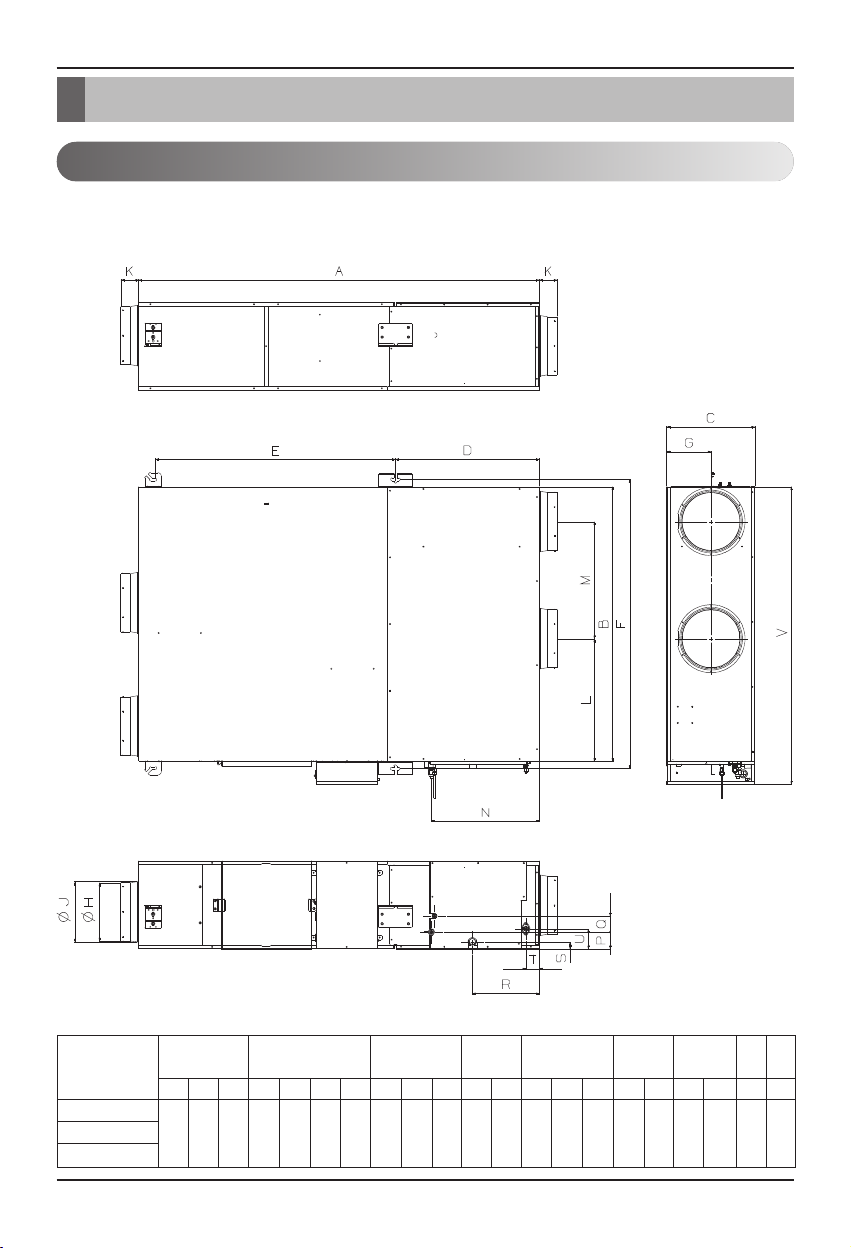
Feature Dimension Diagram
Model : LZ-H050GXN4, LZ-H080GXN4, LZ-H100GXN4
LZ-H050GXH4, LZ-H080GXH4, LZ-H100GXH4
Model
1667 1140 365 599 1006 1204 185 242 252 74 510 488 449 70 67 278 29 55 83 1239 105
ABCD EFGHJ KLMNPQRSTU Vkg
LZ-H050GXN4/LZ-H050GXH4
LZ-H080GXN4/LZ-H080GXH4
LZ-H100GXN4/LZ-H100GXH4
Figure Duct Pitch
Pipe Connec-
tion
Drain Hose
Connection
Water Supply Pip-
ing Connection
Wei-
ght
Width
Pitch of Suspension
Fixture
Duct Connection
Flange
Unit : mm
Application tools
(CMH)
Page 9
Standard drawing of installation
Installation Manual 9
ENGLISH
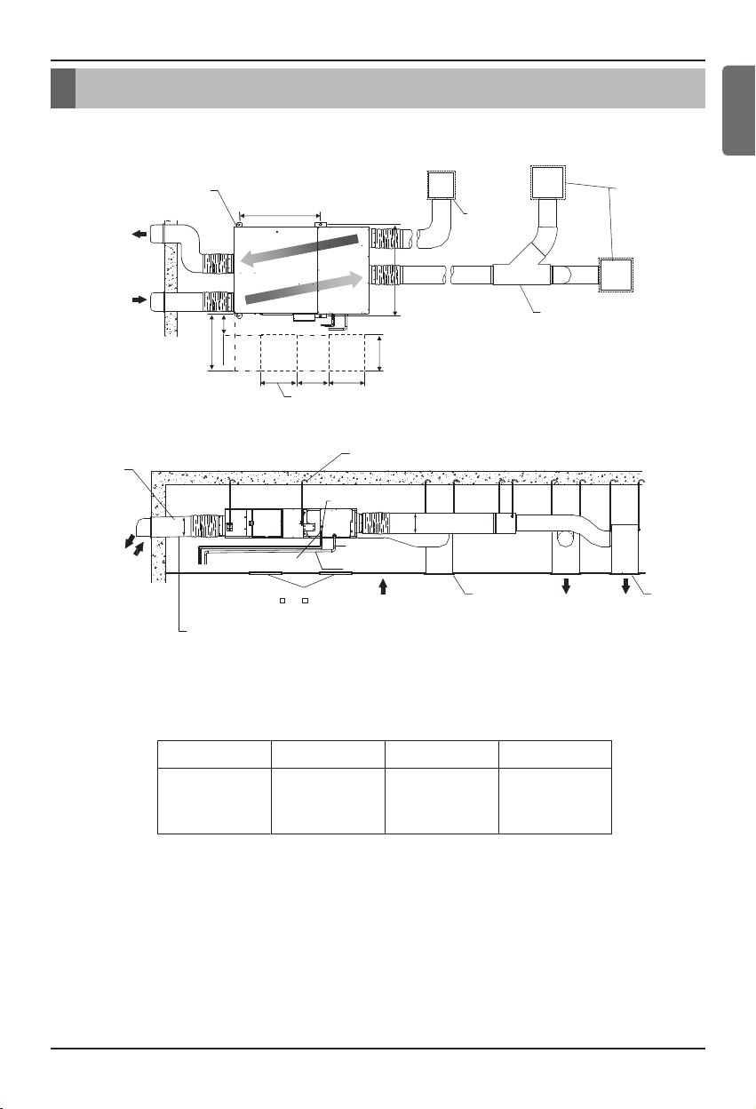
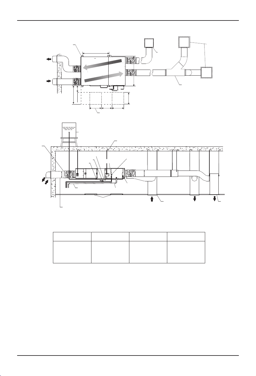
Standard drawing of installation
LZ-H050GXN4 / LZ-H080GXN4 / LZ-H100GXN4
EA
(Exaust air outlet)
OA
(Fresh air outlet)
Duct normal diameter
ØC(user-supplied)
EA
(Exaust air outlet)
(Fresh air outlet)
OA
Ceiling suspension
bolts position
More than 600
150~250
C
Refrigerant piping (Gas pipe)
(Φ12.7 Flare connection)
Duct slope: More than 1/30(toward the wall)
Obtaining of right distance
(preventing penetration of rain water)
A
B
Inspection
hatch
Inspection part
450( 600)
Inspection
hatch
600
600600
150~200
Maintenance space
Total heat Exchanger
()
Air Filter
Ceiling Fixing Bolt
(user-supplied)
Refrigerant piping
(Liquid pipe)
(Φ 6.35 Flare con
nection)
C
Drain pipe
(Inner diameter : 25.4)
Sloping downwards at a
Gradient of the 1/100
RA
(Return air)
Air return grille
(user-supplied)
Air return grille
Air supply grille
(user-supplied)
Y duct connecting
(user-supplied)
SA
(Supply air)SA(Supply air)
Air supply grille
LZ-H050GXN4
LZ-H080GXN4
LZ-H100GXN4
[Unit : mm]
CBAModel
25012041006
Page 10
Standard drawing of installation
10 Ventilator
LZ-H050GXH4 / LZ-H080GXH4 / LZ-H100GXH4
CBAModel
LZ-H050GXH4
LZ-H080GXH4
LZ-H100GXH4
[Unit : mm]
Duct slope: More than 1/30(toward the wall)
Obtaining of right distance
(preventing penetration of rain water)
Ceiling Fixing Bolt
(user-supplied)
Air supply grille
Air return grille
Inspection hatch
Duct normal diameter
ØC(user-supplied)
EA
(Exaust air outlet)
OA
(Fresh air outlet)
RA
(Return air)
SA
(Supply air)
SA
(Supply air)
C
C
Water supply
shut-off valve
(user-supplied)
Drain valve
(user-supplied)
Strainer
(user-supplied)
Refrigerant piping (Liquid pipe)
(Ø 6.35 Flare connection)
Sloping downwards at a
Drain pipe
(Inner diameter : 25.4)
Feed water pipe
(Φ6.35 Flare connection)
Gradient of the 1/100
Cistern Tank
Refrigerant piping (Gas pipe)
(Ø12.7 Flare connection)
25012041006
EA
(Exaust air outlet)
OA
(Fresh air outlet)
Ceiling suspension
bolts position
Maintenance space
Total heat Exchanger
Air Filter
Air supply grille
(user-supplied)
Air return grille
(user-supplied)
Y duct connecting
(user-supplied)
()
Inspection
hatch
Inspection
hatch
150~250
More than 600
150~200
600600
600
B
A
Page 11

Installation
Installation Manual 11
ENGLISH
Installation
Selection of the best location
Read completely, then follow step by step.
Install the ventilator in the location that satisfies the following conditions.
• The place shall easily bear a load exceeding four times the indoor unit’s weight.
• The place shall be able to inspect the unit as the figure.
• The place where the unit shall be leveled.
• The place shall allow easy water drainage.(Suitable dimension “*C” is necessary to get a slope to
drain as figure.)
• The place shall easily connect with the outdoor unit.
• The place where the unit is not affected by an electrical noise.
• The place where air circulation in the room will be good .
• There should not be any heat source or steam near the unit.
In case that the unit is installed near the sea, the installation parts may be corroded
by salt, The installation parts (and the unit) should be taken appropriate anti-corrosion measures.
CAUTION
Front view
(unit : mm)
Unit (mm)
800 or more
Maintenance
Electric parts box
space
Side view
minimum
hight
C
20 or more
Page 12

Installation
12 Ventilator
Installation of Unit
Install the unit above the ceiling correctly.
• Apply a Flexible duct between the unit and duct to absorb unnecessary vibration.
• Install the unit leaning to a drainage hole side as a figure for easy water drainage.
• A place where the unit will be leveled and that can support the weight of the unit.
• A place where the unit can withstand its vibration.
• A place where service can be easily performed.
• Avoid installing air conditioner in such circumstances where cutting oil mist or iron powder
is in suspension in factories, etc.
• Avoid places where inflammable gas is generated, flows in, is stored or vented.
• Avoid places where sulfurous acid gas or corrosive gas is generated.
• Avoid places near high frequency generators.
CASE 1
CASE 2
Ceiling dimension and hanging bolt location
POSITION OF SUSPENSION BOLT
POSITION OF CONSOLE BOLT
1006 599
Return Air(RA)
Exhaust Air(EA)
Supply Air(SA)
1204
1140
Outdoor Air(OA)
Inspection hatches
600
600
600
600
Nut
Washer
Double nut
Hanger bracket
Page 13

Installation
Installation Manual 13
ENGLISH
•
Select and mark the position for fixing bolts.
•
Drill the hole for set anchor on the face of ceiling.
• Insert the set anchor and washer onto the
suspension bolts for locking the suspension bolts on the ceiling.
• Mount the suspension bolts to the set
anchor firmly.
• Secure the installation plates onto the suspension bolts (adjust level roughly) using
nuts, washers and spring washers.
Indoor Unit Installation
Tighten the nut and bolt to prevent unit falling.
CAUTION
Old building New building
1 Set anchor
2 Plate washer
3 Spring washer
4 Nut
5 Suspension
bolts
Page 14

Installation
14 Ventilator
• Attach the hanger bracket to the suspension bolt. Be sure to fix it securely by using nuts
and washers (locally procured) from the upper and lower sides of the hanger bracket.
• Install the unit after checking the indoor (SA/RA) and outdoor (EA/OA) in accordance with
the figure duct direction label.
• Adjust the height of the unit. (Tighten the double nuts securely.)
• Check the unit is horizontally level.
• Tighten the upper nut.
• Install declination of the ventilation unit with DX coil is very important for the drain
• Minimum thickness of the insulation for the connecting pipe shall be 10mm.
CAUTION
Use a level instrument to make sure that the unit is level and that the tilt (down slope) to the drain piping connection is within 1 degree. (Refer to above figures.)
One thing to watch out for in particular is if it is installed so that the slope is not in the
Direction of the drain piping, as this might cause leaking.)
CAUTION
1 degree or less 1 degree or less
Drain hole
Horizontal line
Drain hole Duct connecting Flange
Page 15

Drain Piping and Water Supply Work
Installation Manual 15
ENGLISH
100 mm
or more
Central drain piping
(Install with a downward slope of at least 1/100)
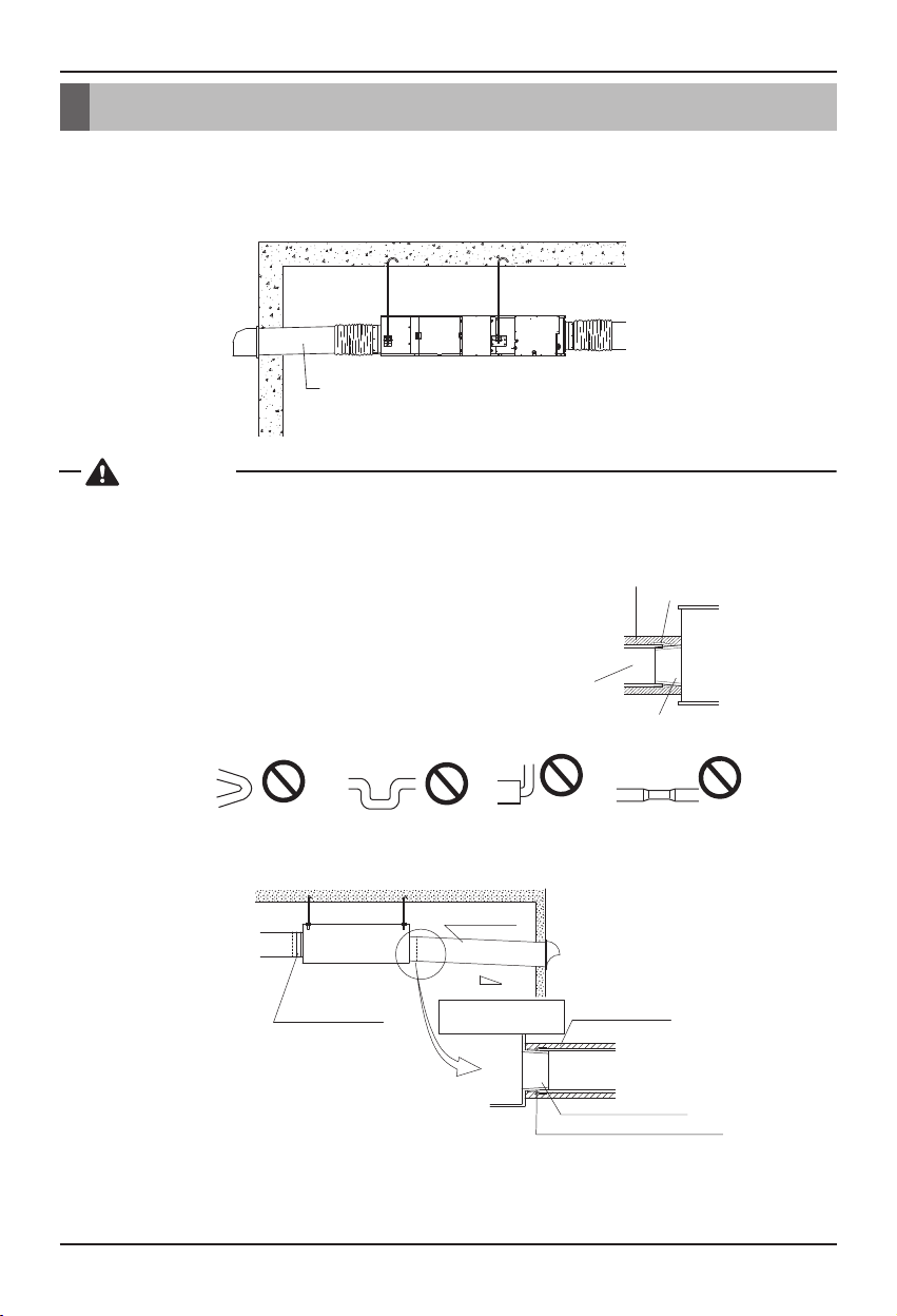
• Keep the drain pipe short and sloping downwards at a gradient of at least 1/100 to prevent air pock-
ets from forming.
• If converging multiple drain pipes, install according to the procedure shown below. (Install a drain
trap for each indoor unit.)
CAUTION
Drain Piping and Water Supply Work
• Always lay the drain with downward
inclination (1/100 to 1/50).
Prevent any upward flow or reverse flow
in any part.
• 10mm or thicker formed thermal insulator
shall always be provided for the drain
pipe.
CORRECT
• Install the P-Trap (or U-Trap) to prevent
a water leakage caused by the blocking
of intake air filter.
Unit
Make sure to be closed.
• Upward routing not
allowed
INCORRECT
Applied U-Trap Dimension
≥
70 mm
A
B ≥ 2C
C
≥
2 x SP
SP = External Pressure
(mmAq)
Ex) External Pressure
= 10 mmAq
A ≥ 70 mm
B ≥ 40 mm
C ≥ 20 mm
Thermal insulator
(Local supply)
Drainage pipe
(Local supply)
Drainage hole
C
A
B
U-Trap
Page 16

Drain Piping and Water Supply Work
16 Ventilator
•
Test the drainage by pouring 1000cc of water into the drain pan through the inspection hole by removing the maintenance cover (8 screws) or through the outlet duct joint of supply air to room (SA).
• Make sure that heat insulation work is executed on the Indoor drain piping and Drain outlet to prevent any possibility water leakage due to dew condensation.
Check the drainage
• Connect the water supply with strainer, other pipes and valves (locally procured) to the indoor unit as
shown in the figure at below.
Install the water supply piping
When installing the water supply piping, wash the pipes with tap water so that all dirt is removed from
them or install a drain valve somewhere along the piping and drain the pipes thoroughly until the water
flowing through them is clear. Make sure no cutting oils or detergents get into the pipes.
CAUTION
Maintenance cover
Drain piping
(Locally procured)
Drain outlet
Duct connecting flange (SA)
Flexible hose
Feed Water
Water supply piping
with strainer
Water supply shut-off
valve
Water supply pipe
(Locally procured)
(Locally procured)
(Locally procured)
(Locally procured)
(Locally procured)
Cap
Drain valve
Drain outlet
Duct connecting flange (SA)
Page 17

Drain Piping and Water Supply Work
Installation Manual 17
ENGLISH
• After checking that the drain piping connections do no leakage, insulate them using the insulation.
(Tighten with a clamp material)
• Wrap the drain piping with insulation to prevent condensation from forming.
Insulate all piping that passes indoors
When installing the water supply piping, wash the pipes with tap water so that all dirt is removed from
them or install a drain valve somewhere along the piping and drain the pipes thoroughly until the water
flowing through them is clear. Make sure no cutting oils or detergents get into the pipes.
CAUTION
Tie wrap
(Locally procured)
Insulation
(for drain piping)
Page 18
18 Ventilator
Duct Connection
Duct Connection
• The change of air discharge grill’s location should be examined when the cold draft from air discharge grill is feared. The fan is driving while defrost operation, and the cold air is often blowing.
• After securely connect the duct with the duct connection flange, wrap it with a commercial aluminium
tape so that air cannot be leaked.
• Adjust the duct from the ceiling so that no force is applied to the main body of the ventilation system.
• Always use two ducts at the outdoor with the heat insulating material for prevention of dewing.
Aluminum tape
(Locally procured)
Aluminum tape (Locally procured)
Insulation material
(Locally procured)
Slope :
Over 1/30
Outdoor duct
Make sure there
is no slack in the duct.
Duct connecting flange
Duct to OA
Main Body
Heat Insulating Material
Aluminium
Duct Connection Flange
Rapid Bending Excessive Bending
Too Close Bending
to Outlet
Rapid Reduction of
Duct Diameter
• Check that there are no foreign materials
(paper, vinyl, etc) or cutoff powders in the
duct before connecting the duct.
•
Take care so that shock may not be applied
to the damper plate within the main body
when performing the duct connection work.
•
It is recommended to perform adiabatic treatment even to the duct pipe at the indoor side
where ambient temperature is expected when
the main body of the ventilation system for cooling in summer.
•
Take care so that work may not be performed
as in the left figure. Otherwise, it may cause
reduction of air volume or abnormal noise.
CAUTION
Outdoor duct slop
: More than 1/30(toward the wall)
Obtaining of right distance
(preventing penetration of rain water)
Page 19

Installation Manual 19
ENGLISH
Connecting Pipes
Main cause of gas leakage is defect in flaring
work. Carry out correct flaring work in the following procedure.
Cut the pipes and the cable.
• Use the accessory piping kit or the pipes purchased locally.
• Measure the distance between the indoor and
the outdoor unit.
• Cut the pipes a little longer than measured distance.
•
Cut the cable 1.5m longer than the pipe length.
Burrs removal
• Completely remove all burrs from the cut cross
section of pipe/tube.
•
Put the end of the copper tube/pipe to downward
direction as you remove burrs in order to avoid to
let burrs drop in the tubing.
Putting nut on
• Remove flare nuts attached to indoor and outdoor units, than put them on pipe/tube having
completed burr removal.
(Not possible to put them on after flaring work)
Flaring work
•
Carry out flaring work using dedicated flaring tool
for R-410A as shown below.
Firmly hold copper tube in a bar(or die) as indicated dimension in the table above.
Check
• Compare the flared work with figure below.
• If flare is noted to be defective, cut off the flared
section and do flaring work again.
Outside diameter "A"
mm inch mm
Ø6.35 1/4 1.1~1.3
Ø9.52 3/8 1.5~1.7
Ø12.7 1/2 1.6~1.8
Ø15.88 5/8 1.6~1.8
Ø19.05 3/4 1.9~2.1
Connecting Pipes
Preparation of Piping
Copper
tube
Point down
Copper tube
Slanted Uneven Rough
90°
Pipe
Flare nut
Reamer
Bar
Copper pipe
Smooth all round
Even length
all round
Handle
Bar
"A"
Clamp handle
Inside is shining without scratches
= Improper flaring =
Inclined
Surface
damaged
Yoke
Red arrow mark
Cracked Uneven
thickness
Cone
Page 20

20 Ventilator
Connecting Pipes
Connecting the pipings to the indoor unit and drain hose to drain pipe
Insulation, Others
• Align the center of the pipings and sufficiently
tighten the flare nut by hand.
• Tighten the flare nut with a wrench.
• When extending the drain hose at the indoor
unit, install the drain pipe.
• Insulate the joint and tubes completely
mm inch kg.m
Ø6.35 1/4 1.8~2.5
Ø9.52 3/8 3.4~4.2
Ø12.7 1/2 5.5~6.6
Ø15.88 5/8 6.6~8.2
Ø19.05 3/4 9.9~12.1
Outside diameter Torque
All thermal insulation must comply with local requirement.
THERMAL INSULATION
Indoor unit tubing Flare nut Pipings
Spanner (fixed)
Flare nut
Torque wrench
Indoor unit tubing
Drain pipe
Adhesive
Indoor unit drain hose
Vinyl tape(narrow)
Connection pipe
Union for liquid pipe
Refrigerant pipe and thermal
insulator(Local supply)
Hose crip for thermal insulator
(Local supply)
Thermal insulator for refrigerant pipe
(Local supply)
Union for gas pipe
Thermal insulator for refrigerant pipe
(Local supply)
Hose crip for thermal insulator(Local supply)
Make sure that there is no clearance here.
Thermal insulator for
piping(Local supply)
Overlap with thermal
insulator for piping.
Page 21

Installation Manual 21
ENGLISH
Wire Specification
Power Cable Specification : The power cord
connected to the outdoor unit should be complied with IEC 60245 or HD 22.4 S4(Rubber
insulated cord, type 60245 IEC 66 or H07RN-F)
Precautions when laying power
wiring
Use round pressure terminals for connections
to the power terminal block.
• All wiring must comply with local requirements.
• Select a power source that is capable of supplying the current required by the ventilator.
• Use a recognized ELCB(Electric Leakage Circuit
Breaker) between the power source and the unit.
A disconnection device to adequately disconnect
all supply lines must be fitted.
• Model of circuit breaker recommended by authorized personnel only
When none are available, follow the instructions below.
• Do not connect wiring of different thicknesses to the power terminal block. (Slack in the power wiring
may cause abnormal heat.)
• When connecting wiring which is the same thickness, do as shown in the figure below.
Wiring Connection
Perform the electrical wiring work according to the electrical wiring connection.
Wiring Connection
Electrical Wiring
MCA : Min. Circuit Amps (A) ; MOP : Maximum Over current Protection
kW : Fan Motor Rated Output (kW) ; FLA : Full Load Amps (A)
Ventilation unit Power supply Fan motor
Hz Volts Voltage range MCA
2.8
2.8
2.8
8
8
8
0.2x2
0.2x2
0.2x2
1.25x2
1.25x2
1.25x2
MOP kW FLA
Max. 264V
Min. 198V
Model
LZ-H050GXN4 / LZ-H050GXH4
LZ-H080GXN4 / LZ-H080GXH4
LZ-H100GXN4 / LZ-H100GXH4
50
220-240 V
20mm
GN/YL
1 Phase(Ø)
Round pressure terminal
Power wire
Outdoor
Ventilation unit
Main
power source
Switch box
ELCB
Page 22

22 Ventilator
Wiring Connection
Make sure that the screws of the terminal are free from looseness.
WARNING
Connecting Cable Specification : The connecting cable, being used to connect the indoor
unit and outdoor unit, should be complied with IEC 60335-1 standard (This equipment shall
be provided with a cord set complying with the national regulation).
20mm
GN/YL
If the supply cable is damaged, it must be replaced by a special cable
or assembly available from the manufacturer or its service agent.
Page 23

Wiring Connection
Installation Manual 23
ENGLISH
Method to Connect Wiring
Make sure that the screws of the terminal are free from looseness.
WARNING
• Pass the power supply wiring and the ground wiring through the wiring through-hole into the electrical parts box and secure with the included clamping material after connecting the wires to terminal
blocks.
Connect the wires to the terminals on the control board individually according to the outdoor unitconnection.
• Ensure that the color of the wires of outdoor unit and the terminal No. are the same as those of
indoor unit respectively.
The Power cord connected to the unit should be selected according to the following
specifications .
CAUTION
Communication
Terminal Block
Input from outside
(Indoor unit or
MultiV outdoor unit)
Main Power
Terminal Block
Power supply wiring
Ground wiring
Accessory
Terminal Block
Short-circuit wire
Remove when installing
the humidistat.
(locally procured)
Terminal Block Indoor
34
1(L)2(N)
Ventilation unit
Power Input
SODU
BA BABA
INTERNET DRY1 DRY2 GND 12V
IDU
Outdoor unit
Page 24

24 Ventilator
Wiring Connection
Main PCB
Terminal Block
Power Supply
Wiring
Remote Controller
Wiring
485 PCB
Motor Driver PCB
Sub PCB
Screw
Clamp
• See “Label Circuit” on the backside of the cover of control box for electric wiring work.
• Be sure to attach the sealing material or putty (locally procured) to hole of wiring to prevent the
infiltration of water as well as any insects and other small creatures from outside. Otherwise a
short-circuit may occur inside the control box.
• When clamping the wires, be sure no pressure is applied to the wire connections by using the
included clamping material to make appropriate clamps. Also, when wiring, make sure the lid on
the control box fits snugly by arranging the wires neatly and attaching the control box cover firmly. When attaching the cover of control box, make sure no wires get caught in the edges. Pass
wiring through the wiring through holes to prevent damage to them.
• Make sure the remote controller wiring, the wiring between the units, and other electrical wiring
do not pass through the same locations outside of the unit, separating them by at least 50mm,
otherwise electrical noise (external static) could cause mistaken operation or breakage.
CAUTION
Clamping of cables
Arrange 2 power cables on the control panel.
First, fasten the Plastic clamp with screw to the inner boss of control panel.
Page 25

Installation Manual 25
ENGLISH
Wiring Connection
Wiring for the Humidity Regulator (Locally Procured)
<LZ-H***GXH series only>
Pass into the electric parts box together with the power wire through the power wiring through-hole.
Remove the short-circuit wires on the accessory terminal block and connect the wiring for the humidity
regulator.
Secure with cramping material together with the power wire.
Wiring specifications
Sheathed wire (should be complied with IEC60245 standard)
Size 0.75 - 1.25 mm
2
Length MAX. 100 m
External contact specifications Normally closed contact (Current tolerance 10 mA - 0.5 A)
• If using humidistat, install one per ventilation unit.
Controlling more than one ventilation unit with a single humidity controller may prevent normal
humidity operation and cause water leakage, etc.
CAUTION
Page 26

26 Ventilator
Wiring Example
• This unit can be used as part of the combined operation system used together with indoor units
(Multi-V system air conditioners), or as an independent system for processing outside air.
<Combined operation system with Multi-V system(connected with ventilation units and standard indoor units in a single refrigerant circuit)>
<Independent system (connected only with a ventilation unit in a single refrigerant circuit)>
GND
SIGNAL
Combined operated system
Communication line
LGAP Network System
12V
OK OK OK
Independent system
Communication line
LGAP Network System
OKOKOKOK
Wiring Connection
When this ventilation unit is combined with Multi V Plus 2 Series, sometimes the system does not
cooling operate for self protection in low ambient temperature when the capacity of IDU, which is connected to ventilation unit, is less than or equal to 10% of total capacity of all IDUs. In this case, the
capacity of the IDU connected to ventilation unit should be higher than 10% of total capacity of all
IDUs
CAUTION
Page 27

Installer Setting and Test Run
Installation Manual 27
ENGLISH
Installer Setting and Test Run
Installer setting -How to enter installer setting mode
Installer setting mode is to set the detail function of the remote controller.
If the installer setting mode is not set correctly, it can cause problems to the product, user injury or
property damage. This must be set by an certificated installer, and any installation or change that is
carried out by a non-certificated person should be responsible for the results. In this case, free service
cannot be provided.
CAUTION
•
Some categories of the menu may not be displayed according to the function of the product, or the menu name may be different.
• For more details, refer to the remote controller manual.
Accessory Model: PQRCVSL0/PQRCVSL0QW
If pressing button long for 3 seconds,
1
it enters into remote controller setter
setup mode.
- If pressing once shortly, it enters into
user setup mode. Please press more
than 3 seconds for sure.
When you enter the setting mode
2
initially, Function code is displayed on
the bottom of the LCD screen.
Function code Value
Page 28

Installer Setting and Test Run
28 Ventilator
Accessory Model: PREMTB100
• In the menu screen, press [<,>(left/right)] button to select the setting category, and press [∧(up)]
button for 3 seconds to enter the password input screen for the installer setting.
• Input the password and press [OK] button to move to the installer setting list.
※Installer setting password
Main screen → menu → setting → service → RMC version information → SW Version
Example) SW version : 1.00.1 a
In the above case, the password is 1001.
•
Some categories of the menu may not be displayed according to the function of the product, or the menu name may be different.
• For more details, refer to the remote controller manual.
Remote controller (PQRCVSL0/PQRCVSL0QW/ PREMTB100)
CO2sensor (AHCS100H0)
Available accessories
OK OK
Page 29

Installer Setting and Test Run
Installation Manual 29
ENGLISH
Installer Setting – Function explanation
Test Run
When installing the product, test operation for checking the installation status
Setting Address of Central Control
When connecting central control, it sets the address of central control address of indoor unit.
Supply/Exhaust ESP setting
Set the E.S.P(RPM) value of air conditioner indoor unit.
Production Direction
Set the installation direction of ventilation indoor unit.
Override Setting
Set the Override condition by setting the Mode Master/Slave of indoor unit.
<Override connecting Scene>
Mode Master Mode Slave Mode Slave Mode Slave
Outdoor
unit
OK OK OK OK
Remote
Controller
Remote
Controller
Remote
Controller
Remote
Controller
Page 30

30 Ventilator
Installer Setting and Test Run
Zone Stats
Set the wind strength option of indoor unit as Variable or fixed.
Selecting Celsius or Fahrenheit
Control the temperature control unit by changing it Celsius ↔ Fahrenheit.
Humidification for Singlar Ventilation
Set the power supply to humidification When operating Singular ventilation of Direct Expansion or
General Ventilation unit.
- When Humidification for ventilation is set
In case of connection with General Ventilation : When operation is On, you can control the humidification
In case of connection with Direct Expansion Ventilation: When ventilation is operated only, you
can control the humidification. (When operating DX Coil, impossible to control humidification)
Humidification for Heat Mode Ventilation
Set the Humidification for Heat mode of direct expansion ventilation as automatic setting or manual
setting.
- Automatic setting
If air conditioner operation mode is set as heat, it automatically switches on the humidification.
- Manual setting
If air conditioner operation mode is set as heat, you could turn on the humidification manually.
(When it is set as heat mode, even the humidification is on, you cannot turn it off manually.)
- Humidification cancellation
In case of the cancellation of heating operation, the product is off.
- Power failure compensation
When power failure compensation, receive the automatic/manual data from the indoor unit to set
the Value.
Page 31
Installation Manual 31
ENGLISH
Installer Setting and Test Run
Run the humidifier
<LZ-H***GXH series only>
Check that the water supply piping is connected securely.
Open the water supply shut-off valve. (No water will be supplied at this time.)
Run the ERV™ unit in heating mode. (See the operating manual included with the indoor unit for
details on how to run the unit in heating mode.) The water supply will start and the humidifier will begin
operation.
After starting heating (humidifying), the sound of the water supply solenoid valve will be heard at intervals of several minutes (a clicking sound), so listening for that clicking sound let the unit run for 30
minutes to make sure that humidifying operation is normal.
If carpentry work is not completed when a test run is finished, tell the customer not to run the humidifier for the protection of indoor unit and ERV™ until it is completed.
If the humidifier is run, paint, particles generated from adhesive and other materials used for carpentry
work may cause ERV™ to get dirty, causing splash or leakage of water.
CAUTION
Page 32

32 Ventilator
In case of finding a problem at a test run
The Product doesn't work
The Product doesn't work through
you press the 'ON' switch
Even though you change the
fan speed, the operation mode
doesn't change and it changes
to 'Auto or Low'
Even though you push the button of remote controller, any
function doesn't work.
Is power not supplied?
Is the Indoor temperature less
than 45°c or more than 40°C?
Is the Indoor temperature less
than -10°C or more than 45°C?
Is the icon " " displaying on
remote controller?
Is the icon " " displaying
on remote controller? Does the
message "HL" display on
remote controller when you
push the button.
Supply Power
It's standby mode for protecting
Total Heat Exchanger.
It's operation mode to protect
Total Heat Exchanger.
It's Child Lock mode. Refer to
Remote controller.
It's centralized control mode.
You can't control on remote
controller.
Symptom Check Item Counter-measure
In case of finding a problem at a test run
The A-weighted sound pressure emitted by this product is below 70 dB.
** The noise level can vary depending on the site.
The figures quoted are emission level and are not necessarily safe working levels. Whilst there is a
correlation between the emission and exposure levels, this cannot be used reliably to determine
whether or not further precautions are required. Factor that influence the actual level of exposure of the
workforce include the characteristics of the work room and the other sources of noise, i.e. the number
of equipment and other adjacent processes and the length of time for which an operator exposed to
the noise. Also, the permissible exposure level can vary from country to country. This information, however, will enable the user of the equipment to make a better evaluation of the hazard and risk.
Limiting concentration: 0.44kg/m3(R410A)
Airborne Noise Emission
Limiting concentration is the limit of Freon gas concentration where immediate measures can be
taken without hurting human body when refrigerant leaks in the air. The limiting concentration shall
be described in the unit of kg/m3(Freon gas weight per unit air volume) for facilitating calculation
n Calculate refrigerant concentration
Refrigerant concentration =
Limiting concentration
Total amount of replenished refrigerant in refrigerant facility (kg)
Capacity of smallest room where indoor unit is installed (m
3
)
Page 33

 Loading...