

LG LZ-H025GBA3 INSTALLATION MANUAL
www.lg.com
INSTALLATION MANUAL
AIR
CONDITIONER
P/NO : MFL67855522
Please read this installation manual completely before installing the product.
Installation work must be performed in accordance with the national wiring standards
by authorized personnel only.
Please retain this installation manual for future reference after reading it thoroughly.
[
Representative] LG Electronics Inc. EU Representative : LG Electronics European Shared
Service Center B.V. Krijgsman 1, 1186 DM Amstelveen, The Netherlands
[Manufacturer] LG Electronics Inc. Changwon 2nd factory 84, Wanam-ro, Seongsan-
gu, Changwon-si, Gyeongsangnam-do, KOREA
VENTILATOR
Original instruction
ITALIANO
ESPAÑOL
FRANÇAIS
DEUTSCH
ΕΛΛΗΝΙΚΆ
ČEŠTINA
NEDERLANDS
POLSKI
LIMBA ROMÂNĂ
ENGLISH

2 Ventilator
Ventilator Installation Manual
TABLE OF CONTENTS
Safety Precautions...............3
Introduction ..........................8
Symbols used in this
Manual.................................8
Feature Dimension
Diagram...............................8
Installation ..........................10
Installation Map .................10
Installation of Main Body....11
Connection of Duct ............11
Method to Connect
Power Cord .......................12
How to connect Remote
Controller(Accessory) .......14
Name and Function of
Remote Controller .............14
Installation instruction........15
Group control.....................17
Installer Setting -How to enter
installer setting mode ........19
How to connect Central Con-
troller(Accessory) ..............21
Trial Operation....................22
Method to Operate and
Select Air Volume –Ventila-
tion Single Operation.........22
Method to Operate and
Select Air Volume – Interlinked Operation with Ventila-
tion.....................................23
In case of finding a problem
at a trial operation..............24
Model Designation.............25
Airborne Noise Emission ...25
• Washer
• Nuts
• Ceiling Fixing Bolt(M 10)
• Aluminum Tape
• Screws
• Screw Driver
• Spanner
• Cutter
• Cutter
• Screw Driver
Installation
Requirements
Required Parts Required Tools
Safety Precautions
Installation Manual 3
Safety Precautions
To prevent injury to the user or other people and property damage, the following instructions
must be followed.
n Incorrect operation due to ignoring instruction will cause harm or damage. The seriousness is
classified by the following indications.
n Meanings of symbols used in this manual are as shown below.
WARNING
CAUTION
This symbol indicates the possibility of death or serious injury.
This symbol indicates the possibility of injury or damage.
Be sure not to do.
Be sure to follow the instruction.
ENGLISH
n Installation
Do not use a defective or underrated circuit breaker. Use this
appliance on a dedicated circuit.
• There is risk of fire or
electric shock.
For electrical work,
contact the dealer,
seller, a qualified
electrician, or an
Authorized Service
Center.
• Do not disassemble or
repair the product.
There is risk of fire or
electric shock.
Always ground the
product.
• There is risk of fire or
electric shock.
Install the panel and
the cover of control
box securely.
• There is risk of fire or
electric shock.
Always install a dedicated circuit and
breaker.
• Improper wiring or
installation may cause
fire or electric shock
Use the correctly rated
breaker or fuse.
• There is risk of fire or
electric shock.
WARNING

Safety Precautions
4 Ventilator
For installation,
always contact the
dealer or an Authorized Service Center.
• There is risk of fire,
electric shock, explosion, or injury.
Do not install the
product on a defective installation
stand.
• It may cause injury,
accident, or damage to
the product.
Do not let the product
run for a long time when
the humidity is very
high and a door or a
window is left open.
• Moisture may condense
and wet or damage furniture.
Do not modify or
extend the power
cable.
• There is risk of fire or
electric shock.
Do not install, remove,
or re-install the unit by
yourself (customer).
• There is risk of fire,
electric shock, explosion, or injury.
Be cautious when
unpacking and
installing the product.
• Sharp edges could
cause injury.
Install the air intake
where polluted air
can not be directly
sucked in.
•
It may cause various accidents, including suffocation, due to the suction of
harmful gasses(CO, etc.)
Do not install this
product in a refrigerated warehouse,
heated swimming
pool or other location
where the temperature and humidity are
significantly different.
• There is risk of electrical
shock, malfunctioning.
Install this product in an
environment where the
temperature ranges
from –10°C to +45°C and
the relative humidity is
less than 80%. It condensation is expected to
form, heat up the fresh
outside air using a duct
heater etc.
For re-installation of
the installed product,
always contact the
dealer or an Authorized Service Center.
• There is risk of fire,
electric shock, explosion
or injury.
Do not open the
maintenance cover of
the main body during
operation.
• Otherwise, it may cause
electrical shock.
Use the outdoor air
suction hole with the
net installed to
ensure that birds
could not come in.
•
Remove estrange things
like the bird’s nest. Otherwise, it may cause scarcity of indoor oxygen.

Safety Precautions
Installation Manual 5
ENGLISH
Install this product in
and environments
where the outside air
intake meets the following conditions:
temperature range is
between –15°C and
+40°C and the relative humidity is 80%
or less.
Use the designated
electrical wires for
the terminal board
connections, and
connect the wires
securely so that they
will not become disconnected. (Failure
to ensure proper connections may cause
fire.)
When passing metal
ducts through wooden
buildings clad with
metal laths, wire laths
or metal, these ducts
must be installed in
such a way that they
will not make electrical
contact with the metal
laths, wire laths or
metal sheets. (Power
leakage can cause
ignition)
When the product is
soaked (flooded or
submerged), contact
an Authorized Service
Center.
• There is risk of fire or
eletric shock.
Don't touch a dedicated circuit or breaker
with wet hands.
• There is risk of electric
shock.
Do not store or use
flammable gas or
combustibles near
the product.
• There is risk of fire or
failure of product.
n Operation
When flammable gas
leaks, turn off the gas
and open a window for
ventilation before turn
the product on.
•
Do not use the telephone or turn switches
on or off. There is risk
of explosion or fire
Be cautious that
water could not enter
the product.
• There is risk of fire,
electric shock, or product damage.
Turn the breaker off
when cleaning or
maintaining the product.
• There is risk of electric
shock.
Safety Precautions
6 Ventilator
CAUTION
Keep level even when
installing the product.
• To avoid vibration or
water leakage.
Use two or more people to lift and transport the product.
• Avoid personal injury.
Do not install the
product where it will
be exposed to sea
wind (salt spray)
directly.
• It may cause corrosion
on the product. Corrosion, particularly on the
condenser and evaporator fins, could cause
product malfunction or
inefficient operation.
Don't connect the
ground wire to the window frame or water
cock.
• There is risk of electric
shock.
Do not install the product at a smoky and oily
place like kitchen or
factory.
• Otherwise. oil may
adhere to the filter or
heating exchanger and
cause trouble.
Install the product in
an insulated space
from outdoor air.
• In case of installing the
product outside of the
insulated layer, dewing
occurs inside of the
main body in winter.And
it causes electrical
shock or falling of condensed water.
n Installation
The outside ducts must be tilted
at a gradient (1/30 or more) down
toward the outdoor area from the
ventilator unit, and properly insulated. (The entry of rain water may
cause power leaks, fire or damage
to household property.)
Glove should be worn when doing
the installation work. (There is
risk of injury.)

Safety Precautions
Installation Manual 7
ENGLISH
Use a soft cloth to
clean. Do not use
harsh detergents, wax
or thinner, etc.
• Otherwise, color or surface of the oroduct mav
deteriorate.
Clean the filter and the
heat exchanger regularly and use the
gloves for cleaning.
• Adhering to a mass of
dust may cause the
deterioration of air volume.
Do not use the product
for special purposes,
such as preserving
foods, works of art,
etc. It is a consumer
ventilator, not a precision refrigeration system.
• There is risk of damage or loss of property.
n Operation
Do not block the inlet or outlet of
air flow.
• It may cause product failure.
Do not step on or put anyting on
the product.
• There is risk of personal injury and
failure of product.
Introduction
8 Ventilator
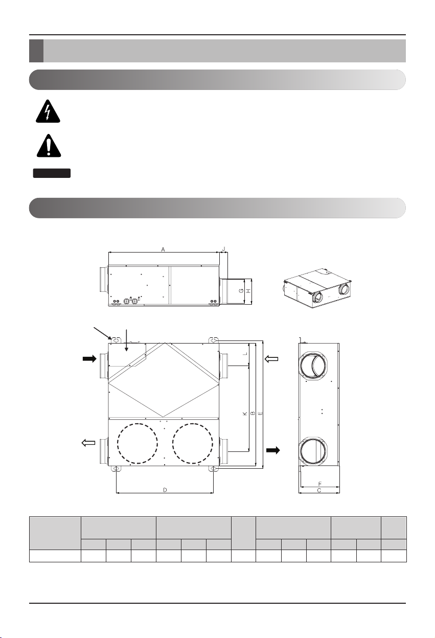
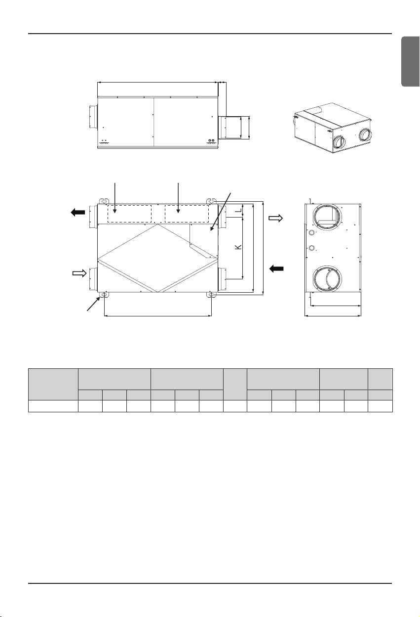
Model
680 750 250 596 781 237 150 146 156 51 522 139 30
A B C D E F G H J K L kg
LZ-H025GBA3
Figure Duct Pitch Weight
Pitch of Suspension Fix-
ture
Duct Connection Flange
Nominal
Diameter
Model : LZ-H025GBA3
Unit : mm
h
It necessary to secure sufficient space for maintenance more than the dimensions described in the
product service.
This symbol alerts you to the risk of electric shock.
This symbol alerts you to hazards that could cause harm to the
product.
This symbol indicates special notes.
Feature Dimension Diagram
Symbols used in this Manual
Introduction
NOTICE
Suspension Fixture
RA
(Return Air)
SA
(Supply Air)
Control Box
Blower for
Supply Air
Total Heat Exchanger
Blower for
Exhaust Air
OA
(Outdoor Air)
EA
(Exhaust Air)
Introduction
Installation Manual 9
Model : LZ-H035GBA3
h
It necessary to secure sufficient space for maintenance more than the dimensions described in the
product service.
ENGLISH
Model
750 600 350 668 632 314 150 146 155 50 422 89 33
A B C D E F G H J K L kg
LZ-H035GBA3
Figure Duct Pitch Weight
Pitch of Suspension Fix-
ture
Duct Connection Flange
Nominal
Diameter
Unit : mm
Blower for Exhaust Air
EA
(Exhaust Air)
OA
(Outdoor Air)
Suspension Fixture
A
Blower for Supply Air
D
J
Control Box
H
G
SA
(Supply Air)
B
E
RA
(Return Air)
F
C
 Loading...