


P/NO : MFL67855502
www.lg.com
INSTALLATION MANUAL
AIR CONDITIONER
• Please read this installation manual completely before installing the product.
• Installation work must be performed in accordance with the national wiring
standards by authorized personnel only.
• Please retain this installation manual for future reference after reading it
thoroughly.
TYPE : VENTILATOR
Original instruction
ITALIANO ESPAÑOL
FRANÇAIS
DEUTSCH
ΕΛΛΗΝΙΚΆ
ČEŠTINA
NEDERLANDS
POLSKI
LIMBA ROMÂNĂ
ENGLISH
PORTUGUESE
MAGYAR
БЪЛГАРСKN
SRPSKI
HRVATSKI SVENDKA
NORSK SUOMI DANSK

2 Ventilator
Ventilator Installation Manual
TABLE OF CONTENTS
Safety Precaution.................3
Introduction ..........................6
Symbols Used in
this manual ..........................6
Feature Dimension
Diagram...............................6
Installation ..........................11
Installation Map..................11
Installation of Main Body ...14
Connection of Duct............14
Method to Connect
Power Cord .......................16
How to Connect Remote
Controller(Accessory) .......17
Name and Function of
Remote Controller .............17
Installation instruction........18
Group control.....................20
Installer Setting -How to enter
installer setting mode ........22
How to connect Central
Controller(Accessory) .......24
Trial Operation....................25
Method to Operate and Select
Air Volume –Ventilation Single
Operation
...........................25
Method to Operate and Select
Air Volume – Interlinked
Operation with Ventilation.
..26
In case of finding a problem
at a trial operation..............27
Model Designation
..............28
Airborne Noise Emission ...28
• Screws
• Nuts
• Ceiling Fixing Bolt(M10~12)
• Washer
• Aluminium Tape
• Screws
• Screw Driver
• Spanner
• Cutter
• Cutter
• Screw Driver
Installation
Requirements
Required Parts Required Tools
Safety Precautions
Installation Manual 3
Safety Precautions
To prevent injury to the user or other people and property damage, the following instructions
must be followed.
n Incorrect operation due to ignoring instruction will cause harm or damage. The seriousness is
classified by the following indications.
n Meanings of symbols used in this manual are as shown below.
This symbol indicates the possibility of death or serious injury.
This symbol indicates the possibility of injury or damage.
Be sure not to do.
Be sure to follow the instruction.
n Installation
Do not use a defective or underrated circuit breaker. Use
this appliance on a dedicated circuit.
• There is risk of fire or electric
shock.
For electrical work, contact
the dealer, seller, a qualified
electrician, or an Authorized
Service Center.
• Do not disassemble or repair the
product. There is risk of fire or
electric shock.
Always ground the product.
• There is risk of fire or electric
shock.
Install the panel and the
cover of control box securely.
• There is risk of fire or electric
shock.
Always install a dedicated
circuit and breaker.
• Improper wiring or installation
may cause fire or electric shock
Use the correctly rated
breaker or fuse.
• There is risk of fire or electric
shock.
Do not modify or extend the
power cable.
• There is risk of fire or electric
shock.
Do not install, remove, or reinstall the unit by yourself
(customer).
• There is risk of fire, electric
shock, explosion, or injury.
Be cautious when unpacking
and installing the product.
• Sharp edges could cause injury.
ENGLISH

Safety Precautions
4 Ventilator
For installation, always contact the dealer or an Authorized Service Center.
• There is risk of fire, electric
shock, explosion, or injury.
Do not install the product on a
defective installation stand.
• It may cause injury, accident, or
damage to the product.
Do not let the product run for a
long time when the humidity is
very high and a door or a window is left open.
• Moisture may condense and wet
or damage furniture.
For re-installation of the installed product, always contact the dealer or an
Authorized Service Center.
• There is risk of fire, electric shock,
explosion or injury.
Do not open the maintenance cover of the main
body during operation.
• Otherwise, it may cause electrical
shock.
Use the outdoor air suction
hole with the net installed to
ensure that birds could not
come in.
• Remove estrange things like the
bird’s nest. Otherwise, it may
cause scarcity of indoor oxygen.
Install the air intake where
polluted air can not be directly sucked in.
•
It may cause various accidents, including suffocation, due to the suction of harmful gasses(CO, etc.)
Do not install this product in
a refrigerated warehouse,
heated swimming pool or
other location where the
temperature and humidity
are significantly different.
• There is risk of electrical shock,
malfunctioning.
Install this product in an environment where the temperature
ranges from –10°C to +45°C and
the relative humidity is less than
80%. It condensation is expected
to form, heat up the fresh outside
air using a duct heater etc.
Install this product in and environments where the outside air
intake meets the following conditions: temperature range is
between –15°C and +40°C and
the relative humidity is 80% or
less.
Use the designated electrical
wires for the terminal board
connections, and connect the
wires securely so that they will
not become disconnected. (Failure to ensure proper connections may cause fire.)
When passing metal ducts
through wooden buildings clad
with metal laths, wire laths or
metal, these ducts must be installed in such a way that they
will not make electrical contact
with the metal laths, wire laths
or metal sheets. (Power leakage
can cause ignition)
Avoid fire equipment
• There is risk of fire.
When the product is soaked
(flooded or submerged), contact
an Authorized Service Center.
• There is risk of fire or eletric shock.
Don't touch a dedicated circuit
or breaker with wet hands.
• There is risk of electric shock.
n Operation
When the product is not be
used for a long time, disconnect the power supply plug or
turn off the breaker.
• There is risk of product damage or
failure, or unintended operation.
Do not store or use flammable
gas or combustibles near the
product.
• There is risk of fire or failure of
product.
When flammable gas leaks,
turn off the gas and open a
window for ventilation before turn the product on.
• Do not use the telephone or
turn switches on or off.
There is risk of explosion or fire
Safety Precautions
Installation Manual 5
Be cautious that water could not enter the
product.
• There is risk of fire, electric shock, or product damage.
Turn the breaker off when cleaning or maintaining the product.
• There is risk of electric shock.
The outside ducts must be tilted at a gradient
(1/30 or more) down toward the outdoor area
from the ventilator unit, and properly insulated.
(The entry of rain water may cause power
leaks, fire or damage to household property.)
Glove should be worn when doing the installation work. (There is risk of injury.)
Don't connect the ground wire
to the window frame or water
cock.
• There is risk of electric shock.
Do not install the product at a
smoky and oily place like
kitchen or factory.
• Otherwise. oil may adhere to the filter or heating exchanger and cause
trouble.
Install the product in an insulated space from outdoor air.
• In case of installing the product outside of the insulated layer, dewing
occurs inside of the main body in
winter.And it causes electrical shock
or falling of condensed water.
n Installation
Keep level even when installing the product.
• To avoid vibration or water leakage.
Use two or more people to
lift and transport the product.
• Avoid personal injury.
Do not install the product where
it will be exposed to sea wind
(salt spray) directly.
• It may cause corrosion on the
product. Corrosion, particularly on
the condenser and evaporator fins,
could cause product malfunction or
inefficient operation.
Use a soft cloth to clean. Do
not use harsh detergents, wax
or thinner, etc.
• Otherwise, color or surface of the
oroduct mav deteriorate.
Clean the filter and the heat
exchanger regularly and use
the gloves for cleaning.
• Adhering to a mass of dust may
cause the deterioration of air volume.
Do not use the product for special
purposes, such as preserving
foods, works of art, etc. It is a
consumer ventilator, not a precision refrigeration system.
• There is risk of damage or loss of
property.
n Operation
Do not block the inlet or outlet of air flow.
• It may cause product failure.
Do not step on or put anyting on the product.
• There is risk of personal injury and failure of product.
ENGLISH
Introduction
6 Ventilator
A J
G
H
K L
B
E
C
F
D
Suspension Fixture
Blower for Supply Air
Blower for Exhaust
(Exhaust Air) (Supply Air)
(Return Air)
(Outdoor Air)
Air
SA
RA
EA
OA
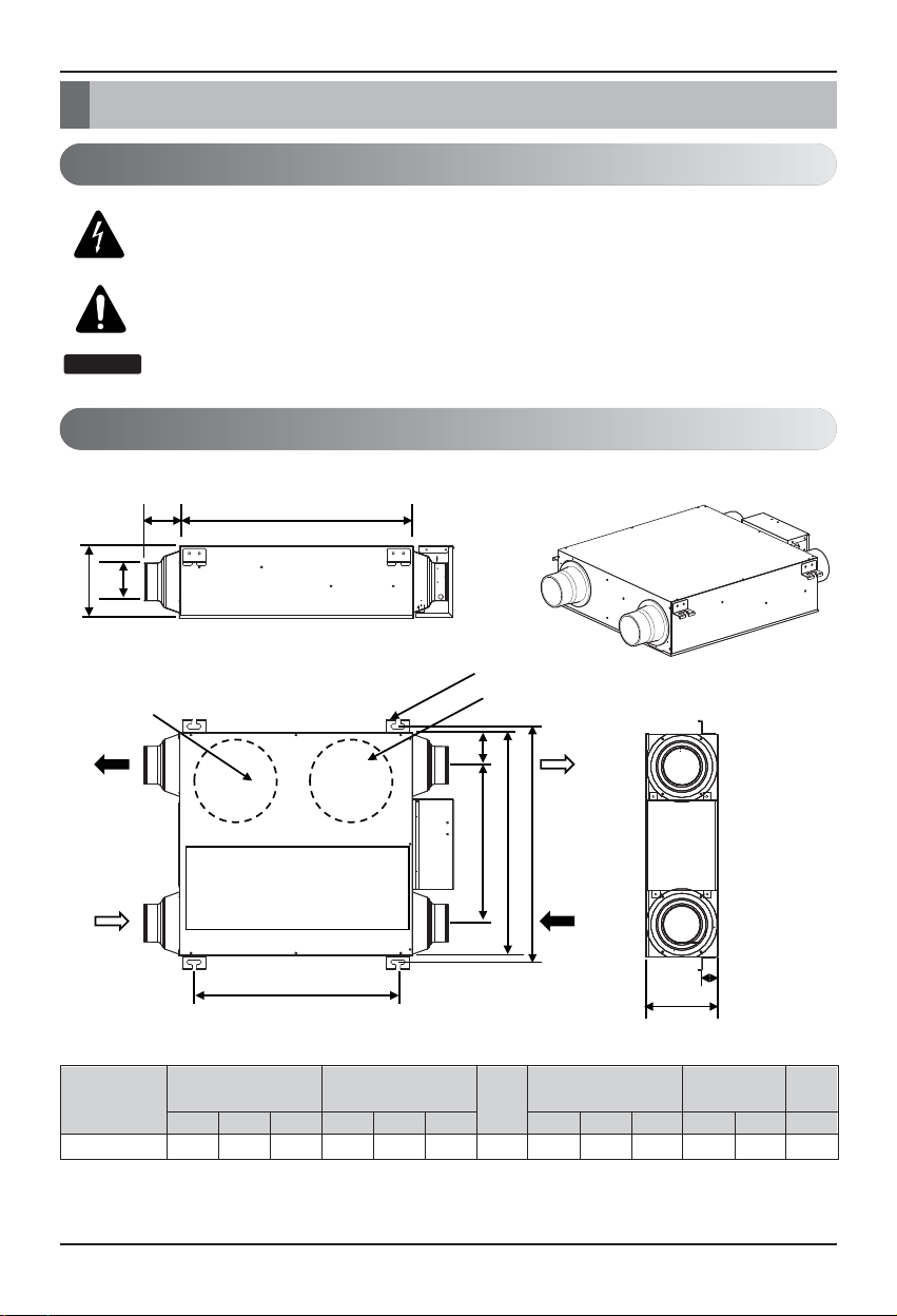
Introduction
Symbols used in this Manual
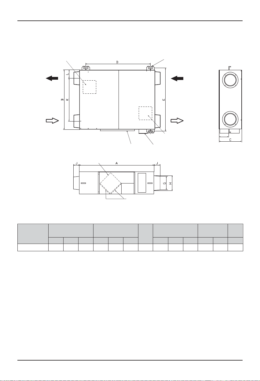
Feature Dimension Diagram
This symbol alerts you to the risk of electric shock.
This symbol alerts you to hazards that could cause harm to the
product.
This symbol indicates special notes.
Model
605 570 185 525 603 40 100 97 184 90 394 100 22
A B C D E F G H J K L kg
LZ-H015GBA2
Figure Duct Pitch Weight
Pitch of Suspension Fix-
ture
Duct Connection Flange
Nominal
Diameter
Model : LZ-H015GBA2
Unit : mm
h
It necessary to secure sufficient space for maintenance more than the dimensions described in the
product service.
NOTICE
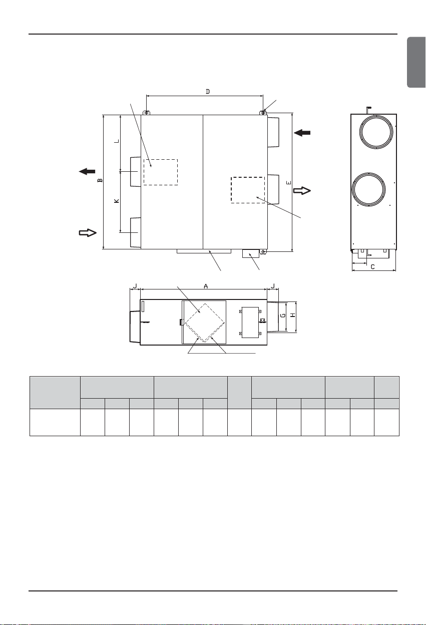
Introduction
Installation Manual 7
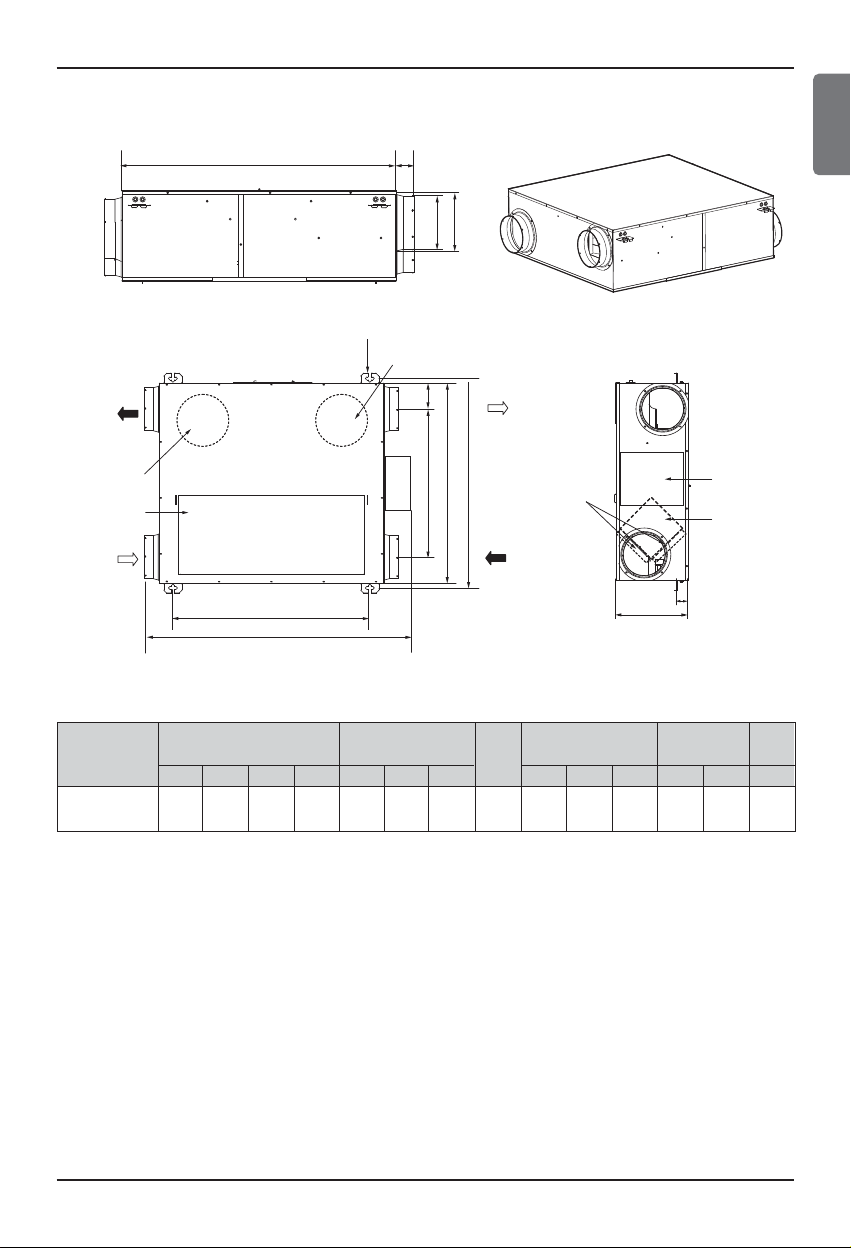
Model : LZ-H025GBA2 / LZ-H035GBA2
Model
750 680 250 850 657 711 40 150 146 155 50 502 89.2 32
A B C D E F G H J K L M kg
LZ-H025GBA2
LZ-H035GBA2
Figure Duct Pitch Weight
Pitch of Suspension Fix-
ture
Duct Connection Flange
Nominal
Diameter
Unit : mm
h
It necessary to secure sufficient space for maintenance more than the dimensions described in the
product service.
ENGLISH
A K
Suspension Fixture
Blower for Supply Air
J
H
EA
(Exhaust Air)
Blower for Exhaust Air
Maintenance Cover
OA
(Outdoor Air)
M
L
B
E
D
F
SA
(Supply Air)
RA
(Return Air)
Air Filter
Control Box
Total Heat
Exchanger
G
C
Introduction
8 Ventilator
Model : LZ-H050GBA2
Model
1014 988 273 939 1025 135 200 194 252 96 590 198 44
A B C D E F G H J K L kg
LZ-H050GBA2
Figure Duct Pitch Weight
Pitch of Suspension Fix-
ture
Duct Connection Flange
Nominal
Diameter
Unit : mm
h
It necessary to secure sufficient space for maintenance more than the dimensions described in the
product service.
EA
(Exhaust Air)
OA
(Outdoor Air)
Blower for Exhausting Air
Suspension Fixture
RA
(Return Air)
SA
(Supply Air )
Blower for Supplying Air
Air Filter
Control box
Maintenance Cover
Total Heat Exchanger
F
Introduction
Installation Manual 9
Blower for Exhausting Air
Blower for
Supplying Air
Control box
Suspension Fixture
Maintenance Cover
Total Heat Exchange Element
Air Filter
F
RA
(Return Air)
SA
(Supply Air)
OA
(Outdoor Air)
EA
(Exhaust Air)
Model : LZ-H080GBA2 / LZ-H100GBA2
Model
1062 1140 365 987 1176 180 250 242 253 98 513 481 60
A B C D E F G H J K L kg
LZ-H080GBA2
LZ-H100GBA2
Figure Duct Pitch Weight
Pitch of Suspension Fix-
ture
Duct Connection Flange
Nominal
Diameter
Unit : mm
h
It necessary to secure sufficient space for maintenance more than the dimensions described in the
product service.
ENGLISH

Introduction
10 Ventilator
Model : LZ-H150GBA2 / LZ-H200GBA2
h
It necessary to secure sufficient space for maintenance more than the dimensions described in the
product service.
D
O
RA
EA
B
N
E
SA
OA
Maintenance Cover
M
C
Model
LZ-H150GBA2
LZ-H200GBA2
AB
1313 1140 738 987 1176 339 242 253 98 340 350 140
L
K
Air Filter
Figure Weight
Pitch of Suspension
Fixture
CDEFG H J K L (kg)
Control Box
J
G
Total Heat Exchanger
Duct Connection Flange
H
Unit: mm
F

Installation Manual 11
Installation
Installation
Installation Map (LZ-H015GBA2/LZ-H025GBA2/LZ-H035GBA2)
n
A PLANE FIGURE
n
A FRONT VIEW
n
THREE DIMENSION VIEW
n
INSTALLATION OF MAINTENANCE COVER
ENGLISH
OA
EA
Duct slope: More than 1/30(wall side)
Obtaining of Right Distance
(Preventing Penetration of Rain Water)
New Type Hood
(Preventing Penetration of Rain Water)
EA
OA
Ventilator
Inspection Hatch
Duct
Ventilator
1m or more 1m or more
Inspection Hatch
RA Grille
Ceiling Fixing Bolt(Supplied by installer)
SA Grille
SA
RA
Control Box
RA GrilleSA Grille
SA Grille
605x575: LZ-H015GBA2
680x750: LZ-H025GBA2/LZ-H035GBA2:
OA
EA
Inspection Hatch
RA
SA

12 Ventilator
Installation
Installation Map (LZ-H050GBA2/LZ-H080GBA2/LZ-H100GBA2)
n
A PLANE FIGURE
n
A FRONT VIEW
n
THREE DIMENSION VIEW
n
INSTALLATION OF MAINTENANCE COVER
RA Grille
EA
OA
Duct slope: More than 1/30(wall side)
Obtaining of Right Distance
(Preventing Penetration of Rain Water)
New Type Hood
(Preventing Penetration of Rain Water)
EA
OA
Ventilator
Maintenance Space
Inspection Hatch
Duct
Ventilator
1m or more 1m or more
Inspection Hatch
Ceiling Fixing Bolt(Supplied by installer)
SA
SA Grille
RA
RA GrilleSA Grille
Maintenance Cover
Control Box
SA Grille
EA
Ventilator
Main Body
OA
More than 600
Maintenance Space
600x600
Inspection Hatch

Installation Manual 13
Installation
Installation Map (LZ-H150GBA2/LZ-H200GBA2)
xn
A PLANE FIGURE
xn
A FRONT VIEW
Maintenance Cover
Control Box
SA Grille
xn
THREE DIMENSION VIEW
xn
INSTALLATION OF MAINTENANCE COVER
ENGLISH
RA Grille
EA
OA
Duct slope: More than 1/30(wall side)
Obtaining of Right Distance
(Preventing Penetration of Rain Water)
New Type Hood
(Preventing Penetration
of Rain Water)
EA
OA
Ventilator
1m or more
Inspection
Hatch
Maintenance
Space
Inspection
Hatch
Ceiling Fixing Bolt(Supplied by installer)
RA RA
1m or more
RA Grille
SA Grille
SA SA
SA Grille
EA
OA
Ventilator
Main Body
More than 600
Maintenance Space
600x600
Inspection Hatch

14 Ventilator
Installation
Installation of Main Body
Assembly of Washer, Nut
Tighten the common washer and nut (more than 21mm
for the outside diameter of M10, to the commercial ceiling fixing bolt (M10) as shown in the right figure.
• For the ceiling fixing bolt, perform work less than
50mm under the ceiling fixing bracket.
Connection of Duct
1. After securely connect the duct with the duct connection flange, wrap it
with a commercial aluminium tape so that air cannot be leaked.
2. Adjust the duct from the ceiling so that no force is applied to the main
body of the ventilation system.
3. Always use two ducts at the outdoor with the heat insulating material for
prevention of dewing.
Duct
Taping
Ceiling Fixing Bolt
(M10)
Nut
Spring Washer
Washer
Nut

Installation Manual 15
Installation
Duct to OA
Main Body
Heat Insulating Material
Aluminium
Duct Connection Flange
Rapid Bending Excessive Bending
Too Close Bending
to Outlet
Rapid Reduction of
Duct Diameter
CAUTION:
• Check that there are no foreign materials (paper, vinyl, etc) or cutoff powders
in the duct before connecting the duct.
• Take care so that shock may not be
applied to the damper plate within the
main body when performing the duct
connection work.
• It is recommended to perform adia-
batic treatment even to the duct pipe
at the indoor side where ambient temperature is expected higher than room
temperature when the main body of
the ventilation system for cooling in
summer.
• Take care so that work may not be per-
formed as in the left figure. Otherwise,
it may cause reduction of air volume
or abnormal noise.
CAUTION:
•
In -10℃ below ambient temperature, when ventilation is installed the equivalent space in
the outdoor and outdoor, It may cause condensation, you must install drainage facilities(Drain Pan) and MD(Moterized Damper) at SA/RA duct.
ENGLISH

16 Ventilator
Installation
Cord Clamp
1(L) 2(N)
3(L) 4(N)
M.D.
PowerGND
GN/YL BR BL
Not
available
Method to Connect Power Cord
1. Release two screws and then open
the cover of the control box.
•
With reference to the below wiring diagram, accurately connect the main power cords into the
terminal block.
2. After inserting the power cord into the bushing,
fully insert it into the terminal block for connection.
• Fix the power cords with the clamp.
• Make sure that the power cords may not be removed by pulling them.
3. Wiring specifications
Wiring specifications
Sheathed wire (should be complied with IEC60245 standard)
Size 0.75 - 1.25mm
2
Length MAX. 100m
External contact specifications Normally closed contact (Current tolerance 10mA - 0.5A)
Precautions when laying power
wiring
Use round pressure terminals for connections to the power terminal block.
Round pressure terminal
Power wire
The Power cord connected to the unit should be selected according to the following specifications .
CAUTION
Cover of Control Box
Screw

Installation Manual 17
How to connect Remote Controller(Accessory)
Name and Function of Remote Controller
How to connect Remote Controller(Accessory)
OPERATION INDICATION
SCREEN
SET TEMPERATURE BUTTON
FAN SPEED BUTTON
ON/OFF BUTTON
OPRATION MODE SELECTION
BUTTON
WIRELESS REMOTE CON-
TROLLER RECEIVER
• Some products don't receive the
wireless signals.
AIR FLOW BUTTON
SUBFUNCTION BUTTON
FUNCTION SETTING BUTTON
VENTILATION BUTTON
RESERVATION
UP,DOWN,LEFT,RIGHT BUTTON
• To check the indoor temperature,
press button.
ROOM TEMPERATURE BUTTON
SETTING/CANCEL BUTTON
EXIT BUTTON
1
2
3
4
5
6
7
8
9
10
11
12
13
14
15
Connection Cable
(1EA, 10m)
Screw
(4 EA)
Owner's / Installation
manual
Inform label
(8EA-8Languages)
Accessory
j Some functions may not be operated and displayed depending on the product type.
Model : PQRCVSL0
PQRCVSL0QW
ENGLISH
1
10
9
8
7
11
12
13
14
15
Please attach the inform label inside of the door.
Please choose proper language depend on your
country.
2
3
4
5
6

18 Ventilator
How to connect Remote Controller(Accessory)
Installation instruction
2
2
1
3
3
<Wire guide grooves>
1. Please fix tightly using provided screw after placing remote controller setup board
on the place where you like to setup.
- Please set it up not to bend because poor setup could take place if setup board bends.
Please set up remote controller board fit to the reclamation box if there is a reclamation box.
2. Can set up Wired remote controller cable into three directions.
- Setup direction: the surface of wall reclamation, upper, right
- If setting up remote controller cable into upper and right side, please set up after removing remote controller
cable guide groove.
h
Remove guide groove with pliers.
①
Reclamation to the surface of the wall
②
Upper part guide groove
③
Right part guide groove

Installation Manual 19
How to connect Remote Controller(Accessory)
Wall
Side
Wall
Side
Wall
Side
Wall
Side
<Connecting order>
<Separating order>
3. Please fix remote controller upper part into
the setup board attached to the surface of
the wall, as the picture below, and then, connect with setup board by pressing lower part.
- Please connect not to make a gap at the remote controller
and setup board’s upper and lower, right and left part.
When separating remote controller from
setup board, as the picture below, after inserting into the lower separating hole using
screw driver and then, spinning clockwise,
remote controller is separated.
- There are two separating holes. Please individually sepa-
rate one at a time.
- Please be careful not to damage the inside
components when separating.
4. Please connect indoor unit and remote controller using connection cable.
5. Please use extension cable if the distance between wired remote controller and indoor unit is more than 10m.
Please check if connector is normally connected.
Connecting cable
Indoor
Unit side
When installing the wired remote controller, do not bury it in the wall.
(It can cause damage in the temperature sensor.)
Do not install the cable to be 50m or above.
(It can cause communication error.)
• When installing the extension cable, check the connecting direction of the connector of the remote controller
side and the product side for correct installation.
• If you install the extension cable in the opposite direction, the connector will not be connected.
• Specification of extension cable: 2547 1007 22# 2 core 3 shield 5 or above.
CAUTION
ENGLISH

20 Ventilator
GND
GND
12V
Signal wire
Signal wire
How to connect Remote Controller(Accessory)
GND
12V
B Y R B Y R
MASTER SLAVE
Signal wire
GND
12V
Signal wire
Group control
1. When installing more than 2
units of air conditioner to one
wired remote controller, please
connect as the right figure.
• If it is not event communication in-
door unit, set the unit as slave.
• Check for event communication
through the product manual.
2. When installing more than 2 wired remote controllers to one air conditioner,
please connect as the right picture.
• When installing more than 2 units of wired
remote controller to one air conditioner, set
one wired remote controller as master and
the others all as slaves, as shown in the
right picture.
• You cannot control the group as shown in
the right for some products.
•
Refer to the product manual for more detail.
When controlling multiple indoor units with event communication function with one remote controller, you must change the master/slave setting from the indoor unit.
- Indoor units, the master/slave configuration of the product after completion of indoor unit power
‘OFF’ and then ‘ON’ the power after 1 minutes elapsed sign up.
- For ceiling type cassette and duct product group, change the switch setting of the indoor PCB.
- For wall-mount type and stand type product, change the master/slave setting with the wireless
remote controller. (Refer to wireless remote controller manual for detail)
h When installing 2 remote controllers to one indoor unit with event communication function, set
the master/slave of the remote controller. (Refer to remote controller master/slave selection)
When controlling the group, some functions excluding basic operation setting, fan level
Min/Mid/Max, remote controller lock setting and time setting may be limited.
<When simultaneously connecting
2 sets of wired remote controller>
• When controlling in groups, set the master/slaver of the remote controller. Refer to Installer setting section on how to set master/slave for more detail.
#1 switch OFF: Master
(Factory default setting)
#1 switch ON: Slave
1ON2345678 1ON2345678

Installation Manual 21
How to connect Remote Controller(Accessory)
GND
SIGNAL
Combined operated system
Communication line
LGAP Network System
12V
PI485
Independent system
PI485
Communication line
LGAP Network System
•
This unit can be used as part of the combined operation system used together with indoor
units(Multi-V system air conditioners), or as an independent system for processing outside air.
<Combined operation system with Multi-V system(connected with ventilation units and
standard indoor units in a single refrigerant circuit)>
<Independent system (connected only with a ventilation unit in a single refrigerant circuit)>
ENGLISH

22 Ventilator
How to connect Remote Controller(Accessory)
Installer setting mode is to set the detail function of the remote controller.
If the installer setting mode is not set correctly, it can cause problems to the product, user injury or
property damage. This must be set by an certificated installer, and any installation or change that is carried out by a non-certificated person should be responsible for the results. In this case, free service
cannot be provided.
CAUTION
Installer Setting -How to enter installer setting mode
•
Some categories of the menu may not be displayed according to the function of the product, or the menu name may be different.
If pressing button long for 3 seconds,
1
it enters into remote controller setter
setup mode.
- If pressing once shortly, it enters into
user setup mode. Please press more
than 3 seconds for sure.
When you enter the setting mode
2
initially, Function code is displayed on
the bottom of the LCD screen.
Function Code Value

Installation Manual 23
How to connect Remote Controller(Accessory)
<Installer Setting Code Table>
1) General Ventilation product
No. Function Code Value
1 Test Run 01 01 : Test Run Setup
2 02 00~FF : Address of Central Control
3 SA(Supply Air) ESP 03 <ESP level> <ESP value> <Example>
4 EA(Exhaust Air) ESP 04
01 : Low 0~255
02 : High
03 : Super High
5 Product Direction 05
01 : Normal
02 : Opposite
6 Quick Refresh Priority 06
01 : Supply Air First
02 : Exhaust Air First
7 Master Setting 07
00 : Slave
01 : Master
8 Dry Contact 09
00 : Auto-Off
01 : Auto-On
9 Release Of 3 Minute Delay 10 01 : Set
10 Zone State 11
01 : Variable
02 : Fixed
Address Setting
j Some contents may not be displayed depending on the product function
ENGLISH
Function Code ESP valueESP step

24 Ventilator
How to connect Central Controller(Accessory)
1. Connect between PI485 Gate Way(CN-OUT) and Main PCB(CN-CC).
2. You do not need to set the Option Switch of Main PCB.
3. Please refer to the manual of Accessory for the detail installation method.
How to connect Central Controller(Accessory)
CN-OUT
C N-CC
PI485 Gate Way
Main PCB
Central controller

Installation Manual 25
Method to Operate and Select Air Volume –Ventilation Single Operation
Trial Operation
Trial Operation
It is a function to cool and refresh the indoor air using general ventilation product..
ENGLISH
Ventilation single operation
Press button on the remote
1
controller.
Pressing button will change
2
the ventilation mode.
Ventilation
mode
Heat
exchange
Normal
Automatic
Remote Controller
Display
Circulate indoor air without loss of heat
Directly circulate indoor air without going
through heat exchanger
Circulate indoor air with automatically
comparing indoor and outdoor air
Contents
Pressing button will change
3
the strength of the wind
- Pressing the button can select
from 'weak
strong'.
- If CO2 sensor is installed, it can select from
'weak → strong → very strong → automatic'.
→
strong → very

26 Ventilator
Trial Operation
Method to Operate and Select Air Volume – Interlinked Operation with Ventilation.
It is used when air conditioner is interlinked with ventilation product.
It is a function that cools and refreshes indoor air using the ventilation product at the same time oper-
ating the air conditioning function.
Ventilation interlinked operation
Press button on the remote
1
controller control panel.
- It is only used when air conditioner
and general ventilation is
interlinked.(‘Interlinked operation’ displayed
on the remote controller display)
Pressing 'Start/Stop' button at ventilation
2
mode will start ventilation.
Pressing button will change the
3
ventilation operation mode.
Pressing operation selection button
will change the mode in the order of
'Heat exchange → normal → automatic'
❈ It only displays on the remote controller
display when it is in ventilation mode, and it
displays the desired temperature when it
returns to air condition mode.
Pressing button in general
4
ventilation mode will change airflow
speed.
Pressing airflow speed button will
change the mode in the order of 'weak → strong
→ very strong'.
If CO2 sensor is installed, it can select from 'weak
→ strong → very strong → automatic'.
Changing back to air conditioner mode
5
1)Automatic Conversion : when no button is
pressed for 15 seconds or longer, it
automatically converts back to air
conditioner mode.
2) Manual Conversion : Pressing button
in ventilation mode will manually convert.

Installation Manual 27
In case of finding a problem at a trial operation
In case of finding a problem at a trial operation
Symptom Counter-measures
The product doesn’t work
though you press the ‘ON’
switch.
The fan doesn't run
• Checking the power(rated power 1 phase, 220-240V, the diameter ø0.6~ø2.0, capacity of breaker)
• Isn’t the fuse connected?
• Are the PCB and Remote Controller rightly connected?
• Is the outdoor temperature the limit temperature?
(Less than -10°C, more than 45°C)
• In case of the limit temperature
- Switch on Option No. 5.
- Repower the product and check whether it works or not.
- Switch off Option No. 5. and repower the product once again.
ENGLISH

28 Ventilator
In case of finding a problem at a trial operation
The A-weighted sound pressure emitted by this product is below 70 dB.
** The noise level can vary depending on the site.
The figures quoted are emission level and are not necessarily safe working levels. Whilst there is a
correlation between the emission and exposure levels, this cannot be used reliably to determine
whether or not further precautions are required. Factor that influence the actual level of exposure of
the workforce include the characteristics of the work room and the other sources of noise, i.e. the
number of equipment and other adjacent processes and the length of time for which an operator
exposed to the noise. Also, the permissible exposure level can vary from country to country. This
information, however, will enable the user of the equipment to make a better evaluation of the hazard
and risk.
Model Designation
Airborne Noise Emission
L Z-H 0 5 0 G B A 2
Development Sequence
Function
A: Basic
Model Type
B: Ceiling Concealed Type
Electrical Standard (Volts, Freq., Phase)
220-240 V, 50 Hz, 1 ph / 220 V, 60 Hz, 1 ph
Capacity
Ex) 080 ơ 800 CMH 100 ơ 1,000 CMH
Heat Exchange Type
H: Total Heat Recovery
Indicates that this is LG's system

[
Representative
] LG Electronics Inc. EU Representative
Krijgsman 1, 1186 DM Amstelveen, The Netherlands
[Manufacturer]
LG Electronics Inc. Changwon 2nd factory
84, Wanam-ro, Seongsan-gu, Changwon-si, Gyeongsangnam-do, KOREA
 Loading...