

LG LWM1860BCP, LWN2120BHG, LWN2123BHG, LWM2130AAG, LWN2131BAG Service Manual
...
Room Air Conditioner
SERVICE MANUAL
MODELS: LWM1860BCG/BCL/QCG/QCL/QAG/BAG
LWN1860BCG/BCL/QCG/QCL
LWN2260BCG/BCL/QCG/QCL
LWM1820BCG/BCL/QCG/QCL
LWM1821BCG/BCL/QCG/QCL
LWN2120BCG/BCL/QCG/QCL
LWN2123BCG
LWM1830BCG/BCL/QCG/QCL
LWN2130BCG/BCL/QCG/QCL,BXN
LWN2131BAG
LWM2130AAG/BAG
LWM1860BCP
LWN2120BHG/BHP/QHG
LWN2123BHG
CAUTION
- BEFORE SERVICING THE UNIT, READ THE "SAFETY
PRECAUTIONS" IN THIS MANUAL.
- ONLY FOR AUTHORIZED SERVICE.
website http://biz.LGservice.com
e-mail http://www.LGEservice.com/techsup.html

—2—
1. PREFACE
1.1 SAFETY PRECAUTIONS ...............................2
1.2 INSULATION RESISTANCE TEST.................2
1.3 SPECIFICATIONS ..........................................3
1.4 FEATURES.....................................................6
1.5 CONTROL LOCATIONS.................................6
1.5.1 COOLING ONLY MODEL......................6
1.5.2 HEAT PUMP MODEL ............................7
1.5.3
COOLING ONLY MODEL WITH REMOTE
CONTROL AND TOUCH TYPE
.................8
2.
DISASSEMBLY INSTRUCTIONS
2.1 MECHANICAL PARTS..................................10
2.1.1 FRONT GRILLE...................................10
2.1.2 CABINET..............................................10
2.1.3 CONTROL BOX...................................10
2.2 AIR HANDLING PARTS................................11
2.2.1 COVER (AT THE TOP)........................11
2.2.2 BLOWER..............................................11
2.2.3 FAN......................................................11
2.2.4 SHROUD..............................................12
2.3 ELECTRICAL PARTS...................................12
2.3.1 MOTOR................................................12
2.3.2 COMPRESSOR...................................12
2.3.3 CAPACITOR........................................13
2.3.4 POWER CORD....................................13
2.3.5 THERMOSTAT ....................................13
2.3.6 ROTARY SWITCH...............................14
2.3.7 SYNCHRONOUS MOTOR ..................14
2.4 REFRIGERATION CYCLE.................................15
2.4.1 CONDENSER......................................15
2.4.2 EVAPORATOR....................................15
2.4.3 CAPILLARY TUBE...............................15
3.
TROUBLESHOOTING GUIDE
3.1 OUTSIDE DIMENSIONS...............................18
3.2 PIPING SYSTEM ..........................................18
3.3 TROUBLESHOOTING GUIDE......................19
4. SCHEMATIC DIAGRAM
4.1 CIRCUIT DIAGRAM......................................29
4.2 ELECTROING CONTROL DEVICE..............31
4.3 COMPONENTS LOCATION
(OF MAIN P.C.B ASM)..................................32
4.4 COMPONENTS LOCATION
(FOR DISPLAY P.C.B ASM).........................33
5. EXPLODED VIEW..................................34
6. REPLACEMENT PARTS LIST.......36
1. PREFACE
This
SERVICE MANUAL provides various service information, including the mechanical and electrical
parts etc. This room air conditioner was manufactured and assembled under a strict quality control system.
The refrigerant is charged at the factory. Be sure to read the safety precautions prior to servicing the unit.
1.1 SAFETY PRECAUTIONS
1. When servicing the unit, set the ROTARY SWITCH
or POWER SWITCH to OFF and unplug the power
cord.
2. Observe the original lead dress.
If a short circuit is found, replace all parts which
have been overheated or damaged by the short
circuit.
3. After servicing the unit, make an insulation
resistance test to protect the customer from being
exposed to shock hazards.
1.2
INSULATION RESISTANCE TEST
1. Unplug the power cord and connect a jumper
between 2 pins (black and white).
2. The grounding conductor (green or green & yellow)
is to be open.
3. Measure the resistance value with an ohm meter
between the jumpered lead and each exposed
metallic part on the equipment at all the positions
(except OFF or O) of the ROTARY SWITCH.
4. The value should be over 1MΩ.
CONTENTS
—3—
1.3 SPECIFICATIONS
1.3.1 FOR
LWM1860BCG(BCL)/LWN1860BCG(BCL)/LWN2260BCG(BCL)/LWM1820BCG(BCL)LWM1821BCG(BCL)
LWN2120BCG(BCL)/LWM1830BCG(BCL)/LWN2130BCG(BCL)/LWN2123BCG/BAG / LWM2130AAG/BAG
POWER SUPPLY
COOLING CAPACITY
INPUT (W)
RUNNING CURRENT (A)
REFRIGERANT (R-22) CHARGE(g)
INDOOR (°C)
OUTDOOR (°C)
EVAPORATOR
CONDENSER
FAN, INDOOR
FAN, OUTDOOR
FAN SPEEDS, FAN/COOLING
FAN MOTOR
OPERATION CONTROL
ROOM TEMP. CONTROL
CONSTRUCTION
COMPRESSOR
FAN MOTOR
DRAIN SYSTEM
NET WEIGHT (lbs/kg)
OUTSIDE DIMENSION
(inch)
(W x H x D) (mm)
LWM1860
BCG(BCL)
BAG/BCP
LWN1860
BCG
(BCL)
LWN2260
BCG
(BCL)
LWN1820/1
BCG
(BCL)
LWN2120
BCG
(BCL)
LWN2123
BCG
LWM2130
AAG/
BAG
LWN1830
BCG
(BCL)
LWN2130
BCG(BCL)
LWN2131BAG
REMARK
1Ø, 220-240V, 50Hz 1Ø, 220V, 60Hz 1Ø, 208-230V, 60Hz
17,500/18,000
21,500/22,000
18,000 21,000 24,000 22,000 18,000 21,000
2,035/2,100 2,190/2250 2,810/2,890 2,090/2,000
2,440 2,470 2,000 2,470
9.3/8.6 10.6/10.1 13.5/12.8 9.8/9.0 11.5 10.8 9.0 12
690 610 600 630 700 710 740 1,090
27(DB), 19(WB) 26.55(DB), 19.35(WB)
35(DB), 24(WB) 34.85(DB), 23.75(WB)
2 ROW 15 STACKS 3 ROW 15 STACKS
BLOWER
PROPELLER TYPE FAN WITH SLINGER-RING
2/3
6 POLES
ROTARY SWITCH
THERMOSTAT
VERTICAL LOUVER(RIGHT & LEFT)
HORIZONTAL LOUVER(UP & DOWN)
SLIDE IN-OUT CHASSIS
INTERNAL OVERLOAD PROTECTOR
INTERNAL THERMAL PROTECTOR
1.6m (3 WIRE WITH GROUNDING)
CORD-CONNECTED TYPE (ATTACHMENT PLUG: OPTION)
DRAIN PIPE OR SPLASHED BY FAN SLINGER
132/60 143/65 148/67 121/55 148/67 121/55 143/65
26 x 16
27
/32
x 26
9
/16
26 x 16
27
/32
x 30
5
/16
26 x 16
27
/32
x 26
9
/16
26 x 16
27
/32
x 30
5
/16
26 x 16
27
/32
x 26
9
/16
26 x 16
27
/32
x 30
5
/16
660 x 428 x 675 660 x 428 x 770 660 x 428 x 675 660 x 428 x 770 660 x 428 x 675 660 x 428 x 770
MODELS
ITEMS
AIR DIRECTION CONTROL
PROTECTOR
POWER CORD
OPERATING
TEMPERATURE
2 ROW 19 STACKS, L-BENDED TYPE
2 ROW 16 STACKS,
L-BENDING TYPE
—4—
1.3.2 FOR
LWM1860QCG(QCL, QAG)/LWN1860QCG(QCL)/LWN2260QCG(QCL)/LWM1820QCG(QCL)
LWM1821QCG(QCL)/LWN2120QCG(QCL)/LWM1830QCG(QCL)/LWN2130QCG(QCL)
POWER SUPPLY
COOLING CAPACITY
INPUT (W)
RUNNING CURRENT (A)
REFRIGERANT (R-22) CHARGE(g)
INDOOR (°C)
OUTDOOR (°C)
EVAPORATOR
CONDENSER
FAN, INDOOR
FAN, OUTDOOR
FAN SPEEDS, FAN/COOLING
FAN MOTOR
OPERATION CONTROL
ROOM TEMP. CONTROL
CONSTRUCTION
COMPRESSOR
FAN MOTOR
DRAIN SYSTEM
NET WEIGHT (lbs/kg)
OUTSIDE DIMENSION (inch)
(W x H x D) (mm)
1Ø, 220-240V, 50Hz 1Ø, 220V, 60Hz
17,500/18,000 21,500/22,000 18,000 21,000 18,000 21,000
2,035/2,100 2,190/2,250 2,810/2,890 2,090/2,000 2,440 2,000 2,470
9.3/8.6 10.6/10.1 13.5/12.8 9.8/9.0 11.5 9.0 12
690 610 600 630 700 740 1,090
27(DB), 19(WB)
35(DB), 24(WB)
BLOWER
PROPELLER TYPE FAN WITH SLINGER-RING
2/2
6 POLES
WIRELESS REMOCON
THERMISTOR
VERTICAL LOUVER(RIGHT & LEFT)
HORIZONTAL LOUVER(UP & DOWN)
SLIDE IN-OUT CHASSIS
INTERNAL OVERLOAD PROTECTOR
INTERNAL THERMAL PROTECTOR
1.6m (3 WIRE WITH GROUNDING)
CORD-CONNECTED TYPE (ATTACHMENT PLUG: OPTION)
DRAIN PIPE OR SPLASHED BY FAN SLINGER
132/60 143/65 148/67 121/55 148/67 121/55 143/65
26 x 16
27
/32 x 269/16 26 x 1627/32 x 305/16 26 x 1627/32 x 269/16 26 x 1627/32 x 305/16 26 x 1627/32 x 269/16 26 x 1627/32 x 30
5
/16
660 x 428 x 675 660 x 428 x 770 660 x 428 x 675 660 x 428 x 770 660 x 428 x 675 660 x 428 x 770
MODELS
ITEMS
AIR DIRECTION CONTROL
PROTECTOR
POWER CORD
OPERATING
TEMPERATURE
REMARK
LWM1860
QCG
(QCL, QAG)
LWN1860
QCG(QCL)
LWN2260
QCG(QCL)
LWM1820/1
QCG(QCL)
LWN2120
QCG(QCL)
LWM1830
QCG(QCL)
LWN2130
QCG(QCL)
2 ROW 19 STACKS, L-BENDED TYPE
2 ROW 16 STACKS,
L-BENDING TYPE
2 ROW 15 STACKS
3 ROW 15 STACKS
26.55(DB), 19.35(WB)
34.85(DB), 23.75(WB)
—5—
1.3.3 FOR LWN2120BHG/BHP/QHG, LWN2123BHG
LWN2120BHG/BHP LWN2120QHG LWN2123BHG
POWER SUPPLY
CAPACITY (BTU/H)
COOLING
INPUT (W)
RUNNING CURRENT(A)
E.E.R (BTU/W.h)
CAPACITY (BTU/h)
HEATING
INPUT (W)
RUNNING CURRENT(A)
E.E.R (BTU/W.h)
COOLING
INDOOR (°C)
OUTDOOR (°C)
HEATING
INDOOR (°C)
OUTDOOR (°C)
REFRIGERANT (R-22) CHARGE
EVAPORATOR
CONDENSER
FAN, INDOOR
FAN, OUTDOOR
FAN SPEEDS, FAN/COOLING/HEATING
FAN MOTOR
OPERATION CONTROL
ROOM TEMP. CONTROL
AIR DIRECTION CONTROL
CONSTRUCTION
PROTECTOR COMPRESSOR
FAN MOTOR
POWER CORD
DRAIN SYSTEM
NET WEIGHT (lbs/kg)
OUTSIDE DIMENSION (inch)
(W X H X D) (mm)
1ø, 220V, 60Hz
24,000
2,560
12.3
-
24,000
2,560
12.3
9.4
27 (DB)* 19 (WB)**
35 (DB) 24 (WB)
20 (DB) 15 (WB)
7 (DB) 6 (WB)
1200g (42.3 Oz)
3ROW 15STACKS, LOUVERED-FIN TYPE
2ROW 16STACKS, LOUVERED-FIN TYPE
TURBO FAN
PROPELLER TYPE FAN WITH SLINGER-RING
1/2/2 2/2/2 1/2/2
6 POLES
ROTARY SWITCH WIRELESS REMOCON ROTARY SWITCH
THERMOSTAT THERMISTOR THERMOSTAT
VERTICAL LOUVER (RIGHT & LEFT)
HORIZONTAL LOUVER (UP & DOWN)
SLIDE IN-OUT CHASSIS
OVERLOAD PROTECTOR
INTERNAL THERMAL PROTECTOR
1.8m (7") (3 WIRE WITH GROUDING)
ATTACHMENT PLUG (CORD-CONNECTED TYPE)
DRAIN PAN OR SPLASHED BY FAN SLINGER
147.7(67)
23 x 1627/32 x305/16
660 x 428 x 770
MODELS
ITEMS
OPERATING
TEMPERATURE
* DB : dry bulb
** WB : wet bulb
1.4 FEATURES
• Designed for cooling only.
• Powerful and quiet cooling.
• Slide-in and slide-out chassis for the simple
installation and service.
• Reversible inlet grille.
1.5 CONTROL LOCATIONS
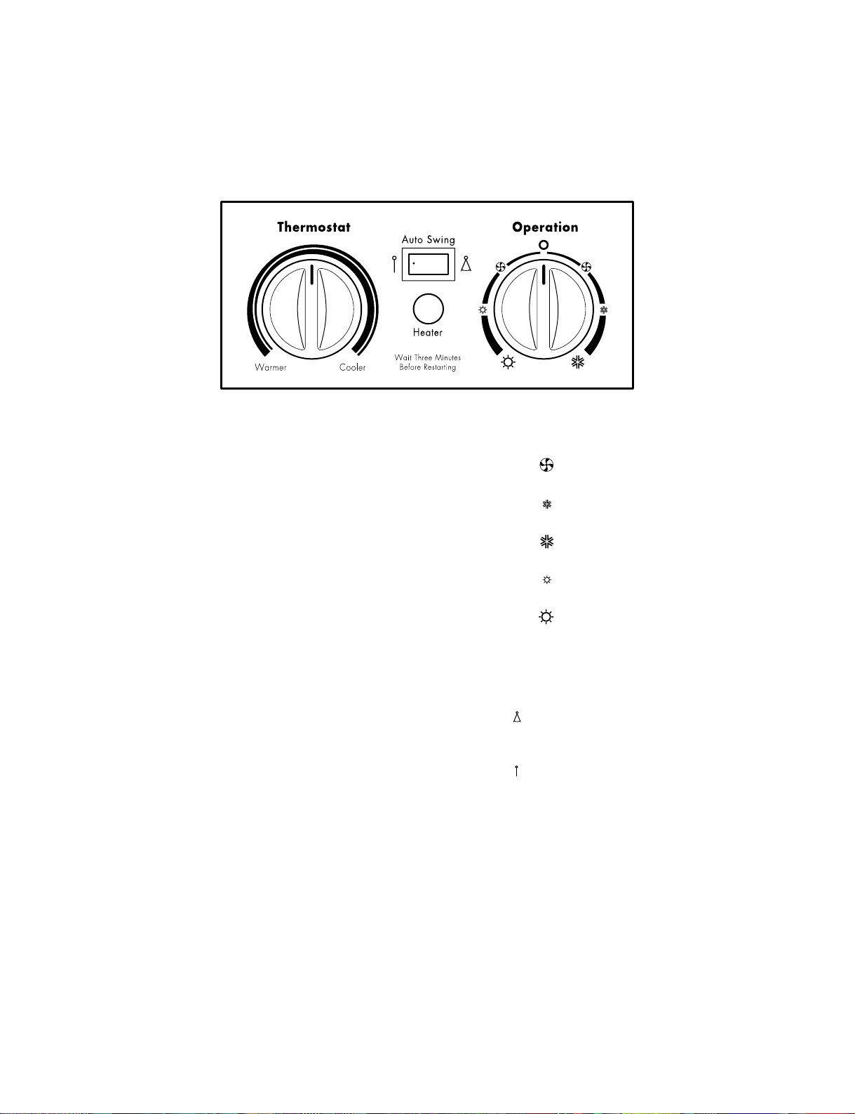
1.5.1 COOLING ONLY MODEL
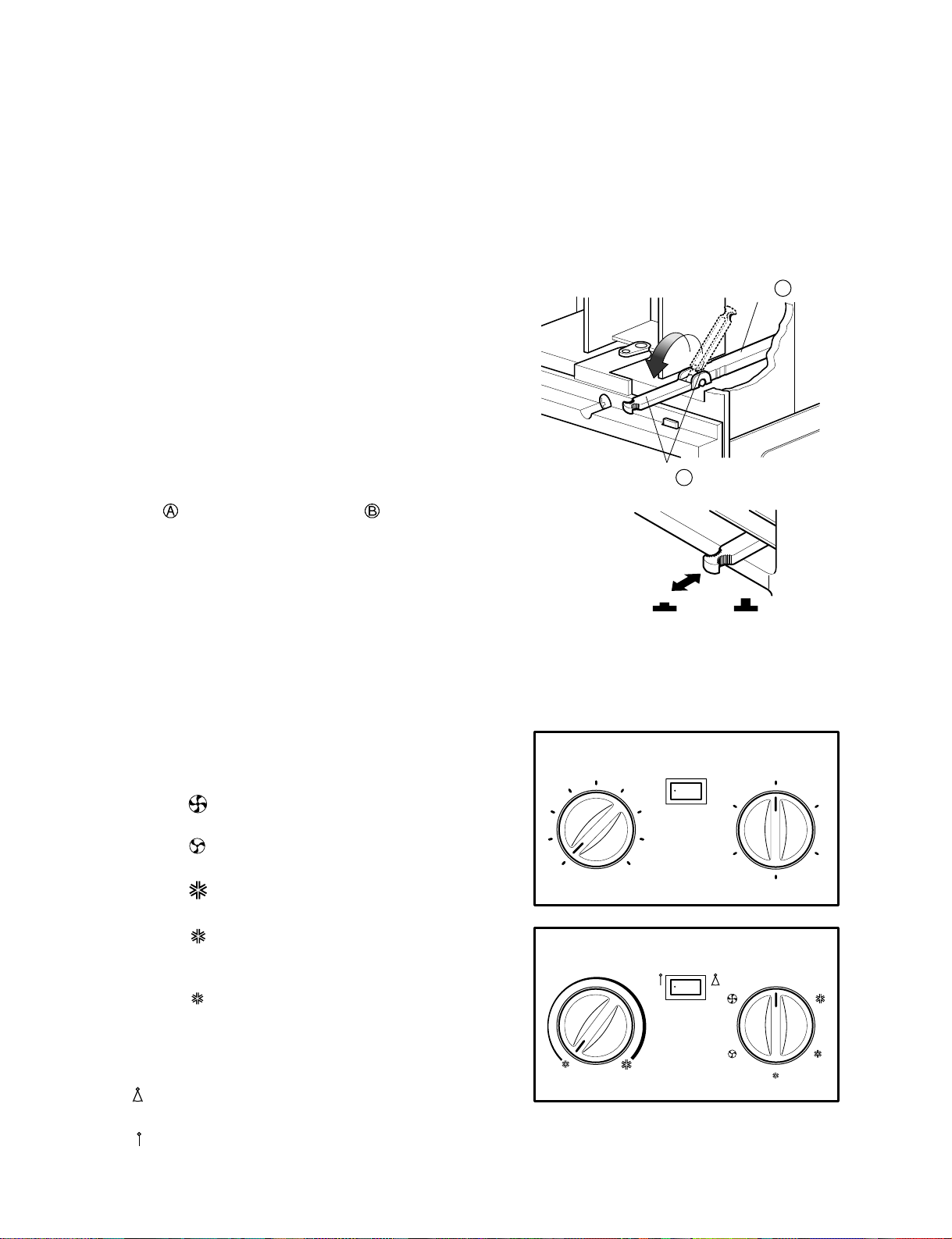
• VENTILATION
The ventilation lever must be in the CLOSE position
in order to maintain the best cooling conditions.
When a fresh air is necessary in the room, set the
ventilation lever to the OPEN position.
The damper is opened and room air is exhausted.
NOTE: Before using the ventilation feature,
make the lever, as shown. First, pull down
part to horizontal line with part .
• THERMOSTAT
Thermostat will automatically control the
temperature of the room. Select the higher number
for the lower temperature of the room. The
temperature is selected by positioning the knob to
the desired position.
The 5 or 6 position is a normal setting for average
conditions.
• OPERATION
O ( ) : Turns the air conditioner off.
MED FAN ( ) : Permits the
medium
fan speed
operation without cooling.
LOW FAN ( ) : Permits the low fan speed
operation without cooling.
HIGH COOL ( ) : Permits cooling with the
high fan speed operation.
MED COOL ( ) : Permits cooling with the
medium fan speed
operation.
LOW COOL ( ) : Permits cooling with the low
fan speed operation.
• AUTO SWING
ON ( ): Air swing is operated while OPERATION
knob is set to the COOL position.
OFF ( ): Stops the operation of air swing.
• Side air-intake, side cooled-air discharge.
• Built in adjustable THERMOSTAT.
• Washable one-touch filter.
• Compact size.
—6—
Part A
Part B
VENTCLOSE OPEN
0
6
7
8
9
5
1
2
Off On
Med
Fan
Off
Low
Fan
High
Cool
Med
Cool
Low Cool
Auto Swing
3
4
Thermostat Operation
0
—7—
1.5.2 HEAT PUMP MODEL
• CAUTION
When the air conditioner has been performing its cooling operation and is turned off or set to the fan position,
wait at least 3 minutes before resetting to the cooling operation again.
• THERMOSTAT
Turn the thermostat control to the desired setting. The
control position is a normal setting for average
conditions. You can change this setting, if necessary, in
accordance with your temperature preference.
The thermostat automatically controls cooling or
heating, but the fan runs continuously whenever the air
conditioner is in operation. If the room is too warm, turn
the thermostat control clockwise. If the room is too cool,
turn the thermostat control counterclockwise.
• HEATER LAMP
When the unit sets heating operation condition, the
green lamp is lighted.
When the frost settles on the heat exchanger of the
outside, defrosting is made automatically and the green
lamp is turned off. The unit may give a hiss and the fan
motor stops for 1 to 10 minutes.
This should not be regarded as a problem.
After defrosting, the heating operation begins again.
• OPERATION
OFF ( O) : Turns the air conditioner off.
LOW FAN ( ) : Permits the low fan speed
operation without cooling (heating).
LOW COOL ( ) : Permits cooling with the low fan
speed operation.
HIGH COOL( ) : Permits cooling with the high fan
speed operation.
LOW HEAT ( ) : Permits heating with the low fan
speed operation.
HIGH HEAT ( ) : Permits heating with the high fan
speed operation.
• AUTO SWING
ON ( ) : Air swing is operated while
OPERATION knob is set to the COOL
or HEAT position.
OFF ( ) : Stops the operation of air swing.
—8—
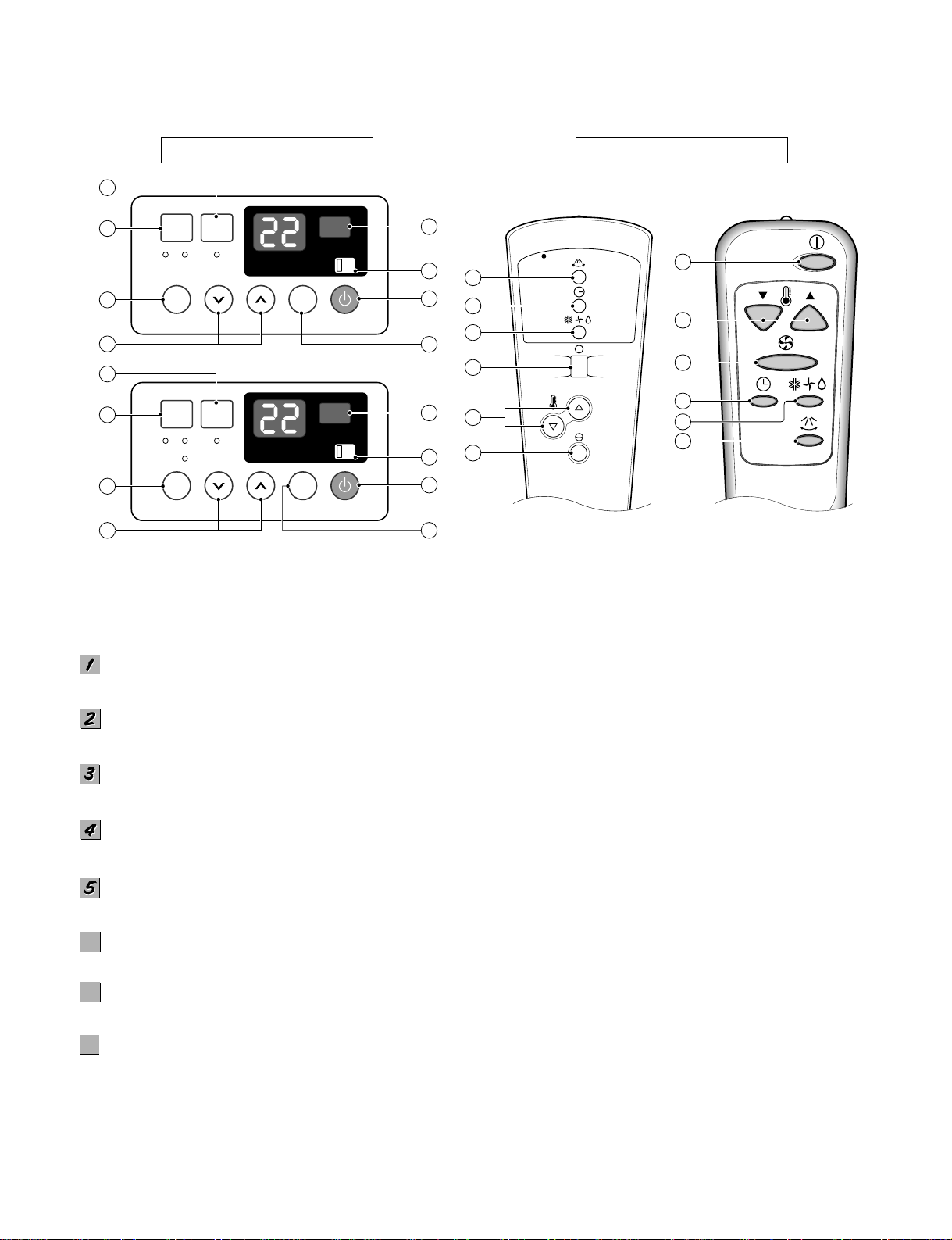
1.5.3 COOLING ONLY MODEL WITH REMOTE CONTROL AND TOUCH TYPE
POWER BUTTON
Operation starts, when this button is pressed and stops when you press the button again.
OPERATION MODE SELECTION BUTTON
Select Cooling, or Fan or Dehumid mode with button. (Dehumid mode is not to all models.)
ON/OFF TIMER BUTTON
Set the time of starting and stopping operation. The timer is set by 1 hour.
FAN SPEED SELECTOR
Everytime you push this button it is set as follows. [High(F3) → Low(F1) → Med(F2) → High(F3)...].
ROOM TEMPERATURE SETTING BUTTON
Control the room temperature within a range of 16°C to 30°C.
AUTO RESTART SWITCH (NOT TO ALL MODELS)
In failure of electric power, if the switch is set to "ON", the unit runs as previous setting operation when power returns.
AUTO SWING BUTTON
Control the horizontal air direcion by air swing system.
SIGNAL RECEIVER
6
6
7
7
8
8
Precaution: The Remote Control unit will not function properly if strong light strikes the sensor window of the air
conditioner or if there are obstacles between the Remote Control unit and the air conditioner.
REMOTE CONTROL
DISPLAY
Fan Speed
Mode Sleep
Temp Auto Swing
Fan Cool On
On
Auto Restart
Off
Power
2
3
1
6
8
4
5 7
Velocidad
Modo
Auto
Apagado
Temp Auto
Deflector
Ventilacion Frio
Deshumedad
Encendido
Si
Re-inicio
Automatico
No
Encendido
2
3
1
6
8
4
5 7
3
2
1
5
4
7
1
5
4
3
2
7
—9—
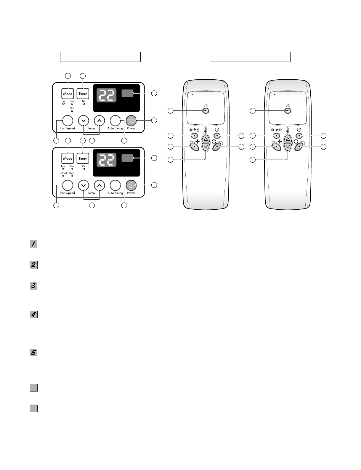
REMOTE CONTROL
DISPLAY
Precaution: The Remote Control unit will not function properly if strong light strikes the sensor window of the air conditioner or
it there are obstacles between the Remote Control unit and the air conditioner.
POWER BUTTON
Operation starts, when this button is pressed and stops when you press the button again.
OPERATION MODE SELECTION BUTTON
Select Cooling, Heating, Fan or Dehumidification(Dry) mode with this button.
ON/OFF TIMER BUTTON
Set the time of starting and stopping operation.
The timer is set by 1 hour.
FAN SPEED SELECTOR
Select the fan speed
- Cooling Model: High[F3] ➔ Low[F1] ➔ Med[F2] ➔ High[F3] ....
- Heating Model: High[F2] ➔ Low[F1] ➔ High[F2] ....
ROOM TEMPERATURE SETTING BUTTON
Control the room temperature within a range of 16°C to 30°C.
The unit takes an average of 30 minutes to adjust the room temperature by 1°C (1.8°F).
Temperature increases only by 2°C and no longer increase thereafter.
AUTO SWING
The vertical louver swings horizontally by the automatic system and stops when you press the button again.
SIGNAL RECEIVER
1
7
5 64
2 3
1
7
5 64
2 3
4
2
6
3
1
5
4
2
6
3
1
5
6
6
7
7
—10—
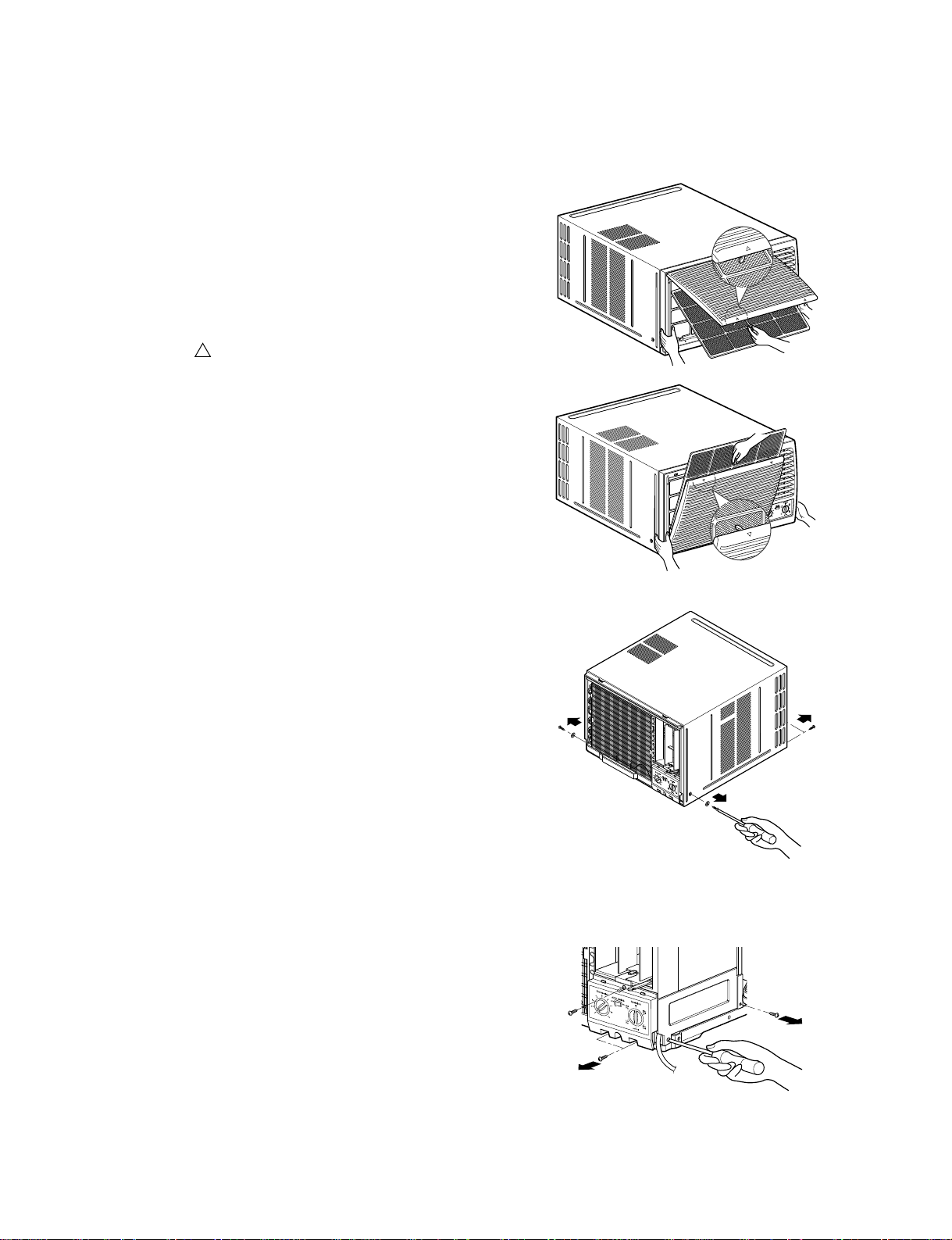
2.1 MECHANICAL PARTS
2.1.1 FRONT GRILLE
1. Open the inlet grille upward or downward.
2. Remove the screw which fastens the front grille.
3. Pull the front grille from the right side.
4. Remove the front grille. (See Fig. 1)
5. Re-install the component by referring to the
removal procedure.
NOTE: Mark " "of inlet grille means opening
direction.
2.1.2 CABINET
1. After disassembling the FRONT GRILLE, remove
the screws which fasten the cabinet at both sides.
2. Remove the two screws which fasten the cabinet
at back. (See Fig. 2)
3. Pull the base pan forward.
2.1.3 CONTROL BOX
1. Remove the front grille. (Refer to section 2.1.1)
2. Pull the base pan forward so that you can remove
the 2 screws which fasten the cover control at the
right side. (See Fig. 3)
3. Remove the 3 screws which fasten the control
box. (See Fig. 3)
4. Discharge the capacitor by placing a 20,000 ohm
resistor across the capacitor terminals.
5. Disconnect two wire housings in the control box.
6. Pull the control box forward completely.
7. Re-install the components by referring to the
removal procedure. (See Fig. 3)
(Refer to the circuit diagram found on page 19 in
this manual and on the control box.)
2. DISASSEMBLY INSTRUCTIONS
— Before the following disassembly, POWER SWITCH is set to OFF and disconnected the power cord.
Figure 1
Figure 2
Figure 3
—11—
2.2 AIR HANDLING PARTS
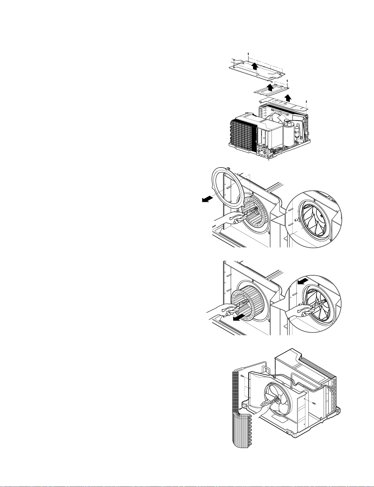
2.2.1 COVER (AT THE TOP)
1. Remove the front grille. (Refer to section 2.1.1)
2. Remove the cabinet. (Refer to section 2.1.2)
3. Remove 11 screws which fasten the brace and
covers.
4. Remove the covers and the brace. (See Fig. 4)
5. Re-install the components by referring to the
removal procedure, above.
2.2.2 BLOWER
1. Remove the cover. (Refer to section 2.2.1)
2. Remove the 3 screws which fasten the evaporator
at the left side and the top side.
3. Move the evaporator sideward carefully.
4. Remove the orifice from the air guide carefully.
5. Remove the clamp which secures the blower with
plier. (See Fig. 5)
6. Remove the blower with plier or your hand without
touching blades. (See Fig. 6)
7. Re-install the components by referring to the
removal procedure, above.
2.2.3 FAN
1. Remove the cabinet. (Refer to section 2.1.2)
2. Remove the brace and shroud cover.
(Refer to section 2.2.1)
3. Remove the 5 screws which fasten the condenser.
4. Move the condenser sideways carefully.
5. Remove the clamp which secures the fan.
6. Remove the fan. (See Fig. 7)
7. Re-install the components by referring to the
removal procedure, above.
Figure 4
Figure 5
Figure 6
Figure 7
—12—
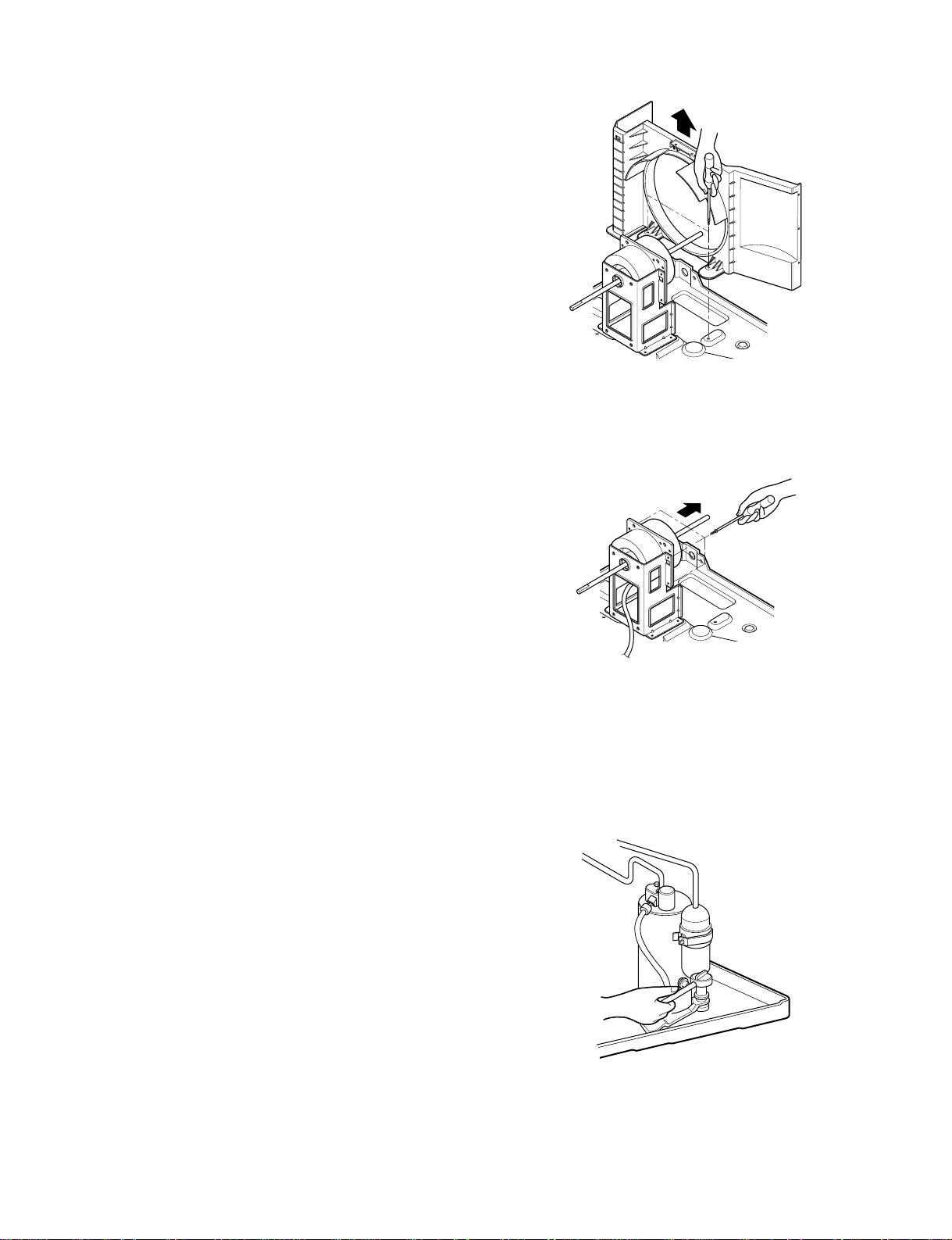
2.2.4 SHROUD
1. Remove the fan. (Refer to section 2.2.3)
2. Remove the 2 screws which fasten the shroud.
3. Remove the shroud. (See Fig. 8)
4. Re-install the component by referring to the
removal procedure, above.
2.3 ELECTRICAL PARTS
2.3.1 MOTOR
1. Remove the cabinet. (Refer to section 2.1.2)
2. Remove the cover control and disconnect a wire
housing in control box. (Refer to section 2.1.3)
3. Remove the blower. (Refer to section 2.2.2)
4. Remove the fan. (Refer to section 2.2.3)
5. Remove the 4 screws which fasten the motor.
(See Fig. 9)
6. Remove the motor.
7. Re-install the components by referring to the
removal procedure, above.
2.3.2 COMPRESSOR
1. Remove the cabinet. (Refer to section 2.1.2)
2. Discharge the refrigerant system using Freon
TM
Recovery System.
If there is no valve to attach the recovery system,
install one (such as a WATCO A-1) before venting
the Freon
TM
. Leave the valve in place after
servicing the system.
3. Disconnect the 3 leads from the compressor.
4. After purging the unit completely, unbrace the
suction and discharge tubes at the compressor
connections.
5. Remove the 3 nuts and the 3 washers which
fasten the compressor.
6. Remove the compressor. (See Fig. 10)
7. Re-instill the components by referring to the
removal procedure, above.
Figure 8
Figure 9
Figure 10
—13—
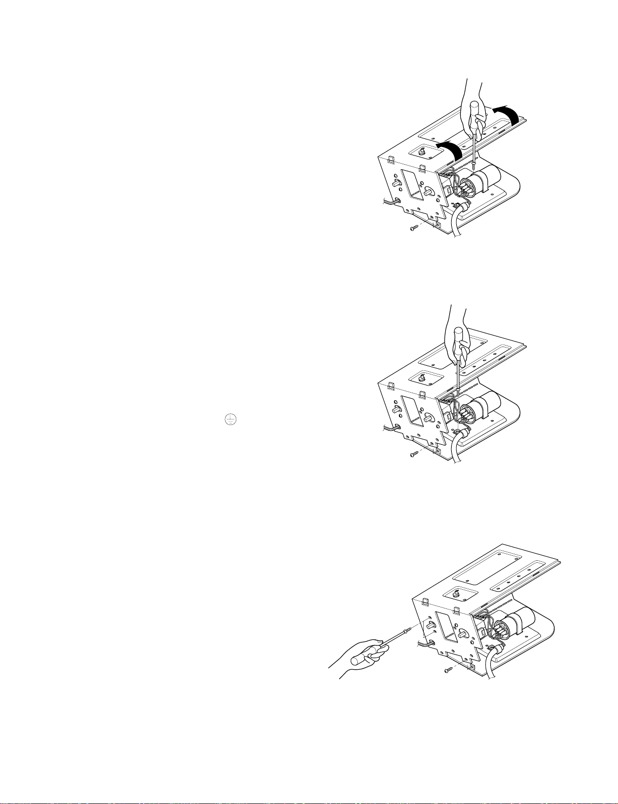
2.3.3 CAPACITOR
1. Remove the control box. (Refer to section 2.1.3)
2. Remove the screw and knobs which fasten the
display panel.
3. Disconnect the 2 leads from the rocker switch and
remove the panel.
4. Remove a screw and unfold the control box.
(See Fig. 11)
5. Remove the screw and the clamp which fastens
the capacitor. (See Fig. 11)
6. Disconnect all the leads of capacitor terminals.
7. Re-install the components by referring to the
removal procedure, above.
2.3.4 POWER CORD
1. Remove the control box. (Refer to section 2.1.3)
2. Unfold the control box. (Refer to section 2.3.3)
3. Disconnect the grounding screw from the control
box.
4. Disconnect 2 receptacles.
5. Remove a screw which fastens the clip cord.
6. Pull the power cord. (See Fig. 12)
7. Re-install the component by referring to the
removal procedure, above.
(Use only one ground-marked hole for ground
connection.)
8. If the supply cord of this appliance is damaged, it
must be replaced by the special cord.
(The special cord means the cord which has the
same specification marked on the supply cord
fitted to the unit.)
2.3.5 THERMOSTAT
1. Remove the control box. (Refer to section 2.1.3)
2. Unfold the control box. (Refer to section 2.3.3)
3. Remove the 2 screws which fasten the thermostat.
4. Disconnect all the leads of thermostat terminals.
5. Remove the thermostat. (See Fig. 13)
6. Re-install the components by referring to the
removal procedure, above.
Figure 12
Figure 11
Figure 13
 Loading...