

Page 1

Room Air Conditioner
SERVICE MANUAL
MODELS: LWM1860BCG/BCL/QCG/QCL/QAG/BAG
LWN1860BCG/BCL/QCG/QCL
LWN2260BCG/BCL/QCG/QCL
LWM1820BCG/BCL/QCG/QCL
LWM1821BCG/BCL/QCG/QCL
LWN2120BCG/BCL/QCG/QCL
LWN2123BCG
LWM1830BCG/BCL/QCG/QCL
LWN2130BCG/BCL/QCG/QCL,BXN
LWN2131BAG
LWM2130AAG/BAG
LWM1860BCP
LWN2120BHG/BHP/QHG
LWN2123BHG
CAUTION
- BEFORE SERVICING THE UNIT, READ THE "SAFETY
PRECAUTIONS" IN THIS MANUAL.
- ONLY FOR AUTHORIZED SERVICE.
website http://biz.LGservice.com
e-mail http://www.LGEservice.com/techsup.html
Page 2

—2—
1. PREFACE
1.1 SAFETY PRECAUTIONS ...............................2
1.2 INSULATION RESISTANCE TEST.................2
1.3 SPECIFICATIONS ..........................................3
1.4 FEATURES.....................................................6
1.5 CONTROL LOCATIONS.................................6
1.5.1 COOLING ONLY MODEL......................6
1.5.2 HEAT PUMP MODEL ............................7
1.5.3
COOLING ONLY MODEL WITH REMOTE
CONTROL AND TOUCH TYPE
.................8
2.
DISASSEMBLY INSTRUCTIONS
2.1 MECHANICAL PARTS..................................10
2.1.1 FRONT GRILLE...................................10
2.1.2 CABINET..............................................10
2.1.3 CONTROL BOX...................................10
2.2 AIR HANDLING PARTS................................11
2.2.1 COVER (AT THE TOP)........................11
2.2.2 BLOWER..............................................11
2.2.3 FAN......................................................11
2.2.4 SHROUD..............................................12
2.3 ELECTRICAL PARTS...................................12
2.3.1 MOTOR................................................12
2.3.2 COMPRESSOR...................................12
2.3.3 CAPACITOR........................................13
2.3.4 POWER CORD....................................13
2.3.5 THERMOSTAT ....................................13
2.3.6 ROTARY SWITCH...............................14
2.3.7 SYNCHRONOUS MOTOR ..................14
2.4 REFRIGERATION CYCLE.................................15
2.4.1 CONDENSER......................................15
2.4.2 EVAPORATOR....................................15
2.4.3 CAPILLARY TUBE...............................15
3.
TROUBLESHOOTING GUIDE
3.1 OUTSIDE DIMENSIONS...............................18
3.2 PIPING SYSTEM ..........................................18
3.3 TROUBLESHOOTING GUIDE......................19
4. SCHEMATIC DIAGRAM
4.1 CIRCUIT DIAGRAM......................................29
4.2 ELECTROING CONTROL DEVICE..............31
4.3 COMPONENTS LOCATION
(OF MAIN P.C.B ASM)..................................32
4.4 COMPONENTS LOCATION
(FOR DISPLAY P.C.B ASM).........................33
5. EXPLODED VIEW..................................34
6. REPLACEMENT PARTS LIST.......36
1. PREFACE
This
SERVICE MANUAL provides various service information, including the mechanical and electrical
parts etc. This room air conditioner was manufactured and assembled under a strict quality control system.
The refrigerant is charged at the factory. Be sure to read the safety precautions prior to servicing the unit.
1.1 SAFETY PRECAUTIONS
1. When servicing the unit, set the ROTARY SWITCH
or POWER SWITCH to OFF and unplug the power
cord.
2. Observe the original lead dress.
If a short circuit is found, replace all parts which
have been overheated or damaged by the short
circuit.
3. After servicing the unit, make an insulation
resistance test to protect the customer from being
exposed to shock hazards.
1.2
INSULATION RESISTANCE TEST
1. Unplug the power cord and connect a jumper
between 2 pins (black and white).
2. The grounding conductor (green or green & yellow)
is to be open.
3. Measure the resistance value with an ohm meter
between the jumpered lead and each exposed
metallic part on the equipment at all the positions
(except OFF or O) of the ROTARY SWITCH.
4. The value should be over 1MΩ.
CONTENTS
Page 3
—3—
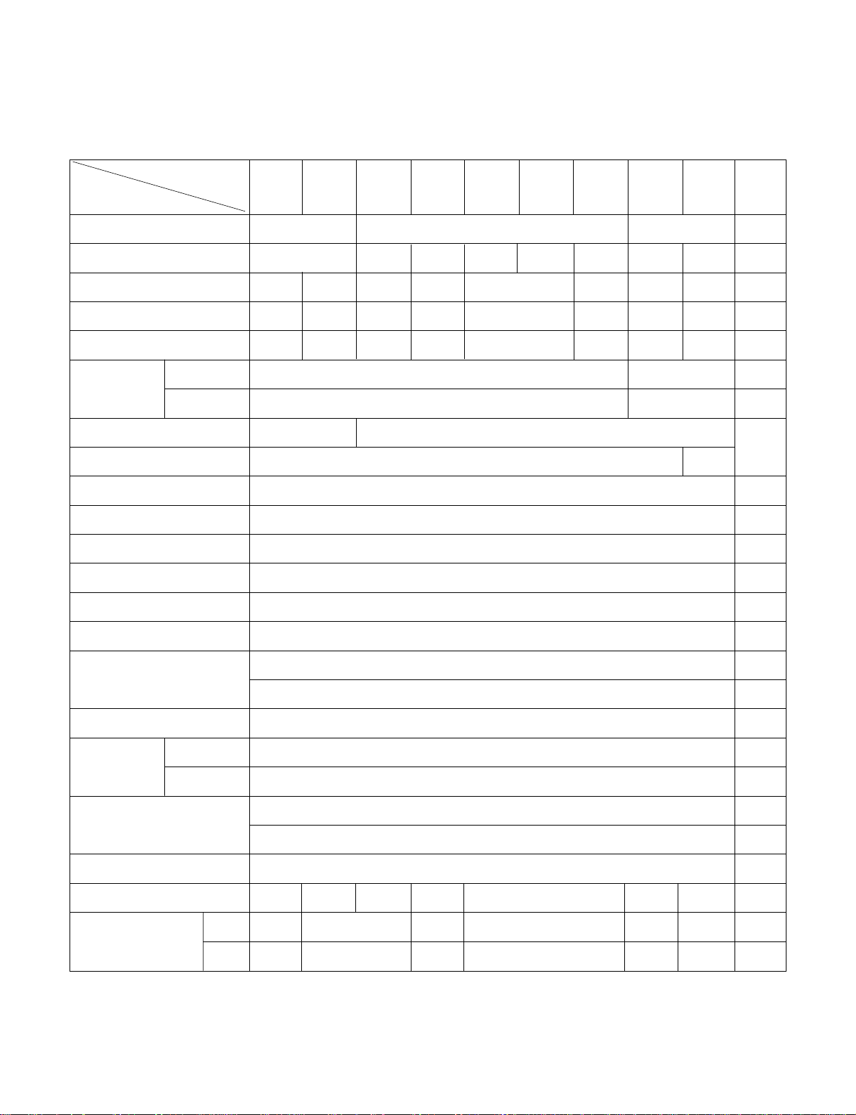
1.3 SPECIFICATIONS
1.3.1 FOR
LWM1860BCG(BCL)/LWN1860BCG(BCL)/LWN2260BCG(BCL)/LWM1820BCG(BCL)LWM1821BCG(BCL)
LWN2120BCG(BCL)/LWM1830BCG(BCL)/LWN2130BCG(BCL)/LWN2123BCG/BAG / LWM2130AAG/BAG
POWER SUPPLY
COOLING CAPACITY
INPUT (W)
RUNNING CURRENT (A)
REFRIGERANT (R-22) CHARGE(g)
INDOOR (°C)
OUTDOOR (°C)
EVAPORATOR
CONDENSER
FAN, INDOOR
FAN, OUTDOOR
FAN SPEEDS, FAN/COOLING
FAN MOTOR
OPERATION CONTROL
ROOM TEMP. CONTROL
CONSTRUCTION
COMPRESSOR
FAN MOTOR
DRAIN SYSTEM
NET WEIGHT (lbs/kg)
OUTSIDE DIMENSION
(inch)
(W x H x D) (mm)
LWM1860
BCG(BCL)
BAG/BCP
LWN1860
BCG
(BCL)
LWN2260
BCG
(BCL)
LWN1820/1
BCG
(BCL)
LWN2120
BCG
(BCL)
LWN2123
BCG
LWM2130
AAG/
BAG
LWN1830
BCG
(BCL)
LWN2130
BCG(BCL)
LWN2131BAG
REMARK
1Ø, 220-240V, 50Hz 1Ø, 220V, 60Hz 1Ø, 208-230V, 60Hz
17,500/18,000
21,500/22,000
18,000 21,000 24,000 22,000 18,000 21,000
2,035/2,100 2,190/2250 2,810/2,890 2,090/2,000
2,440 2,470 2,000 2,470
9.3/8.6 10.6/10.1 13.5/12.8 9.8/9.0 11.5 10.8 9.0 12
690 610 600 630 700 710 740 1,090
27(DB), 19(WB) 26.55(DB), 19.35(WB)
35(DB), 24(WB) 34.85(DB), 23.75(WB)
2 ROW 15 STACKS 3 ROW 15 STACKS
BLOWER
PROPELLER TYPE FAN WITH SLINGER-RING
2/3
6 POLES
ROTARY SWITCH
THERMOSTAT
VERTICAL LOUVER(RIGHT & LEFT)
HORIZONTAL LOUVER(UP & DOWN)
SLIDE IN-OUT CHASSIS
INTERNAL OVERLOAD PROTECTOR
INTERNAL THERMAL PROTECTOR
1.6m (3 WIRE WITH GROUNDING)
CORD-CONNECTED TYPE (ATTACHMENT PLUG: OPTION)
DRAIN PIPE OR SPLASHED BY FAN SLINGER
132/60 143/65 148/67 121/55 148/67 121/55 143/65
26 x 16
27
/32
x 26
9
/16
26 x 16
27
/32
x 30
5
/16
26 x 16
27
/32
x 26
9
/16
26 x 16
27
/32
x 30
5
/16
26 x 16
27
/32
x 26
9
/16
26 x 16
27
/32
x 30
5
/16
660 x 428 x 675 660 x 428 x 770 660 x 428 x 675 660 x 428 x 770 660 x 428 x 675 660 x 428 x 770
MODELS
ITEMS
AIR DIRECTION CONTROL
PROTECTOR
POWER CORD
OPERATING
TEMPERATURE
2 ROW 19 STACKS, L-BENDED TYPE
2 ROW 16 STACKS,
L-BENDING TYPE
Page 4
—4—
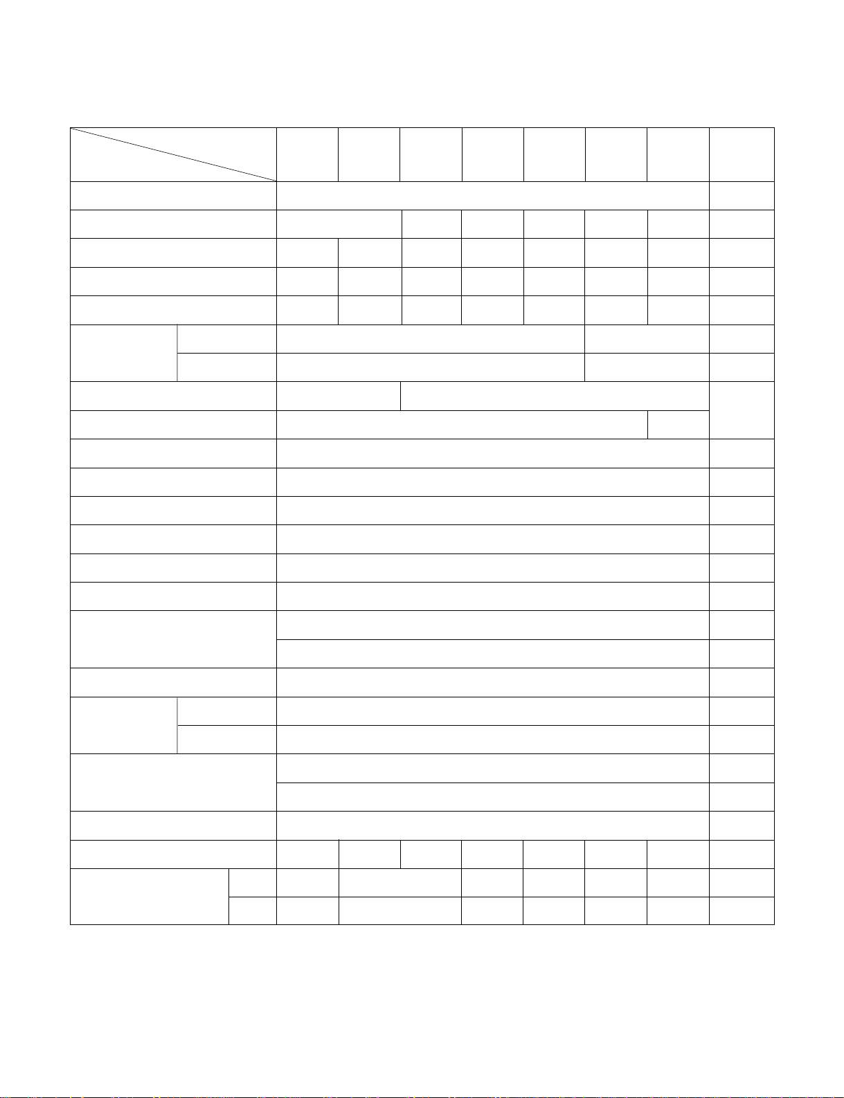
1.3.2 FOR
LWM1860QCG(QCL, QAG)/LWN1860QCG(QCL)/LWN2260QCG(QCL)/LWM1820QCG(QCL)
LWM1821QCG(QCL)/LWN2120QCG(QCL)/LWM1830QCG(QCL)/LWN2130QCG(QCL)
POWER SUPPLY
COOLING CAPACITY
INPUT (W)
RUNNING CURRENT (A)
REFRIGERANT (R-22) CHARGE(g)
INDOOR (°C)
OUTDOOR (°C)
EVAPORATOR
CONDENSER
FAN, INDOOR
FAN, OUTDOOR
FAN SPEEDS, FAN/COOLING
FAN MOTOR
OPERATION CONTROL
ROOM TEMP. CONTROL
CONSTRUCTION
COMPRESSOR
FAN MOTOR
DRAIN SYSTEM
NET WEIGHT (lbs/kg)
OUTSIDE DIMENSION (inch)
(W x H x D) (mm)
1Ø, 220-240V, 50Hz 1Ø, 220V, 60Hz
17,500/18,000 21,500/22,000 18,000 21,000 18,000 21,000
2,035/2,100 2,190/2,250 2,810/2,890 2,090/2,000 2,440 2,000 2,470
9.3/8.6 10.6/10.1 13.5/12.8 9.8/9.0 11.5 9.0 12
690 610 600 630 700 740 1,090
27(DB), 19(WB)
35(DB), 24(WB)
BLOWER
PROPELLER TYPE FAN WITH SLINGER-RING
2/2
6 POLES
WIRELESS REMOCON
THERMISTOR
VERTICAL LOUVER(RIGHT & LEFT)
HORIZONTAL LOUVER(UP & DOWN)
SLIDE IN-OUT CHASSIS
INTERNAL OVERLOAD PROTECTOR
INTERNAL THERMAL PROTECTOR
1.6m (3 WIRE WITH GROUNDING)
CORD-CONNECTED TYPE (ATTACHMENT PLUG: OPTION)
DRAIN PIPE OR SPLASHED BY FAN SLINGER
132/60 143/65 148/67 121/55 148/67 121/55 143/65
26 x 16
27
/32 x 269/16 26 x 1627/32 x 305/16 26 x 1627/32 x 269/16 26 x 1627/32 x 305/16 26 x 1627/32 x 269/16 26 x 1627/32 x 30
5
/16
660 x 428 x 675 660 x 428 x 770 660 x 428 x 675 660 x 428 x 770 660 x 428 x 675 660 x 428 x 770
MODELS
ITEMS
AIR DIRECTION CONTROL
PROTECTOR
POWER CORD
OPERATING
TEMPERATURE
REMARK
LWM1860
QCG
(QCL, QAG)
LWN1860
QCG(QCL)
LWN2260
QCG(QCL)
LWM1820/1
QCG(QCL)
LWN2120
QCG(QCL)
LWM1830
QCG(QCL)
LWN2130
QCG(QCL)
2 ROW 19 STACKS, L-BENDED TYPE
2 ROW 16 STACKS,
L-BENDING TYPE
2 ROW 15 STACKS
3 ROW 15 STACKS
26.55(DB), 19.35(WB)
34.85(DB), 23.75(WB)
Page 5
—5—
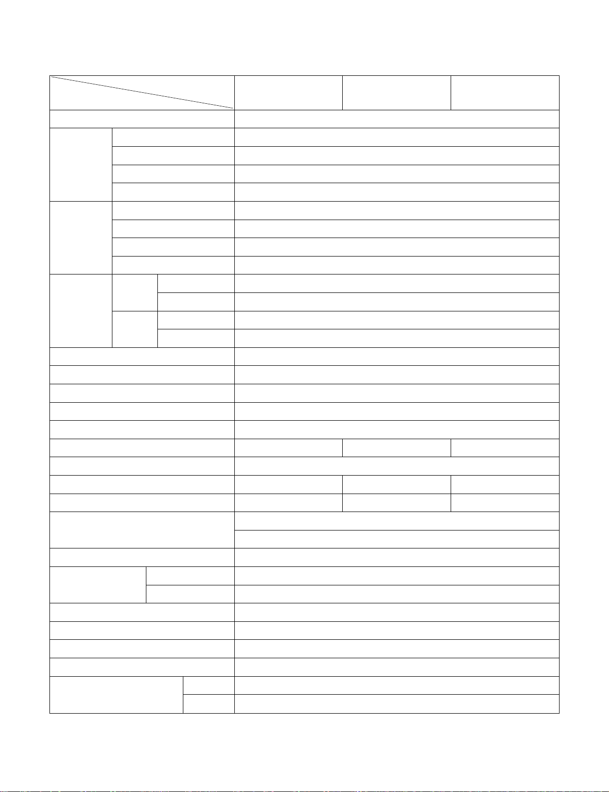
1.3.3 FOR LWN2120BHG/BHP/QHG, LWN2123BHG
LWN2120BHG/BHP LWN2120QHG LWN2123BHG
POWER SUPPLY
CAPACITY (BTU/H)
COOLING
INPUT (W)
RUNNING CURRENT(A)
E.E.R (BTU/W.h)
CAPACITY (BTU/h)
HEATING
INPUT (W)
RUNNING CURRENT(A)
E.E.R (BTU/W.h)
COOLING
INDOOR (°C)
OUTDOOR (°C)
HEATING
INDOOR (°C)
OUTDOOR (°C)
REFRIGERANT (R-22) CHARGE
EVAPORATOR
CONDENSER
FAN, INDOOR
FAN, OUTDOOR
FAN SPEEDS, FAN/COOLING/HEATING
FAN MOTOR
OPERATION CONTROL
ROOM TEMP. CONTROL
AIR DIRECTION CONTROL
CONSTRUCTION
PROTECTOR COMPRESSOR
FAN MOTOR
POWER CORD
DRAIN SYSTEM
NET WEIGHT (lbs/kg)
OUTSIDE DIMENSION (inch)
(W X H X D) (mm)
1ø, 220V, 60Hz
24,000
2,560
12.3
-
24,000
2,560
12.3
9.4
27 (DB)* 19 (WB)**
35 (DB) 24 (WB)
20 (DB) 15 (WB)
7 (DB) 6 (WB)
1200g (42.3 Oz)
3ROW 15STACKS, LOUVERED-FIN TYPE
2ROW 16STACKS, LOUVERED-FIN TYPE
TURBO FAN
PROPELLER TYPE FAN WITH SLINGER-RING
1/2/2 2/2/2 1/2/2
6 POLES
ROTARY SWITCH WIRELESS REMOCON ROTARY SWITCH
THERMOSTAT THERMISTOR THERMOSTAT
VERTICAL LOUVER (RIGHT & LEFT)
HORIZONTAL LOUVER (UP & DOWN)
SLIDE IN-OUT CHASSIS
OVERLOAD PROTECTOR
INTERNAL THERMAL PROTECTOR
1.8m (7") (3 WIRE WITH GROUDING)
ATTACHMENT PLUG (CORD-CONNECTED TYPE)
DRAIN PAN OR SPLASHED BY FAN SLINGER
147.7(67)
23 x 1627/32 x305/16
660 x 428 x 770
MODELS
ITEMS
OPERATING
TEMPERATURE
* DB : dry bulb
** WB : wet bulb
Page 6
1.4 FEATURES
• Designed for cooling only.
• Powerful and quiet cooling.
• Slide-in and slide-out chassis for the simple
installation and service.
• Reversible inlet grille.
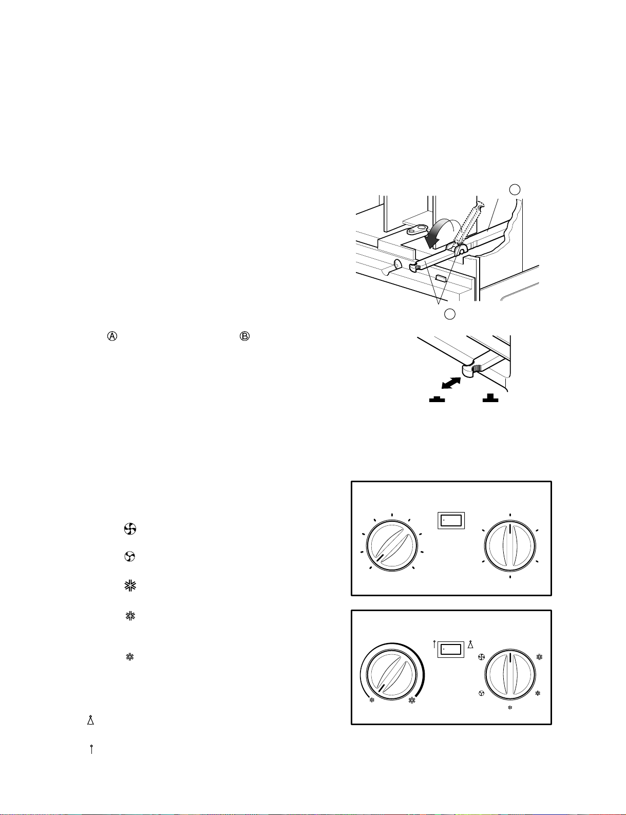
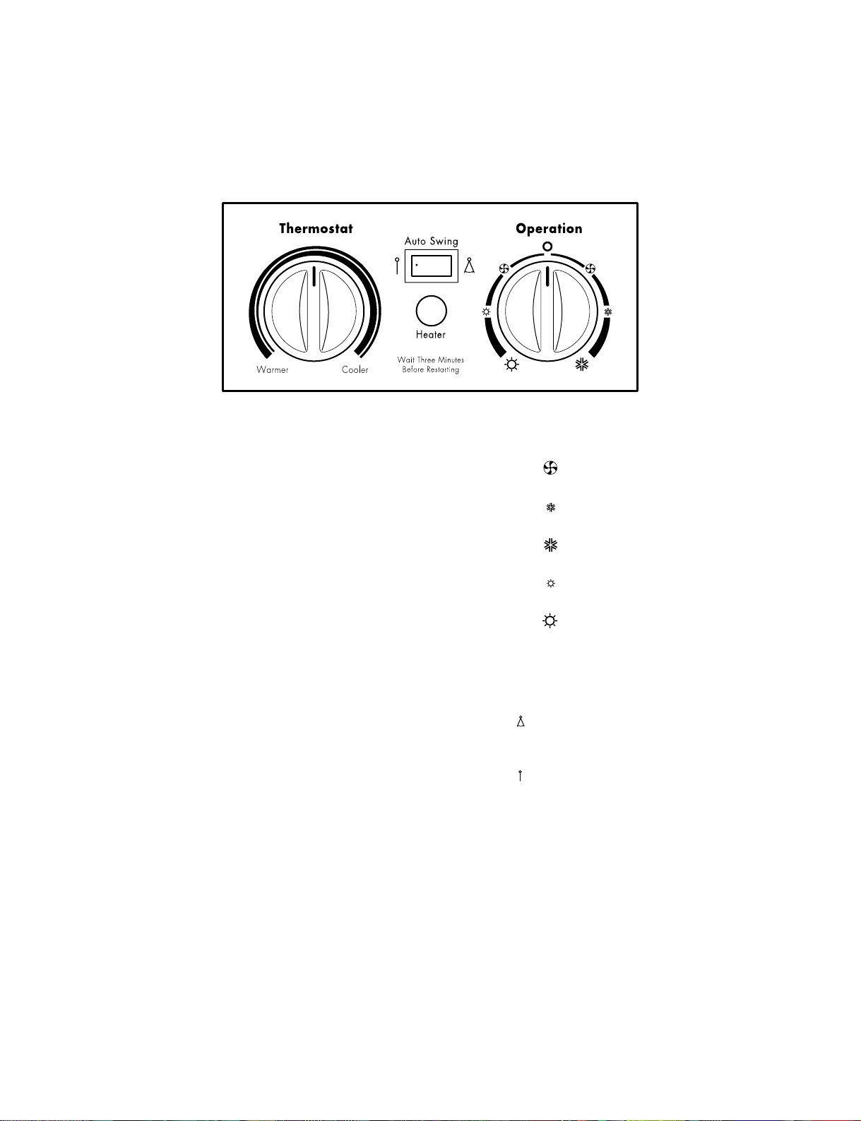
1.5 CONTROL LOCATIONS
1.5.1 COOLING ONLY MODEL
• VENTILATION
The ventilation lever must be in the CLOSE position
in order to maintain the best cooling conditions.
When a fresh air is necessary in the room, set the
ventilation lever to the OPEN position.
The damper is opened and room air is exhausted.
NOTE: Before using the ventilation feature,
make the lever, as shown. First, pull down
part to horizontal line with part .
• THERMOSTAT
Thermostat will automatically control the
temperature of the room. Select the higher number
for the lower temperature of the room. The
temperature is selected by positioning the knob to
the desired position.
The 5 or 6 position is a normal setting for average
conditions.
• OPERATION
O ( ) : Turns the air conditioner off.
MED FAN ( ) : Permits the
medium
fan speed
operation without cooling.
LOW FAN ( ) : Permits the low fan speed
operation without cooling.
HIGH COOL ( ) : Permits cooling with the
high fan speed operation.
MED COOL ( ) : Permits cooling with the
medium fan speed
operation.
LOW COOL ( ) : Permits cooling with the low
fan speed operation.
• AUTO SWING
ON ( ): Air swing is operated while OPERATION
knob is set to the COOL position.
OFF ( ): Stops the operation of air swing.
• Side air-intake, side cooled-air discharge.
• Built in adjustable THERMOSTAT.
• Washable one-touch filter.
• Compact size.
—6—
Part A
Part B
VENTCLOSE OPEN
0
6
7
8
9
5
1
2
Off On
Med
Fan
Off
Low
Fan
High
Cool
Med
Cool
Low Cool
Auto Swing
3
4
Thermostat Operation
0
Page 7
—7—
1.5.2 HEAT PUMP MODEL
• CAUTION
When the air conditioner has been performing its cooling operation and is turned off or set to the fan position,
wait at least 3 minutes before resetting to the cooling operation again.
• THERMOSTAT
Turn the thermostat control to the desired setting. The
control position is a normal setting for average
conditions. You can change this setting, if necessary, in
accordance with your temperature preference.
The thermostat automatically controls cooling or
heating, but the fan runs continuously whenever the air
conditioner is in operation. If the room is too warm, turn
the thermostat control clockwise. If the room is too cool,
turn the thermostat control counterclockwise.
• HEATER LAMP
When the unit sets heating operation condition, the
green lamp is lighted.
When the frost settles on the heat exchanger of the
outside, defrosting is made automatically and the green
lamp is turned off. The unit may give a hiss and the fan
motor stops for 1 to 10 minutes.
This should not be regarded as a problem.
After defrosting, the heating operation begins again.
• OPERATION
OFF ( O) : Turns the air conditioner off.
LOW FAN ( ) : Permits the low fan speed
operation without cooling (heating).
LOW COOL ( ) : Permits cooling with the low fan
speed operation.
HIGH COOL( ) : Permits cooling with the high fan
speed operation.
LOW HEAT ( ) : Permits heating with the low fan
speed operation.
HIGH HEAT ( ) : Permits heating with the high fan
speed operation.
• AUTO SWING
ON ( ) : Air swing is operated while
OPERATION knob is set to the COOL
or HEAT position.
OFF ( ) : Stops the operation of air swing.
Page 8
—8—
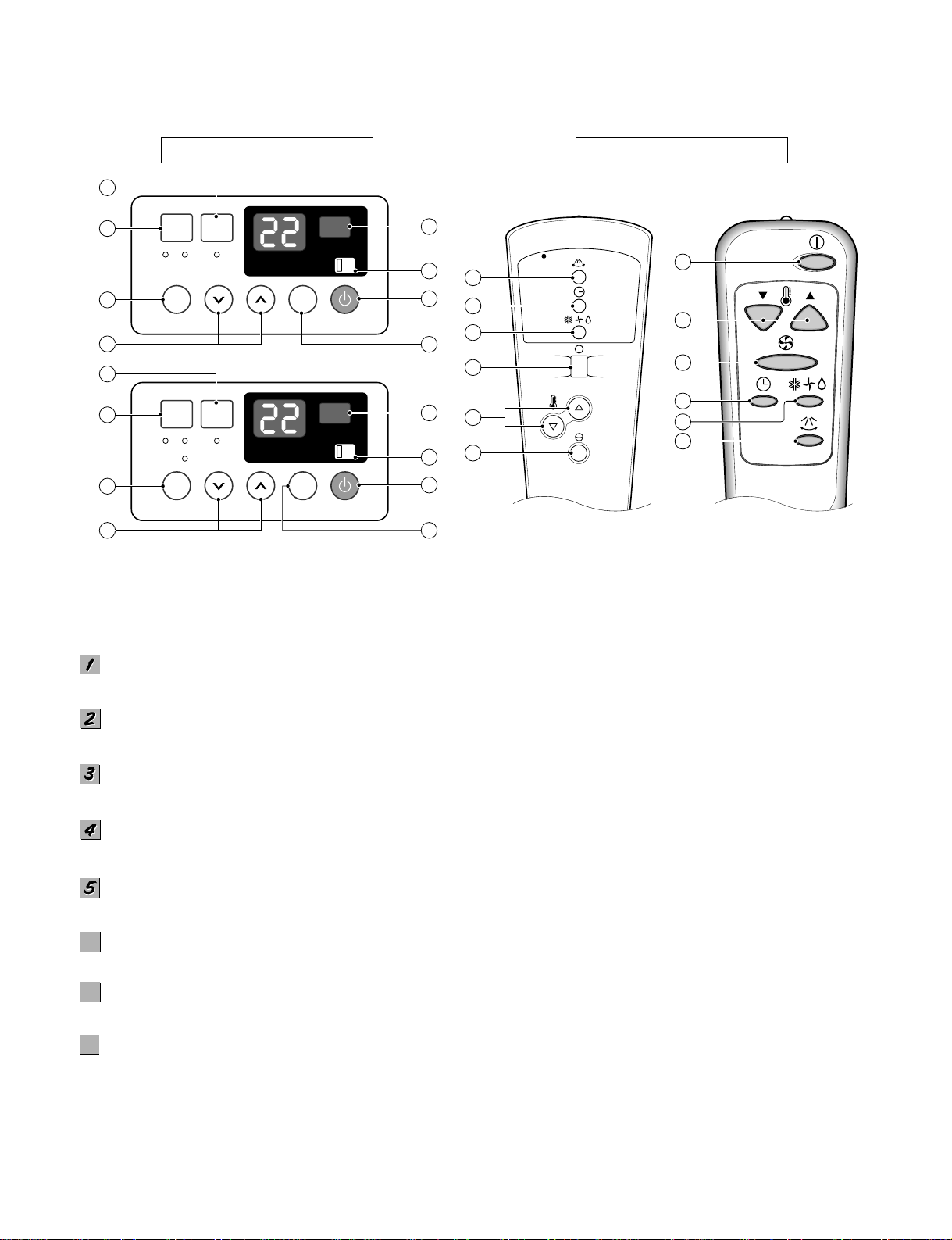
1.5.3 COOLING ONLY MODEL WITH REMOTE CONTROL AND TOUCH TYPE
POWER BUTTON
Operation starts, when this button is pressed and stops when you press the button again.
OPERATION MODE SELECTION BUTTON
Select Cooling, or Fan or Dehumid mode with button. (Dehumid mode is not to all models.)
ON/OFF TIMER BUTTON
Set the time of starting and stopping operation. The timer is set by 1 hour.
FAN SPEED SELECTOR
Everytime you push this button it is set as follows. [High(F3) → Low(F1) → Med(F2) → High(F3)...].
ROOM TEMPERATURE SETTING BUTTON
Control the room temperature within a range of 16°C to 30°C.
AUTO RESTART SWITCH (NOT TO ALL MODELS)
In failure of electric power, if the switch is set to "ON", the unit runs as previous setting operation when power returns.
AUTO SWING BUTTON
Control the horizontal air direcion by air swing system.
SIGNAL RECEIVER
6
6
7
7
8
8
Precaution: The Remote Control unit will not function properly if strong light strikes the sensor window of the air
conditioner or if there are obstacles between the Remote Control unit and the air conditioner.
REMOTE CONTROL
DISPLAY
Fan Speed
Mode Sleep
Temp Auto Swing
Fan Cool On
On
Auto Restart
Off
Power
2
3
1
6
8
4
5 7
Velocidad
Modo
Auto
Apagado
Temp Auto
Deflector
Ventilacion Frio
Deshumedad
Encendido
Si
Re-inicio
Automatico
No
Encendido
2
3
1
6
8
4
5 7
3
2
1
5
4
7
1
5
4
3
2
7
Page 9
—9—
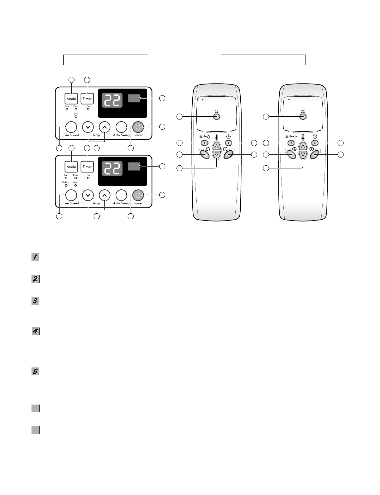
REMOTE CONTROL
DISPLAY
Precaution: The Remote Control unit will not function properly if strong light strikes the sensor window of the air conditioner or
it there are obstacles between the Remote Control unit and the air conditioner.
POWER BUTTON
Operation starts, when this button is pressed and stops when you press the button again.
OPERATION MODE SELECTION BUTTON
Select Cooling, Heating, Fan or Dehumidification(Dry) mode with this button.
ON/OFF TIMER BUTTON
Set the time of starting and stopping operation.
The timer is set by 1 hour.
FAN SPEED SELECTOR
Select the fan speed
- Cooling Model: High[F3] ➔ Low[F1] ➔ Med[F2] ➔ High[F3] ....
- Heating Model: High[F2] ➔ Low[F1] ➔ High[F2] ....
ROOM TEMPERATURE SETTING BUTTON
Control the room temperature within a range of 16°C to 30°C.
The unit takes an average of 30 minutes to adjust the room temperature by 1°C (1.8°F).
Temperature increases only by 2°C and no longer increase thereafter.
AUTO SWING
The vertical louver swings horizontally by the automatic system and stops when you press the button again.
SIGNAL RECEIVER
1
7
5 64
2 3
1
7
5 64
2 3
4
2
6
3
1
5
4
2
6
3
1
5
6
6
7
7
Page 10
—10—
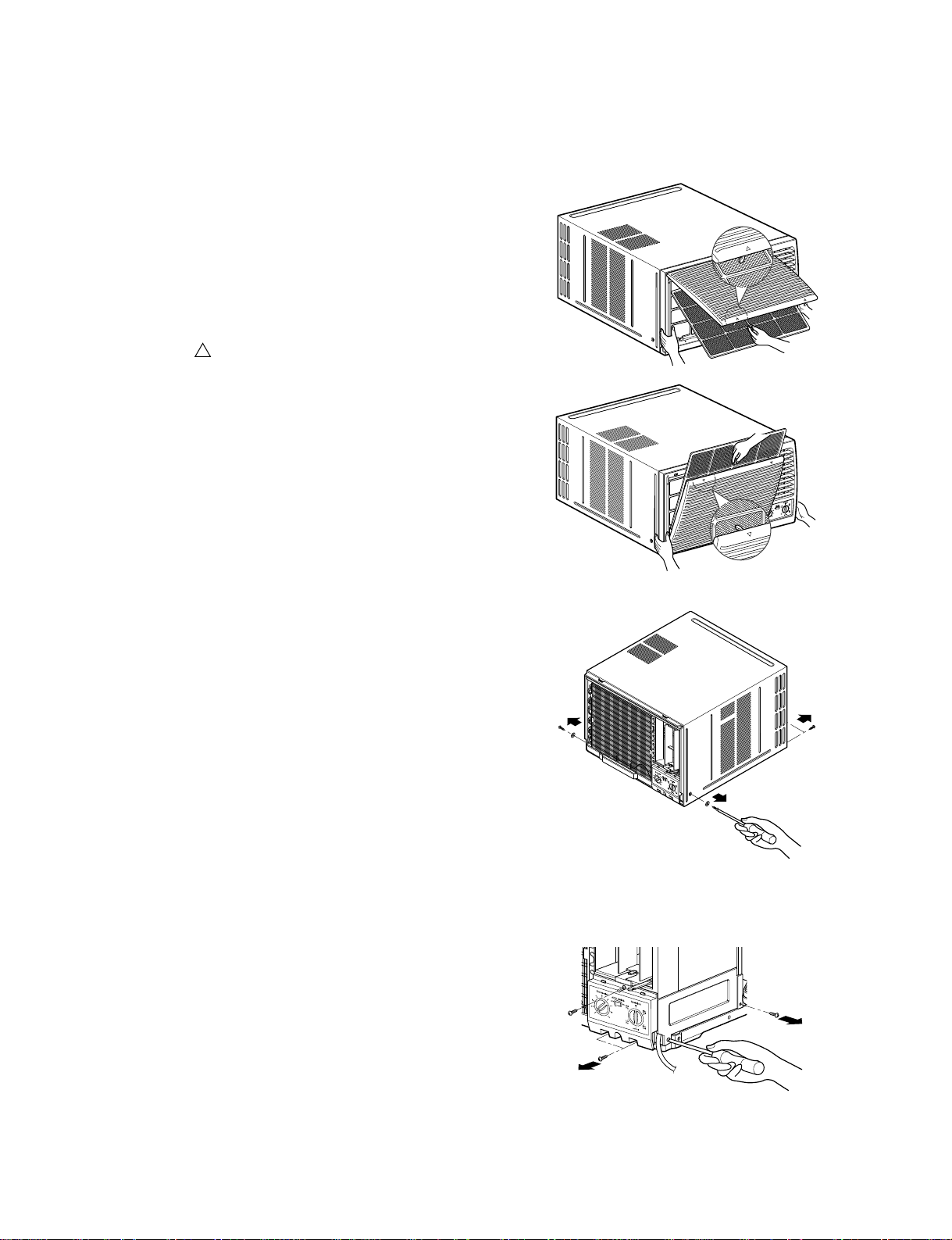
2.1 MECHANICAL PARTS
2.1.1 FRONT GRILLE
1. Open the inlet grille upward or downward.
2. Remove the screw which fastens the front grille.
3. Pull the front grille from the right side.
4. Remove the front grille. (See Fig. 1)
5. Re-install the component by referring to the
removal procedure.
NOTE: Mark " "of inlet grille means opening
direction.
2.1.2 CABINET
1. After disassembling the FRONT GRILLE, remove
the screws which fasten the cabinet at both sides.
2. Remove the two screws which fasten the cabinet
at back. (See Fig. 2)
3. Pull the base pan forward.
2.1.3 CONTROL BOX
1. Remove the front grille. (Refer to section 2.1.1)
2. Pull the base pan forward so that you can remove
the 2 screws which fasten the cover control at the
right side. (See Fig. 3)
3. Remove the 3 screws which fasten the control
box. (See Fig. 3)
4. Discharge the capacitor by placing a 20,000 ohm
resistor across the capacitor terminals.
5. Disconnect two wire housings in the control box.
6. Pull the control box forward completely.
7. Re-install the components by referring to the
removal procedure. (See Fig. 3)
(Refer to the circuit diagram found on page 19 in
this manual and on the control box.)
2. DISASSEMBLY INSTRUCTIONS
— Before the following disassembly, POWER SWITCH is set to OFF and disconnected the power cord.
Figure 1
Figure 2
Figure 3
Page 11
—11—
2.2 AIR HANDLING PARTS
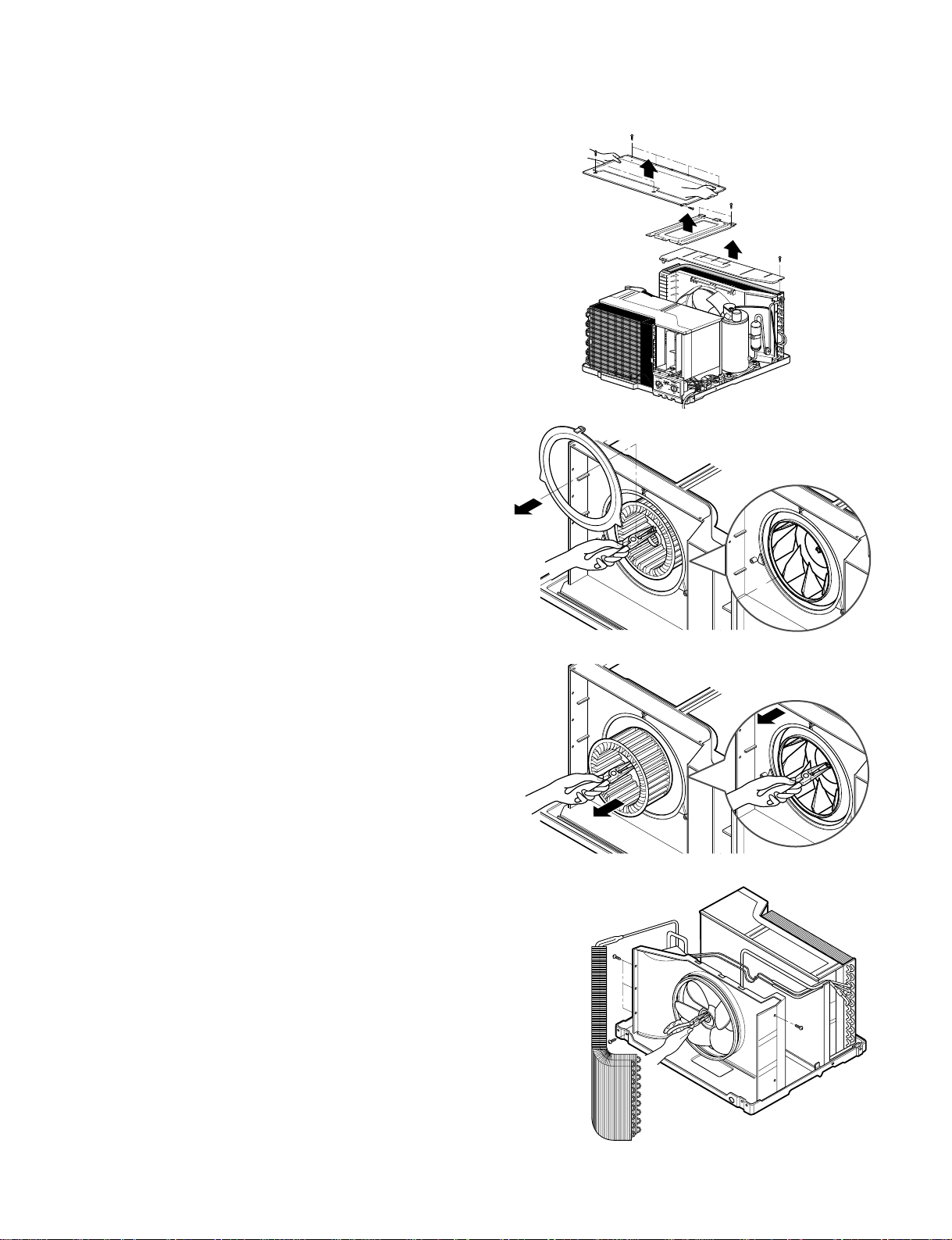
2.2.1 COVER (AT THE TOP)
1. Remove the front grille. (Refer to section 2.1.1)
2. Remove the cabinet. (Refer to section 2.1.2)
3. Remove 11 screws which fasten the brace and
covers.
4. Remove the covers and the brace. (See Fig. 4)
5. Re-install the components by referring to the
removal procedure, above.
2.2.2 BLOWER
1. Remove the cover. (Refer to section 2.2.1)
2. Remove the 3 screws which fasten the evaporator
at the left side and the top side.
3. Move the evaporator sideward carefully.
4. Remove the orifice from the air guide carefully.
5. Remove the clamp which secures the blower with
plier. (See Fig. 5)
6. Remove the blower with plier or your hand without
touching blades. (See Fig. 6)
7. Re-install the components by referring to the
removal procedure, above.
2.2.3 FAN
1. Remove the cabinet. (Refer to section 2.1.2)
2. Remove the brace and shroud cover.
(Refer to section 2.2.1)
3. Remove the 5 screws which fasten the condenser.
4. Move the condenser sideways carefully.
5. Remove the clamp which secures the fan.
6. Remove the fan. (See Fig. 7)
7. Re-install the components by referring to the
removal procedure, above.
Figure 4
Figure 5
Figure 6
Figure 7
Page 12
—12—
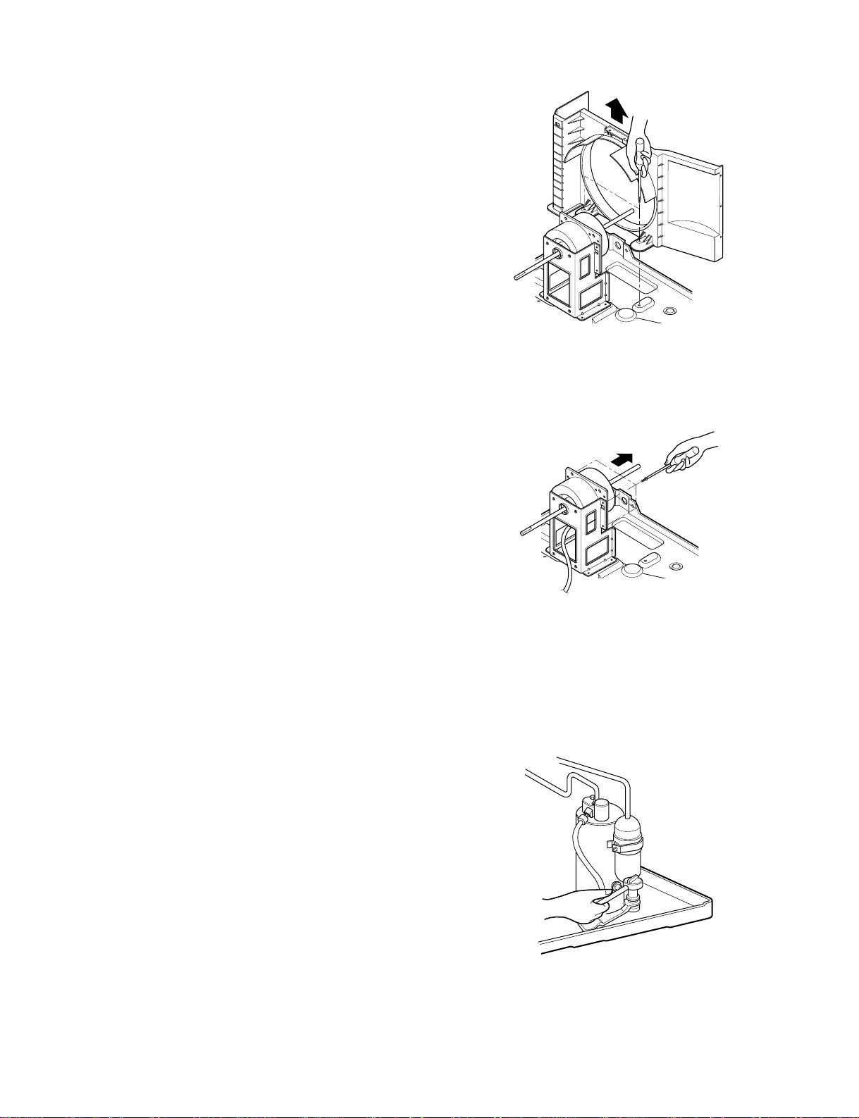
2.2.4 SHROUD
1. Remove the fan. (Refer to section 2.2.3)
2. Remove the 2 screws which fasten the shroud.
3. Remove the shroud. (See Fig. 8)
4. Re-install the component by referring to the
removal procedure, above.
2.3 ELECTRICAL PARTS
2.3.1 MOTOR
1. Remove the cabinet. (Refer to section 2.1.2)
2. Remove the cover control and disconnect a wire
housing in control box. (Refer to section 2.1.3)
3. Remove the blower. (Refer to section 2.2.2)
4. Remove the fan. (Refer to section 2.2.3)
5. Remove the 4 screws which fasten the motor.
(See Fig. 9)
6. Remove the motor.
7. Re-install the components by referring to the
removal procedure, above.
2.3.2 COMPRESSOR
1. Remove the cabinet. (Refer to section 2.1.2)
2. Discharge the refrigerant system using Freon
TM
Recovery System.
If there is no valve to attach the recovery system,
install one (such as a WATCO A-1) before venting
the Freon
TM
. Leave the valve in place after
servicing the system.
3. Disconnect the 3 leads from the compressor.
4. After purging the unit completely, unbrace the
suction and discharge tubes at the compressor
connections.
5. Remove the 3 nuts and the 3 washers which
fasten the compressor.
6. Remove the compressor. (See Fig. 10)
7. Re-instill the components by referring to the
removal procedure, above.
Figure 8
Figure 9
Figure 10
Page 13
—13—
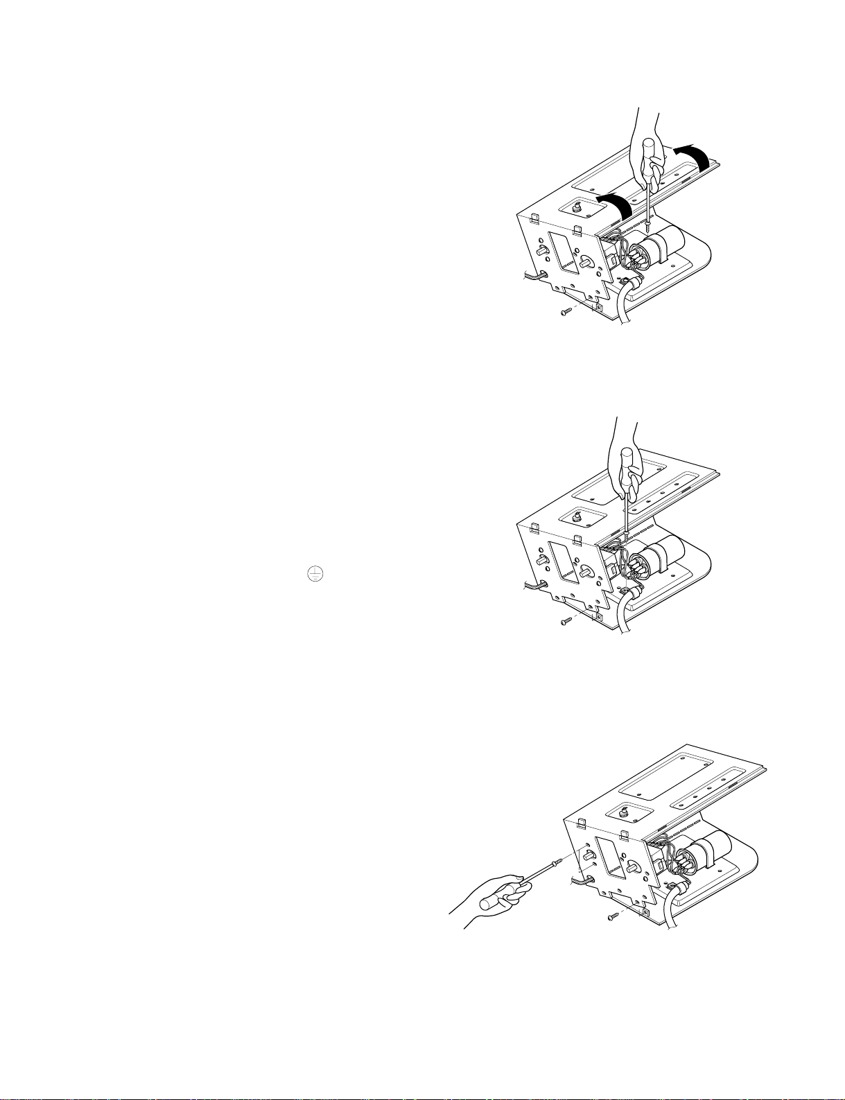
2.3.3 CAPACITOR
1. Remove the control box. (Refer to section 2.1.3)
2. Remove the screw and knobs which fasten the
display panel.
3. Disconnect the 2 leads from the rocker switch and
remove the panel.
4. Remove a screw and unfold the control box.
(See Fig. 11)
5. Remove the screw and the clamp which fastens
the capacitor. (See Fig. 11)
6. Disconnect all the leads of capacitor terminals.
7. Re-install the components by referring to the
removal procedure, above.
2.3.4 POWER CORD
1. Remove the control box. (Refer to section 2.1.3)
2. Unfold the control box. (Refer to section 2.3.3)
3. Disconnect the grounding screw from the control
box.
4. Disconnect 2 receptacles.
5. Remove a screw which fastens the clip cord.
6. Pull the power cord. (See Fig. 12)
7. Re-install the component by referring to the
removal procedure, above.
(Use only one ground-marked hole for ground
connection.)
8. If the supply cord of this appliance is damaged, it
must be replaced by the special cord.
(The special cord means the cord which has the
same specification marked on the supply cord
fitted to the unit.)
2.3.5 THERMOSTAT
1. Remove the control box. (Refer to section 2.1.3)
2. Unfold the control box. (Refer to section 2.3.3)
3. Remove the 2 screws which fasten the thermostat.
4. Disconnect all the leads of thermostat terminals.
5. Remove the thermostat. (See Fig. 13)
6. Re-install the components by referring to the
removal procedure, above.
Figure 12
Figure 11
Figure 13
Page 14

2.3.6 ROTARY SWITCH
1. Remove the control box. (Refer to section 2.1.3)
2. Unfold the control box. (Refer to section 2.3.3)
3. Remove 2 screws which fasten the rotary switch.
4. Disconnect all the leads of the rotary switch
terminals.
5. Remove the rotary switch. (See Fig. 14)
6. Re-install the components by referring to the
above removal procedure, above.
2.3.7 SYNCHRONOUS MOTOR
1. Remove the control box. (Refer to section 2.1.3)
2. Unfold the control box. (Refer to section 2.3.3)
3. Remove the crankshaft.
4. Disconnect all the leads of the synchronous
motor.
5. Remove the 2 screws which fasten the
synchronous motor. (See Fig. 15)
6. Re-install the components by referring to the
removal procedure, above.
—14—
Figure 15
Figure 14
Page 15

—15—
2.4 REFRIGERATION CYCLE
2.4.1 CONDENSER
1. Remove the cabinet. (Refer to section 2.1.2)
2. Remove the brace and the shroud cover.
(Refer to section 2.2.1)
3. Remove 6 screws which fasten the condenser.
4. After discharging the refrigerant completely,
unbraze the interconnecting tube at the condenser
connections.
5. Remove the condenser.
6. Re-install the components by referring to notes.
(See Fig. 16)
2.4.2 EVAPORATOR
1. Remove the cabinet. (Refer to section 2.1.2)
2. Remove the top cover and the brace.
(Refer to section 2.2.1)
3. Discharge the refrigerant completely.
4. Remove the 3 screws which fasten the evaporator
at the left side and the top side.
5. Move the evaporator sideward carefully and then
unbraze the interconnecting tube at the evaporator
connectors.
6. Remove the evaporator.
7. Re-install the components by referring to notes.
(See Fig. 17)
2.4.3 CAPILLARY TUBE
1. Remove the cabinet. (Refer to section 2.1.2)
2. Remove the brace. (Refer to section 2.2.1)
3. After discharging the refrigerant completely,
unbraze the interconnecting tube at the capillary
tube.
4. Remove the capillary tube.
5. Re-install the components by referring to notes.
Figure 16
Figure 17
Discharge the refrigerant system using Freon
TM
Recovery System.
If there is no valve to attach the recovery system,
install one (such as a WATCO A-1) before
venting the Freon
TM
. Leave the valve in place
after servicing the system.
CAUTION
Page 16

—16—
— Replacement of the refrigeration cycle.
1. When replacing the refrigeration cycle, be sure to
discharge the refrigerant system using a Freon
TM
recovery System.
If there is no valve to attach the recovery system,
install one (such as a WATCO A-1) before venting
the FreonTM. Leave the valve in place after
servicing the system.
2. After discharging the unit completely, remove the
desired component, and unbrace the pinch-off
tubes.
3. Solder service valves into the pinch-off tube ports,
leaving the valves open.
4. Solder the pinch-off tubes with Service valves.
5. Evacuate as follows.
1) Connect the vacuum pump, as illustrated Fig.
18A.
2) Start the vacuum pump, slowly open manifold
valves A and B with two full turns
counterclockwise and leave the valves closed.
The vacuum pump is now pulling through valves
A and B up to valve C by means of the manifold
and entire system.
3) Operate the vacuum pump for 20 to 30 minutes,
until 600 microns of vacuum is obtained. Close
valves A and B, and observe vacuum gauge for
a few minutes. A rise in pressure would
indicate a possible leak or moisture remaining in
the system. With valves A and B closed, stop
the vacuum pump.
4) Remove the hose from the vacuum pump and
place it on the charging cylinder. See Fig. 19B.
Open valve C.
Discharge the line at the manifold connection.
5) The system is now ready for final charging.
6. Recharge as follows :
1) Refrigeration cycle systems are charged from the
High-side. If the total charge cannot be put
in the High-side, the balance will be put in the
suction line through the access valve which you
installed as the system was opened.
2)
Connect the charging cylinder as shown in Fig. 18B.
With valve C open, discharge the hose at the
manifold connection.
3) Open valve A and allow the proper charge to
enter the system. Valve B is still closed.
4) If more charge is required, the high-side will not
take it. Close valve A.
5) With the unit running, open valve B and add the
balance of the charge.
a. Do not add the liquid refrigerant to the Low-
side.
b. Watch the Low-side gauge; allow pressure to
rise to 30 lbs.
c. Turn off valve B and allow pressure to drop.
d. Repeat steps B and C until the balance of the
charge is in the system.
6) When satisfied the unit is operating correctly,
use the pinch-off tool with the unit still running
and clamp on to the pinch-off tube. Using a tube
cutter, cut the pinch-off tube about 2 inches from
the pinch-off tool. Use sil-fos solder and solder
pinch-off tube closed. Turn off the unit, allow it to
set for a while, and then test the leakage of the
pinch-off connection.
NOTES
If high vacuum equipment is used, just crack
valves A and B for a few minutes, then open
slowly with the two full turns counterclockwise.
This will keep oil from foaming and being
drawn into the vacuum pump.
CAUTION
Page 17

—17—
Equipment needed: Vacuum pump, Charging cylinder, Manifold gauge, Brazing equipment. Pinch-off tool
capable of making a vapor-proof seal, Leak detector, Tubing cutter, Hand Tools to remove components, Service
valve.
A
COMPOUND GAUGE
EVAPORATOR
(LOW PRESSURE SIDE)
COMPRESSOR
CAPILLARY TUBE
CONDENSER
(HIGH PRESSURE SIDE)
SEE INSETS
BELOW
MANIFOLD
GAUGE
B
Figure 18A-Pulling Vacuum
Figure 18B-Charging
A
B
EXTERNAL
VACUUM PUMP
LOW
B
HI
A
CHARGING
CYLINDER
C
Page 18

—18—
3. TROUBLESHOOTING GUIDE
3.1 OUTSIDE DIMENSIONS
675 (770)
660
428
CAPILLARY TUBE
COMPRESSOR
BLOWER
EVAPORATOR COIL
CONDENSER COIL
FAN
MOTOR
: REFRIGERANT FLOW
3.2 PIPING SYSTEM
Following is a brief description of the important components and their functions in the refrigeration system.
Refer to Fig. 19 to follow the refrigeration cycle and the flow of the refrigerant in the cooling cycle.
MOTOR
COMPRESSOR
OIL
(LIQUID REFRIGERANT)
CAPILLARY TUBE
OUTSIDE COOLING
AIR FOR REFRIGERANT
PASS THROUGH
SUCTION LIME
COOL LOW PRESSURE VAPOR
COOLED
AIR
COMPLETE LIQUID
BOIL OFF POINT
LIQUID
PRESSURE
DROP
ROOM AIR HEAT LOAD
VAPOR INLET
HOT
DISCHARGED
AIR
LIQUID OUTLET
HIGH PRESSURE VAPOR
LIQUID PEFRIGERANT
LOW PRESSURE VAPOR
ROOM AIR CONDITIONER
EVAPORATOR COILS CONDENSER COILS
CYCLE OF REFRIGERATION
Figure 19
Page 19

—19—
3.3 TROUBLESHOOTING GUIDE
In general, possible trouble is classified in two causes.
The one is called Starting Failure which is caused from an electrical defect, and the other is Ineffective Air
Conditioning caused by a defect in the refrigeration circuit and improper application.
Unit runs but poor cooling
Ineffective Cooling
Check of outdoor coil
(heat exchanger) & the fan
operation.
Check gas leakage.
Repair gas leak.
Replacement of unit if the
unit is beyond repair.
Satisfactory operation with
temperature difference of
inlet & outlet air ; 7~10°C
Check heat load increase.
Unexpected residue
Overloaded Circuit
Check of inside gas
pressure.
Adjusting of refrigerant
charge
Malfunction of compressor
Replacement of
compressor
Check of cold air circulation
for smooth flow.
Dirty indoor coil
(Heat exchanger)
Malfunction of fan
Clogged of air filter
Obstruction at air outlet
Correct above trouble
Stop of auto air-swing
Check clogging in
refrigeration circuit.
Repair clogging in
refrigeration circuit.
Page 20

—20—
Fails to Start
Check of circuit breaker
and fuse.
Gas leakage of feeler bulb
of thermostat
Check of control switch.
Only fan fails to start.
Improper wiring.
Defect of fan motor
capacitor.
Irregular motor resistance
( ).
Irregular motor insulation
( ).
Replacement of fan motor
Regular but fails to start
Replacement of compressor
(locking of rotor, metal)
Improper thermostat setting
Loose terminal connection.
Improper wiring
Irregular motor resistance ( )
Irregular motor insulation ( )
Replacement of compressor
(Motor damaged)
Drop of power voltage.
Check capacitor.
Replacement.
Only compressor fails to
start.
Defect of compressor
capacitor.
Check of power source.
Check of control switch
setting.
Page 21

Electrical Parts Troubleshooting Guide : Micom Models
—21—
Possible Trouble 1 The unit does not operate.
• Check the Fuse.
• Check the wiring diagram.
Is the Trans output power
AC 220V?
Is the Trans output power
about AC 14V?
Is shorted the Trans. output?
Is output Voltage of IC01D
DC 12V?
Is output Voltage of IC02D
DC 5V?
Is the voltage No.20 of Micom
DC 5V?
Exchange Main PCB Ass'y.
Is the
connection between
Main and Display
all right?
Is the reset circuit all right?
(The No.16 of
Micom is 5V.)
• Check the Fuse.
• Check the wiring diagram.
• Check the Main
PCB pattern.
• Exchange the Trans.
• Exchange D02D~D05D.
• Exchange IC01D.
• Exchange IC02D.
• Exchange IC01A, C02A.
• Connect connector
exactly.
• Check the PCB
pattern.
NO
NO
NO
NO
NO
NO
NO
YES
YES
YES
YES
YES
YES
YES
NO
YES
Page 22

Is setting
Temp. set lower than Room
Temp.-0.5°C?
Is the voltage No.10
of IC01M 0V?
• Exchange IC01M.
• Select the setting Temp. to lower Number.
• Wait 3 Minutes.
Is the Unit for 3 minutes
delay?
• Exchange MAIN
PCB Ass'y.
Is the voltage N0.7 of
IC01M DC 5V?
• Check the RY-COMP.
• Check the wiring
Diagram.
NO
NO
NO
YES
YES
YES
YES
Is the wire connection of
RY-COMP all right?
• Check the RY-COMP.
• Connect LEAD Wire to
RY-COMP again.
NO
YES
NO
—22—
Possible Trouble 2 The compressor does not operate.
Possible Trouble 3 The compressor always operate.
Page 23

—23—
• Exchange IC01M.
• Exchange IC01M.
Is the voltage NO.2 or 3
of IC01M DC 5V?
Is the voltage NO.14 or 15
of IC01M 0V?
• Check the RY-Hi or
RY-Lo.
•
Check the wiring diagram.
NO
NO
YES
YES
• Exchange Micom.
• Exchange IC01M.
• Check the PCB pattern.
Is the voltage NO.6
of IC01M DC 5V?
Is the voltage NO.11
of IC01M 0V?
• Check the RY-SYNC.
• Check the connectionn
of CN-SYNC.
NO
NO
YES
YES
Possible Trouble 4 FAN does not operate.
Possible Trouble 5 Auto Swing does not operate.
Page 24

—24—
NO
NO
NO
NO
YES
YES
YES
Is the IC01G all right?
Is the connection of
CN-DISP2 all right?
• Exchange the display
PCB Ass'y.
• Exchange IC01G.
• Exchange Q12G,
Q13G, Q14G.
• Connect connector
to CN-DISP2 exactly.
Does the Q12G,
Q13G, Q14G operate normally
on main PCB Ass'y?
• Check the PCB pattern.
Is the voltage of Battery
about over 2.3V?
• Exchange Receiver Ass'y.
Is the connection of
CN-DISP2 all right?
Is the voltage No.10
of CN-DISP2 on Main PCB
Ass'y DC 5V?
• Exchange the battery.
• Check the PCB pattern.
• Connect connector to
CN-DISP2 exactly.
NO
NO
NO
YES
YES
YES
Possible Trouble 6 Remote controller does not operate.
Possible Trouble 7 It displays abnormally on display PCB Ass'y.
Page 25

—25—
NO
NO
YES
YES
Is the Knob of SW1
set to left position?
Is the voltage No.1 of
CN-DISP1 of Main PCB
Ass'y DC 5V?
• Reference to
OWNER'S MANUAL.
• Set the Knob of SW1
to left position.
• Check the SW1.
• Check the pattern of
Main & Display PCB.
Possible Trouble 8 The function of Auto Restart does not operate.
Page 26

—26——26—
COMPLAINT CAUSE REMEDY
Check voltage at outlet. Correct if none.
Check voltage to rotary switch. If none, check
power supply cord. Replace cord if circuit is open.
Check switch continuity. Refer to wiring diagram
for terminal identification. Replace switch if
defective.
Connect wire. Refer to wiring diagram for terminal
identification. Repair or replace loose terminal.
Test capacitor.
Replace if not within ±10% of manufacturer's
rating. Replace if shorted, open, or damaged.
Fan blade hitting shroud or blower wheel hitting
scroll. Realign assembly.
Units using slinger ring condenser fans must
have 1/4to 5/16inch clearance to the base. If it is
hitting the base, shim up the bottom of the fan
motor with mounting screw(s).
Check fan motor bearings; if motor shaft will not
rotate, replace the motor.
Check voltage. See limits on this page. If not within
limits, call an electrician.
Test capacitor.
Check bearings. Does the fan blade rotate freely?
If not, replace fan motor.
Pay attention to any change from high speed to
low speed. If the speed does not change, replace
the motor.
Check grommets; if worn or missing, replace them.
If cracked, out of balance, or partially missing,
replace it.
If cracked, out of balance, or partially missing,
replace it.
Tighten it.
If knocking sounds continue when running or
loose, replace the motor. If the motor hums or
noise appears to be internal while running,
replace motor.
No power
Power supply cord
Rotary switch
Wire disconnected or
connection loose
Capacitor (Discharge
capacitor before testing.)
Will not rotate
Revolves on overload.
Grommets
Fan
Blower
Loose set screw
Worn bearings
Fan motor will not run.
Fan motor runs
intermittently
Fan motor noise.
Page 27

—27—
COMPLAINT CAUSE REMEDY
Check voltage. See the limits on the preceding.
page. If not within limits, call an electrician.
Check the wire connections, if loose, repair or
replace the terminal. If wires are off, refer to wiring
diagram for identification, and replace. Check wire
locations. If not per wiring diagram, correct.
Check for continuity, refer to the wiring diagram
for terminal identification. Replace the switch if
circuit is open.
Check the position of knob If not at the coldest
setting, advance the knob to this setting and
restart unit.
Check continuity of the thermostat. Replace
thermostat if circuit is open.
Check the capacitor.
Replace if not within ±10% of manufacturers
rating. Replace if shorted, open, or damaged.
Check the compressor for open circuit or
ground. If open or grounded, replace the
compressor.
Check the compressor overload, if externally
mounted. Replace if open. (If the compressor
temperature is high, remove the overload, cool it,
and retest.)
Check the voltage. See the limits on the preceding page. If not within limits, call an electrician.
Check overload, if externally mounted.
Replace if open. (If the compressor temperature
is high, remove the overload, cool, and retest.)
If not running, determine the cause. Replace if
required.
Remove the cabinet. inspect the interior surface
of the condenser; if restricted, clean carefully
with a vacuum cleaner (do not damage fins) or
brush. Clean the interior base before
reassembling.
If condenser fins are closed over a large area
on the coil surface, head pressures will increase,
causing the compressor to cycle. Straighten the
fins or replace the coil.
Voltage
Wiring
Rotary
Thermostat
Capacitor (Discharge
capacitor before
servicing.)
Compressor
Overload
Voltage
Overload
Fan motor
Condenser air flow
restriction
Condenser fins
(damaged)
Compressor will not run,
but fan motor runs.
Compressor cycles
on overload.
Page 28

—28—
COMPLAINT CAUSE
REMEDY
Test capacitor.
Check the terminals. If loose, repair or replace.
Check the system for a restriction.
If restricted, clean of replace.
Close if open.
Determine if the unit is properly sized for the area to
be cooled.
Check the set screw or clamp. If loose or missing,
correct. If the blower or fan is hitting air guide,
rearrange the air handling parts.
Remove the cabinet and carefully rearrange tubing
not to contact cabinet, compressor, shroud, and
barrier.
Set the knob to HIGH COOL or LOW COOL while
rocker switch is ON.
Check terminals. If loose, repair or replace.
Check the synchronous motor for open circuit.
Capacitor
Wiring
Refrigerating system
Air filter
Exhaust damper door
Unit undersized
Blower or fan
Copper tubing
Rotary switch.
Wiring
Synchronous motor.
Compressor cycles
on overload.
Insufficient cooling or
heating
Excessive noise.
Auto air-swing fails.
Page 29

—29—
4. SCHEMATIC DIAGRAM
4.1 CIRCUIT DIAGRAM
• MODEL : LWN1860BCG(BCL, BCP, BAG)/LWN2260BCG(BCL)/LWM1860BCG(BCL)/LWM1820BCG(BCL)
LWM1821BCG(BCL)/LWN2120BCG(BCL)/LWM1830BCG(BCL)/LWN2130BCG(BCL)
LWN2131BAG/LWM2130AAG/BAG
• MODEL : LWN2123BCG • MODEL : LWN2120BHG/BHP
LWN2123BHG
WIRING DIACRAM
ROCKER SWITCH
WH
WH
SYNC. M.
POWER INPUT
WH(BL)BK(BR)
(Ribbed)
(Plain)
COMP.
LAMP
SYNC. M.
MOTOR
WH(BL)
POWER INPUT
(Plain)
GN/YL
BK(BR)
(Ribbed)
3854AR2206Y
BL
BL
RD
BK
R
C
S
YL
YL
RD
BK
BL
RD
ROTARY SWITCH
BK
BL
L7
1
8
6
4
5
3
2
H
M
OR(BR)
OR(BR)
BL
THERMOSTAT
CAPACITOR
YL WH
BK
WH(BR)BK(BR
)
ROCKER SWITCH
BK
RD
BK
BL
T/B2
F
C
H
23
1
WIRING DIAGRAM
T/B1
3854A90019A
WIRING DIAGRAM
BK(BR
)
WH
WH
WH
1
23
WH(BR) BK(BR)
78
5
6
3
4
1
2
BL
BL
BL
BL
BK
BK
BK
BK
REVERSING COIL
BK(RD)BK(RD
)
BK
BK
BK
BR
T/B2
T/B1
T/B3
T/B4
L2
L3 L1
SUMP
HEATER
THERMOSTAT
BK
RD
RD
RD RD
RD RD
BL
BL
BL
BL
BL
BK
BK
BK
BK
BL
DEICER
PWB ASSY
BR
LAMP
RD
RD
CAPACITOR
COMP
YL
OR
(BR)
OR(BR
)
MOTOR
SYNC.M.
YL
YL
YL
YL
R
P.T.C
S
C
ROCKER
SWITCH
F
C
C
H
HL
ROTARY SWITCH
(Plain) (Ribbed)
WH(BL
)
THERMISTOR
GN/YL
POWER INPUT
Page 30

—30—
• MODEL : LWM1860QCG(QCL)/LWN1860QCG(QCL)/LWN2260QCG(QCL)/LWM1820QCG(QCL)
LWM1821QCG(QCL)/LWN2120QCG(QCL)/LWM1830QCG(QCL)/LWN2130QCG(QCL)
.
WIRING DIAGRAM 3854AR2206Z
CN-TRANS 1
CN-DISP 1
CN-
SYNC
CN-DISP 2
RY-H
RY-L
BR
BR
CN-TRANS 2
FUSE 250V T2A
• MODEL : LWM1860QAG • MODEL : LWN2120QHG
WIRING DIAGRAM 3854A20003J
WIRING DIAGRAM 3854AR2330W
MOTOR
BL
BK
RD
BK
RD
BL BL
OR(BR)
BK
RD
OR(BR)
YL
F
C
H
CAPACITOR
R
C
COMP.
TRANSFORMER
S
BL
THERMISTOR
BK
OR(BR)
BK(BR)
POWER INPUT
(Plain)
CN-TH
RY-HI
CN-DISP
DISPLAY
P.W.B ASSY
RY-COMP
ZNR
MAIN P.W.B ASSY
RY-4WAY
CN-4WAY
BK(RD)BK(RD)
BK
T/B 1 T/B 2
BK
SUMP
HEATER
BK BK
RD RD
RD RD
REVERSING COIL
43
RY-LO
GN/YL(GN)
WH(BL)
(Ribbed)
YL
BR
BR
SYNC.
MOTOR
CN-
SYNC
RY-SYNC
GN/YL
(GN)
FUSE
250V/T2A
(115V/T2A)
OLP
Page 31

4.2 ELECTROINC CONTROL DEVICE
• MODEL: Micom Models
—31—
Page 32

4.3 COMPONENTS LOCATION (OF MAIN P.C.B ASM)
• MODEL: LWM1860QCG/QCL/QAG, LWN1860QCG/QCL, LWN2260QCG/QCL
LWM1820QCG/QCL, LWM1821QCG/QCL, LWN2120QCG/QCL
LWM1830QCG/QCL, LWN2130QCG/QCL
• MODEL: LWN2120BHG/BHP/QHG, LWN2123BHG
—32—
Page 33

—33—
4.4 COMPONENTS LOCATION (FOR DISPLAY P.C.B ASM)
• MODEL: LWM1860QCG/QCL/QAG, LWM1860QCG/QCL, LWN2260QCG/QCL
LWM1820QCG/QCL, LWM1821QCG/QCL, LWN2120QCG/QCL
LWM1830QCG/QCL, LWN2130QCG/QCL
• MODEL: LWN2120BHG/BHP/QHG, LWN2123BHG
JW11
1
1
10
11 1
6871A20118
JW09
JW10
Page 34

—34—
5. EXPLODED VIEW
• COOLING MODEL
152302
135313
135303
147581-1
147581-2
135312
249950
554031
148000
352390
349600
346811
130410
354210
349001
147582
359012
349480
W48602
W48602
559010
149980
554160
550140
552102
352111
W52106-2
W52106-1
35211A352113
130910
269310 W0CZZ
266003
135500
135510
137215
267110
266002
146812
264110
149410
W0CZZ
146812
135500
135510
263230
261704
268712
237200
238310
268714
264110
249950
Page 35

—35—
• HEATING MODEL
130910
135313
152302
149410
268712
552111
W52106-1
W52106-2
552116
135500
237200
264110
269310
264110
349480
149980
559011
W48602
148000
352390
W48602
359012
349001
349600
130410
346811
554030
135312
266003
268714
135500
237200
238310
263230
W0CZZ
147581-2
147581-1
567502
550140
561410
352111
554160
267110
354210
Page 36

—36—
6. REPLACEMENT PARTS LIST
130410 BASE ASSEMBLY, SINGLE 3041A30001B 3041A30002F 3041A30002F 3041A30002B 3041A30002F 3041A30001K R
130910 CABINET ASSEMBLY 3061AR6056B 3091AR6057B 3091AR6057B 3091AR6057B 3091AR6057B 3091AR6056B R
135303 GRILLE, INLET
3530AR1604A(5236AR1329A) 3530AR1604A(5236AR1329A) - 3530AR1604A(5236AR1329A)
3530AR1604A 3530AR1604D R
135312
GRILLE ASSEMBLY, FRONT(SINGLE)
3531A20005A(3531AR2632D) 3531A20005A(3531AR2632D)
3531A20005K
3531A20005A(3531AR2632D)
3531A20005L 3531A20005V R
135313 GRILLE INLET - - 3531A20005A - - 135500 COVER, CONTROL BOX 3550AR7245A 3550AR7245A - 3550AR7245A - - R
135510 COVER ASSEMBLY, CONTROL - - 3551A30015A - - 3551A30015A R
137215 PANEL ASSEMBLY, CONTROL 3721A20002A 3721A20002A 3721A20002A 3721A20002B 3721A20002A 3721A20035G R
146812 MOTOR ASSEMBLY, SYNC 2H01102A 2H01102A 2H01102A 2H01102A 2H01102A 2H01102A R
147581-1 LOUVER, HORIZONTAL
4758A7264A(-) 4758A7264A(-) 4758A7264A 4758A7264A(-) 4758A7264A(-)
4758AR7264F R
147581-2 LOUVER, HORIZONTAL
4758AR7278A(-) 4758AR7278A(-) 4758AR7278A 4758AR7278A(-) 4758AR7278A(-)
4758AR7278F R
147582 LOUVER, VERTICAL 4758AR6157A 4758AR6157A 4758AR6157A 4758AR6157A 4758AR6157A 4758AR6157A R
148000 BRACE 4800AR7271A 4800AR7272A 4800AR7272A 4800AR7271A 4800AR7272A 4800AR7271A R
149410 KNOB ASSEMBLY
4941A30001A (4941A30001B)
- 4941A30001A
4941A30001A (4941A30001B)
4941A30001A 4941A30001K R
149980 SHROUD 4998AR1597A 4998AR1597A 4998AR1597A 4998AR1597A 4998AR1597A 4998AR1597A R
152302 FILTER ASSEMBLY, A/C
5231AR6159A(5230AR1327A) 5231AR6159A(5230AR1327A)
5231AR6159A
5231AR6159A(5230AR1327A) 5231AR6159A(5230AR1327A)
5231AR6159D R
249950 CONTROL BOX ASSEMBLY, SINGLE 4995A20005D 4995A20005V/Y 4995A20057Q 4995A20005P 4995A20057Q 4995A20088G R
264110 POWER CORD ASSEMBLY 3H01307C 3H03555B 3H01307D 2H00677Q 3H01307D 3H01307C R
266002 SWITCH, ROCKER 2H01316C 2H01316C 2H01316C 2H01316C 2H01316C - R
266003 SWITCH, ROTARY 2H00598E 2H00598E 2H00598E 2H00598E 2H00598E 2H00598E R
269310 THERMOSTAT ASSEMBLY 2H01109L 2H01109M 2H01109M 2H01109L 2H01109M 2H01109M R
346811 MOTOR ASSEMBLY, SINGLE 4681AR6033A 4681AR6033H 4681AR6033H 4681AR6033B 4681AR6033H 4681AR6033F R
349001 DAMPER, VENTILATION 4900AR7256A 4900AR7256A 4900AR7256A 4900AR7256A 4900AR7256A 4900AR7265A R
349480 ORIFICE 4948AR7241A 4948AR7241A 4948AR7241A 4948AR7241A 4948AR7241A 4948AR7241A R
349600 MOTOR MOUNT 4960AR1596A 4960AR1596A 4960AR1596A 4960AR1596A 4960AR1596A 4960AR1596A R
352111 TUBE ASSEMBLY, CONNECTION 5211AR7059C 5211AR7059A 5211AR7059W 5211AR7059E 5211AR7059A 5211AR7059C R
352113 TUBE ASSEMBLY, DISCHARGE 5211A30003A 5211A30066B 5211A30066B 5211A30066A 5211A30066B 5211A30131A R
35211A TUBE ASSEMBLY, SUCTION 5211A30002A 5211A30154A 5211A30154A 5211A30065A 5211A30154A 5211A30130A R
352390 AIR GUIDE ASSEMBLY 5239A20001A 5239A20001A 5239A20001A 5239A20001D 5239A20001A 5239A20001A R
354210 EVAPORATOR ASSEMBLY 5421A20009A 5421A20009A 5421A20009A 5421A20017B 5421A20009A 5421A20017A R
359012 FAN ASSEMBLY, BLOWER 5834AR1599A 5834AR1599A 5834AR1599A 5834AR1599A 5834AR1599A 5834AR1599B R
550140 ISOLATOR, COMP - - 4022U-L005A - 4022U-L005A 4H01765A R
552101 TUBE CAPILLARY 5425AR3147A 3H03750L - 3H03750S - 5425AR3147X R
552102 TUBE, CAPILLARY BEND - - 5211A20020C - 5211A20020C - R
554031 CONDENSER ASSEMBLY, BENT 5403A20004B 5403A20004F 5403A20004F 5403A20004F 5403A20004K 5403A20004M R
554160 COMPRESSOR 5416AR1411D 5416AR1581C 5416AR1581C 5417AR2256E 5416AR1581C 1H00404D R
559010 FAN ASSEMBLY, AXIAL 5900AR1598A 5900AR1330A 5900AR1330A 5900AR1330A 5900AR1330A 5900AR1330A R
W0CZZ CAPACITOR 6120AR2194F 6120AR2194F 6120AR2194F 6120AR2194D 6120AR2194F 6120AR2194F R
W48602 CLAMP SPRING 3H02932C 3H02932C 3H02932C 3H02932C 3H02932C 3H02932C
W52106-1 TUBE, EVAPORATOR 5210A30009B 5210A30009G 5210A30009G 5210A30009D 5210A30009G 5210A30144A R
W52106-2 TUBE, EVAPORATOR 5210A30009A 5210A30009H 5210A30009H 5210A30009C 5210A30009H 5210A30144B R
PART NO.
DESCRIPTION
REMARK
LOCATION
NO
.
LWN1860
BCG(BCL)
LWM1860
BCG(BCL)
LWM1860
BCP
LWM1830
BCG(BCL)
LWM1860
BAG
LWN2123
BCG
Page 37

—37—
130410 BASE ASSEMBLY, SINGLE 3041A30002D 3041A30002B 3041A30001K 3041A30001H 3041A30001H R
130910 CABINET ASSEMBLY 3061AR6056B 3091AR6057B 3091AR6057B 3091AR6057B 3091AR6056B R
135303 GRILLE, INLET
3530AR1604A(5236AR1329A) 3530AR1604A(5236AR1329A) 3530AR1604A(5236AR1329A) 3530AR1604A(5236AR1329A)
3530AR1604A R
135312 GRILLE ASSEMBLY, FRONT
3531A20005A(3531AR2632D) 3531A20005A(3531AR2632D) 3531A20005A(3531AR2632D) 3531A20005A(3531AR2632D)
3531A20005L R
135500 COVER, CONTROL BOX 3550AR7245A 3550AR7245A 3550AR7245A 3550AR7245A 3550AR7245A R
135510 COVER ASSEMBLY, CONTROL - - - - 3551A30015A R
137215 PANEL ASSEMBLY, CONTROL 3721A20002A 3721A20002E 3721A20002B 3721A20002A R
146812 MOTOR ASSEMBLY, SYNC 2H01102A 2H01102A 2H01102A 2H01102A 2H01102A R
147581-1 LOUVER, HORIZONTAL 4758A7264A(-) 4758A7264A(-) 4758A7264A(-) 4758A7264A(-) 4758A7264A(-) R
147581-2 LOUVER, HORIZONTAL
4758AR7278A(-) 4758AR7278A(-) 4758AR7278A(-) 4758AR7278A(-) 4758AR7278A(-
)R
147582 LOUVER, VERTICAL 4758AR6157A 4758AR6157A 4758AR6157A 4758AR6157A 4758AR6157A R
148000 BRACE 4800AR7271A 4800AR7272A 4800AR7272A 4800AR7271A R
149410 KNOB ASSEMBLY
4941A30001A (4941A30001B) 4941A30001A (4941A30001B) 4941A30001A (4941A30001B) 4941A30001A (4941A30001B)
4941A30001A R
149980 SHROUD 4998AR1597A 4998AR1597A 4998AR1597A 4998AR1597A 4998AR1597A R
152302 FILTER ASSEMBLY, A/C
5231AR6159A(5230AR1327A) 5231AR6159A(5230AR1327A) 5231AR6159A(5230AR1327A) 5231AR6159A(5230AR1327A)
5231AR6159A
R
249950 CONTROL BOX ASSEMBLY, SINGLE
4995A20005B/C 4995A20005G 4995A20005S 4995A20005P 4995A20065J
R
264110 POWER CORD ASSEMBLY 3H01307C 3H01307C 3H01307C 2H00677Q 2H00677Q R
266002 SWITCH, ROCKER 2H01316C 2H01316C 2H01316C 2H01316C 2H01316C R
266003 SWITCH, ROTARY 2H00598E 2H00598E 2H00598E 2H00598E 2H00598E R
269310 THERMOSTAT ASSEMBLY 2H01109L 2H01109L 2H01109M 2H01109L 2H01109L R
346811 MOTOR ASSEMBLY, SINGLE 4681A20011A 4681AR6033C 4681AR6033F 4681AR6033G 4681AR6033M R
349001 DAMPER, VENTILATION 4900AR7256A 4900AR7256A 4900AR7256A 4900AR7256A 4900AR7256A R
349480 ORIFICE 4948AR7241A 4948AR7241A 4948AR7241A 4948AR7241A 4948AR7241A R
349600 MOTOR MOUNT 4960AR2895A 4960AR1596A 4960AR1596A 4960AR1596A 4960AR1596A R
352111 TUBE ASSEMBLY, CONNECTION 5211AR7059C 5211AR7059C 5211AR7059C 5211AR7059E 5211AR7059H R
352113 TUBE ASSEMBLY, DISCHARGE 5211A30003A 5211A30066A 5211A30131A 5211A30137A 5211A30293A R
35211A TUBE ASSEMBLY, SUCTION 5211A30064A 5211A30088B 5211A30130A 5211A30136A 5211A30292A R
352390 AIR GUIDE ASSEMBLY 5239A20001A 5239A20001A 5239A20001A 5239A20001A 5239A20001A R
354210 EVAPORATOR ASSEMBLY 5421A20017A 5421A20017A 5421A20017A 5421A20017B - R
359012 FAN ASSEMBLY, BLOWER 5834AR1599A 5834AR1599A 5834AR1599A 5834AR1599A 5834AR1599A R
550140 ISOLATOR, COMP - - - - - R
552101 TUBE CAPILLARY 5424AR3448L 5425AR3147T 5425AR3147X 5424AR3411P - R
552102 TUBE, CAPILLARY BEND - - - - 5211A30296A R
554031 CONDENSER ASSEMBLY, BENT 5403A20004B 5403A20004F 5403A20004B 5403A20013D 5403A20004T R
554160 COMPRESSOR 5416AR1411E 5417AR2256S 5416AR1422A 2H01564J 5416A20013E R
559010 FAN ASSEMBLY, AXIAL 5900AR1598A 5900AR1330A 5900AR1330A 5900AR1508A 5900AR1330A R
W0CZZ CAPACITOR 6120AR2194L 6120AR2194P 6120AR2194F 6120AR2194D 6120AR2194K R
W48602 CLAMP SPRING 3H02932C 3H02932C 3H02932C 3H02932C 3H02932C R
W52106-1 TUBE, EVAPORATOR 5210A30144B 5210A30009J 5210A30144B 5210A30009D 5210A30144B R
W52106-2 TUBE, EVAPORATOR 5210A30144A 5210A30009K 5210A30144A 5210A30009C 5210A30144A R
PART NO.
DESCRIPTION
REMARK
LOCATION
NO
.
LWN2260
BCG(BCL)
LWM1820/1
BCG(BCL)
LWN2120
BCG(BCL)
LWN2130
BCG(BCL)
LWN2131
BAG
Page 38

—38—
135312 FRONT GRILLE ASS'Y 3531A20005A (3531AR2632D) R
135313 INLET GRILLE 3530AR1604A (5236AR1329A) R
152302 AIR FILTER ASS'Y 5231AR6159A (5230AR1327A) R
147581-1 LOUVER HORIZONTAL 4758AR7264A(-) R
147581-2 LOUVER HORIZONTAL 4758AR7278A(-) R
554160 COMPRESSOR ASS'Y
5417AR2767F 5417AR2767G 5417AR6146E 5417AR2652B 2H01277W 5417AR2652A 2H02564H
R
130910 CABINET ASS'Y
3091AR6056B 3091AR6057B 3091AR6056B
R
147582 LOUVER VERTICAL 4758AR6157A R
349001 DAMPER 4900AR7265A R
349600 MOTOR MOUNT
4960AR1596A 4960AR2895A 4960AR4596A
R
346811 MOTOR ASS'Y
4681AR6033A 4681A20011A 4681AR6033H 4681AR6033C 4681AR6033F 4681AR6033B 4681AR6033G
R
359012 BLOWER 5834AR1599A R
352390 AIR GUIDE ASS'Y
5239A20001A 5239A20001D 5239A20001A
R
W48602 CLAMP 3H02932C R
349480 ORIFICE 4948AR7241A R
354210 EVAPORATOR ASS'Y
5421A20009A 5421A20017A 5421A20009A 5421A20017A 5421A20017B
R
149980 SHROUD 4998AR1597A R
559011 FAN
5900AR1598A 5900AR1330A 5900AR1508A 5900AR1330A
R
554031 CONDENSER ASS'Y
5403A20004B
5403A20004F 5403A20004B 5403A20004F 5403A20013D
R
148000 BRACE
4800AR7271A 4800AR7272A 4800AR7271A 4800AR7272A 4800AR7271A
R
249950 CONTROL BOX ASS'Y
4995A20045A 4995A20045B 4995A20045L 4995A20045C
R
268712 DISPLAY PWB ASM 6871A30005A R
268714 MAIN PWB ASM
6871A20037H 6871A20037K
R
W0CZZ CAPACITOR
6120AR2194F 6120AR2194D 6120AR2194F 6120AR2194P 6120AR2194F 6120AR2194D
R
264110 POWER CORD ASS'Y
3H01307C 3H03555B 3H01307C 2H00677Q
R
263230 THERMISTOR ASS'Y 6323AQ2333K R
237200 CONTROL PANEL 3720AR6163A R
238310 ESCUTCHEON 3841A10002A 3831A10002B R
146812 SYNCHRONOUS MOTOR 2H01102A R
135500 COVER CONTROL BOX 3550AR7245A R
261704 TRANSFORMER ASS'Y 6171AQ2258F R
35211A TUBE SUCTION ASS'Y
5211A30002A 5211A30064A 5211A30154A 5211A30088B 521130130A 5211A30065A 5211A30136A
R
352113 TUBE DISCHARGE ASS'Y
5211A30003A 5211A30066B 5211A30066A 5211A30131A 5211A30066A 5211A30137A
R
352111 TUBE CONNECTION ASS'Y
5211AR7059C 5211AR7059A 5211AR7059C 5211AR7059E
R
552101 TUBE CAPILLARY
5425AR3147A 5424AR3448L 3H03750L 5425AR3147T 5425AR3147X 3H03750S 5424AR3411P
R
267110
REMOTE CONTROLLER ASSEMBLY
6711AR2700B
6711A20018M
6711A20018M 6711AR2700L R
(6711AR2700B)
130410 BASE ASSEMBLY, SINGLE
3041A30001B 3041A30001D 3041A30002F 3041A30002B 3041A30001K 3041A30002B 3041A30001H
R
PART NO.
DESCRIPTION
REMARK
LOCATION
NO
.
LWN1860
QCG(QCL)
LWN2260
QCG(QCL)
LWM1860
QCG(QCL)
LWM1820/1
QCG(QCL)
LWN2120
QCG(QCL)
LWM1830
QCG(QCL)
LWN2130
QCG(QCL)
Page 39

—39—
LWM1860QAG LWM2130AAG LWM2130BAG
130410 BASE ASSEMBLY, SINGLE 3041A30002F 3041A30002B 3041A30002B R
130910 CABINET ASSEMBLY, SINGLE 3091AR6057B 3091AR6057B 3091AR6057B R
135312 GRILLE ASSEMBLY, FRONT(SINGLE) 3531A20005L 3531A20005L 3531A20005L R
135313 GRILLE, INLET 3530AR1604A 3530AR1604A 3530AR1604A R
135500 COVER - 3550A30048C 3550A30048C R
135510 COVER ASSEMBLY, CONTROL(SINGLE) 3551A30015A 3551A30015A 3551A30015A R
137215 PANEL ASSEMBLY, CONTROL - 3721A20035Y 3721A20002A R
146812 MOTOR ASSEMBLY, SYNC. 2H01102A - 2H01102A R
147581-1 LOUVER, HORIZONTAL 4758AR7264A 4758AR7264A 4758AR7264A R
147581-2 LOUVER, HORIZONTAL 4758AR7278A 4758AR7278A 4758AR7278A R
147582 LOUVER, VERTICAL 4758AR6157A - 4758AR6157A R
148000 BRACE 4800AR7272A 4800AR7272A 4800AR7272A R
149410 KNOB ASSEMBLY 4940AR7022A 4941A30001A 4941A30001A R
149980 SHROUD 4998AR1597A 4998AR1597A 4998AR1597A R
152302 FILTER ASSEMBLY, A/C 5231AR6159A 5231AR6159A 5231AR6159A R
237200 PANEL, CONTROL 3720AR6163A - - R
238310 ESCUTCHEON 3831A10002H - - R
249950 CONTROL BOX ASSEMBLY, SINGLE 4995A20100A 4995A20088K 4995A20088M R
261704 TRANSFORMER, POWER 6170A20006A - - R
263230 THERMISTOR ASSEMBLY 6323A20003D - - R
264110 POWER CORD ASSEMBLY 3H01307C 2H00677Q 2H00677Q R
266002 SWITCH, ROCKER - - 2H01316C R
266003 SWITCH, ROTARY - 2H00598E 2H00598E R
267110 REMOTE CONTROLLER ASSEMBLY 6711A20034N - - R
268712 PWB(PCB) ASSEMBLY, DISPLAY 6871A20118C - - R
268714 PWB(PCB) ASSEMBLY, MAIN 6871A10013A - - R
269310 THERMOSTAT ASSEMBLY - 2H01109L 2H01109L R
346811 MOTOR ASSEMBLY, SINGLE 4681AR6033H 4681AR6033U 4681AR6033U R
349001 DAMPER, VENTILATION 4900AR7265A 4900AR7265A 4900AR7265A R
349480 ORIFICE 4948AR7241A 4948AR7241A 4948AR7241A R
349600 MOUNT, MOTOR 4960AR1596A 4960AR1596A 4960AR1596A R
352111 TUBE ASSEMBLY, CONNECTOR 5211AR7059A 5211AR7059C 5211AR7059C R
352113 TUBE ASSEMBLY, DISCHARGE SINGLE 5211A30066B 5211A30066L 5211A30066L R
W52106-1 TUBE, EVAPORATOR 5210A30009G 5210A30144J 5210A30144J R
W52106-2 TUBE, EVAPORATOR 5210A30009H 5210A30144K 5210A30144K R
35211A TUBE ASSEMBLY, SUCTION SINGLE 5211A30154A 5211A30292D 5211A30292D R
352390 AIR GUIDE ASSEMBLY 5239A20001A 5239A20001C 5239A20001J R
354210 EVAPORATOR ASSEMBLY, FIRST 5421A20009A 5421A20017G 5421A20017G R
359012 FAN ASSEMBLY, BLOWER 5834AR1599A 5834AR1599B 5834AR1599B R
550140 ISOLATOR, COMP - 5040A30017A 5040A30017A R
552102 TUBE, CAPILARY BEND 5211A20020C 5211A20020T 5211A20020T R
554030 CONDENSER ASSEMBLY, FIRST - 5403A20004Y 5403A20004Y R
554031 CONDENSER ASSEMBLY, BENT 5403A20004K - - R
554160 COMPRESSOR 5416AR1581C 5416A20013E 5416A20013E R
559010 FAN ASSEMBLY, AXIAL 5900AR1330A 5900AR1330A 5900AR1330A R
W0CZZ CAPACITOR, DRAWING 6120AR2194F 6120AR2194K - R
W48602 CLAMP, SPRING 3H02932C 3H02932C 3H02932C R
PART NO.
DESCRIPTION
REMARK
LOCATION
NO
.
Page 40

—40—
LWN2120BHG LWN2120BHP LWN2120QHG LWN2123BHG
130410 BASE ASSEMBLY,SINGLE 3041A30001K 3041A30001K 3041A30001K 3041A30001K R
130910 CABINET ASSEMBLY,SINGLE 3091AR6056B 3091AR6056B 3091AR6056B 3091AR6056B R
135312 GRILLE ASSEMBLY,FRONT(SINGLE) 3531A20005X 3531A20005U 3531A20005F 3531A20005V R
135313 GRILLE,INLET 3530AR1604A 3530A10005B 3530AR1604A 3530AR1604D R
135510 COVER ASSEMBLY,CONTROL(SINGLE) 3551A30015A 3551A30015A 3551A30015A 3551A30015A R
137215 PANEL ASSEMBLY,CONTROL 3721A20002D 3721A20035H - 3721A20035H R
146812 MOTOR ASSEMBLY,SYNC. 2H01102A 2H01102A 2H01102A 2H01102A R
147581-1 LOUVER,HORIZONTAL 4758AR7264A 4758AR7264F 4758AR7264A 4758AR7264F R
147581-2 LOUVER,HORIZONTAL 4758AR7278A 4758AR7278F 4758AR7278A 4758AR7278F R
147582 LOUVER,VERTICAL 4758AR6157A 4758AR6157A 4758AR6157A 4758AR6157A R
148000 BRACE 4800AR7271A 4800AR7271A 4800AR7271A 4800AR7271A R
149410 KNOB ASSEMBLY 4941A30001A 4941A30001L - 4941A30001K R
149980 SHROUD 4998AR1597A 4998AR1597A 4998AR1597A 4998AR1597A R
152302 FILTER ASSY,A/C 5231AR6159A 5231AR6159D 5231AR6159A 5231AR6159D R
237200 PANEL,CONTROL - - 3720AR6163A - R
238310 ESCUTCHEON - - 3831A20032C - R
249950 CONTROL BOX ASSEMBLY,SINGLE 4995A20032D 4995A20032R 4995A20101A 4995A20032Q R
261704 TRANSFORMER,POWER - - 6170A20006A - R
263230 THERMISTOR ASSEMBLY 3Q35015N 3Q35015N 6323A20003E 3Q35015N R
264110 POWER CORD ASSEMBLY 3H01307C 3H01307C 3H01307D 3H01307C R
266002 SWITCH,ROCKER 2H01316C 2H01316C - 2H01316C R
266003 SWITCH,ROTARY 2H00598F 2H00598F - 2H00598F R
267110 REMOTE CONTROLLER ASSEMBLY - - 6711A20018B - R
268712 PWB(PCB) ASSEMBLY,DISPLAY - - 6871A20195G - R
268714 PWB(PCB) ASSEMBLY,MAIN - - 6871A20188W - R
269310 THERMOSTAT ASSEMBLY 2H01127D 2H01127D - 2H01127D R
346811 MOTOR ASSEMBLY,SINGLE 4681AR6033F 4681AR6033F 4681AR6033F 4681AR6033F R
349001 DAMPER,VENTILATION 4900AR7265A 4900AR7265A 4900AR7265A 4900AR7265A R
349480 ORIFICE 4948AR7241B 4948AR7241B 4948AR7241B 4948AR7241B R
349600 MOUNT,MOTOR 4960AR1596A 4960AR1596A 4960AR1596A 4960AR1596A R
W52106-1 TUBE,EVAPORATOR 5210A30144E 5210A30144E 5210A30144E 5210A30144E R
W52106-2 TUBE,EVAPORATOR 5210A30144F 5210A30144F 5210A30144F 5210A30144F R
352390 AIR GUIDE ASSEMBLY 5239A20001B 5239A20001B 5239A20001B 5239A20001B R
354210 EVAPORATOR ASSEMBLY,FIRST 5421A20017E 5421A20017E 5421A20017E 5421A20017E R
359012 FAN ASSEMBLY,BLOWER 5834AR1599B 5834AR1599B 5834AR1599B 5834AR1599B R
550140 ISOLATOR,COMP 4H01765A 4H01765A 4H01765A 4H01765A R
552101 TUBE,CAPILLARY 3H03750H 3H03750H 3H03750H 3H03750H R
554031 CONDENSER ASSEMBLY,BENT 5403A20013H 5403A20013H 5403A20013H 5403A20013R R
554160 COMPRESSOR ASSEMBLY 1H00404D 1H00404D 1H00404D 1H00404D R
559010 FAN ASSEMBLY,AXIAL 5900AR1330A 5900AR1330A 5900AR1330A 5900AR1330A R
W0CZZ CAPACITOR,DRAWING 6120AR2194F 6120AR2194F 6120AR2194F 6120AR2194F R
W48602 CLAMP,SPRING 3H02932C 3H02932C 3H02932C 3H02932C R
552116 TUBE ASSY,REVERSING 5211A30180A 5211A30180A 5211A30180A 5211A30180A R
552202 VALVE,REVERSING 3A02027A 3A02027A 3A02027A 3A02027A R
553000 HEATER,SUMP 2A00093L 2A00093L 2A00093L 2A00093L R
561410 COIL ASSEMBLY,REVERSING VALVE 3A02028Z 3A02028Z 3A02028Z 3A02028Z R
PART NO.
DESCRIPTION
REMARK
LOCATION
NO
.
Page 41

—41—
MEMO
Page 42

—42—
MEMO
Page 43

P/No.: 3828A30001N
October, 2006
Printed in Korea
 Loading...