

LG LWC121CGMK0, LWC143CSMK0, LWC243NSAB1, LWC143CGMK0, LWC243NSMM1 Service Manual

LG
Room
Air Conditioner
SERVICE MANUAL
LG
MODELS: LWC121CGMK0
LWC143CGMK0
LWC143CSMK0
LWC243NSAB1
LWC243NSMM1
CAUTION
website http://www.lgservice.com
• BEFORE SERVICING THE UNIT, READ THE SAFETY
PRECAUTIONS IN THIS MANUAL.
• ONLY FOR AUTHORIZED SERVICE PERSONNEL.

2 Room Air Conditioner
Air Conditioner Service Manual
TABLE OF CONTENTS
Safety Precautions..........................................................................................................................................3
Dimensions .....................................................................................................................................................7
Outside Dimensions..............................................................................................................
.....................7
Product Specifications ...............................................................................................................................
.11
Installation...............................................................................................................................
......................11
Select the Best Location ..........................................................................................................
...............11
Installation Check.....................................................................................................................................11
How to Secure the Drain Pipe..................................................................................................................11
How to Install(Installation kit not included models)...................................................................................12
How to Install(Installation kit included models).........................................................................................13
When Using Installation Kits ....................................................................................................................13
Suggested Tool Requirements .................................................................................................................14
Operation ......................................................................................................................................................17
Features...................................................................................................................................................17
Function of Controls.................................................................................................................................17
Disassembly..................................................................................................................................................20
Mechanical Parts......................................................................................................................................20
Air Handling Parts ....................................................................................................................................21
Electrical Parts.........................................................................................................................................22
Refrigerating Parts ...................................................................................................................................24
Schematic Diagram.......................................................................................................................................27
Electronic Control Device.........................................................................................................................27
Wiring Diagram.........................................................................................................................................28
Components Location ..............................................................................................................................29
Troubleshooting Guide.................................................................................................................................30
Piping System ..........................................................................................................................................30
Troubleshooting Guide .............................................................................................................................31
Room Air Conditioner Voltage Limits........................................................................................................33
Exploded View ..............................................................................................................................................35
Replacement Parts List ................................................................................................................................37
Service Manual 3
Safety Precautions
Safety Precautions
To prevent injury to the user or other people and property damage, the following instructions must
be followed.
■ Incorrect operation due to ignoring instruction will cause harm or damage. The seriousness is
classified by the following indications.
■ Meanings of symbols used in this manual are as shown below.
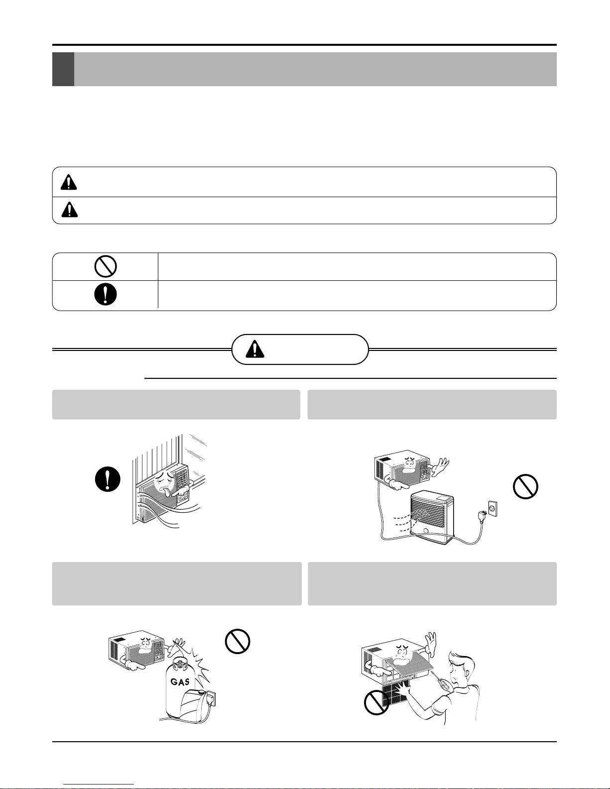
WARNING
CAUTION
This symbol indicates the possibility of death or serious injury.
This symbol indicates the possibility of injury or damage to property only.
WARNING
■ Installation
Always install the expansion panel(s).
• No installation may cause fire and electric shock acci-
dent.
Do not place the power cord near a heater.
• It may cause fire and electric shock.
Do not use the power cord near flammable gas
or combustibles such as gasoline, benzene,
thinner, etc.
• It may cause explosion or fire.
Do not disassemble or modify products.
• It may cause failure and electric shock.
Be sure not to do.
Be sure to follow the instruction.
Gasolin
4 Room Air Conditioner
Safety Precautions
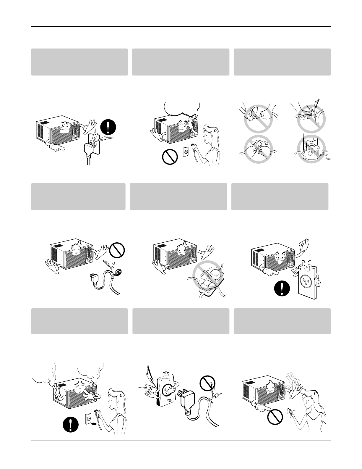
■ Operational
Plug in the power plug properly .
• Otherwise, it will cause electric
shock or fire due to heat generation
or electric shock.
Do not operate or stop the
unit by inserting or pulling out
the power plug.
• It will cause electric shock or fire
due to heat generation.
Do not damage or use an
unspecified power cord.
• It will cause electric shock or fire.
Do not modify power cord
length.
• It will cause electric shock or fire
due to heat generation.
Do not share the outlet with
other appliances.
• It will cause electric shock or fire
due to heat generation.
Always plug into a grounded
outlet.
• No grounding may cause electric
shock (See Installation Manual).
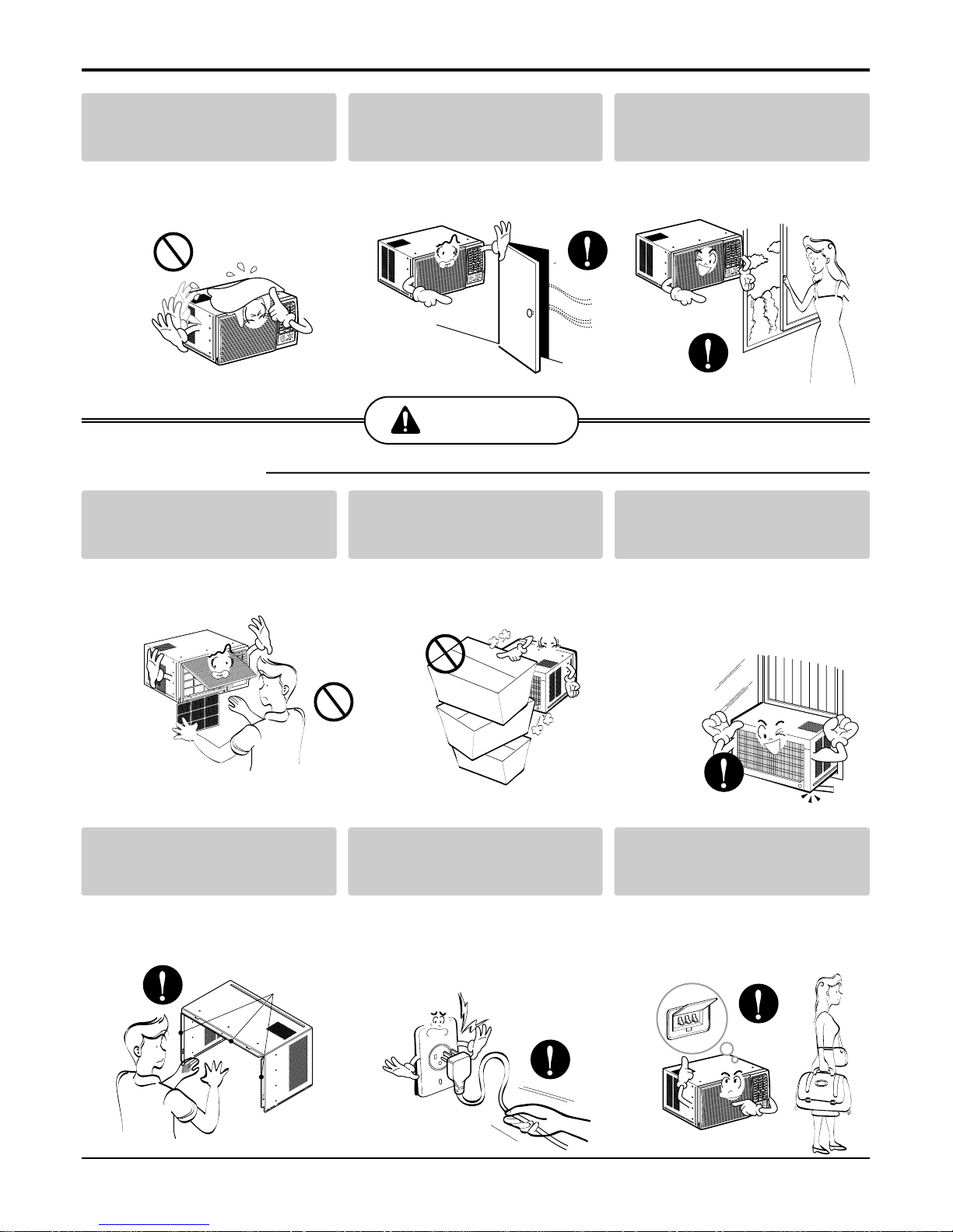
Unplug the unit if strange
sounds, odors, or smoke
come from it.
• Otherwise it may cause fire and
electric shock accident.
Do not use the socket if it is
loose or damaged.
• It may cause fire and electric
shock.
Do not operate with wet hands
or in damp environment.
• It will cause electric shock.
ON
Service Manual 5
Safety Precautions
CAUTION
■ Installation
Do not allow water to run into
electric parts.
• It will cause failure of machine or
electric shock.
Leave the door closed while
the air conditioner is running.
• It is not designed to cool the entire
house.
Ventilate before operating air
conditioner when gas goes
out.
• It may cause explosion, fire, and
burn.
Never touch the metal parts
of the unit when removing the
filter.
• They are sharp and may cause
injury.
Do not block the inlet or outlet.
• It may cause failure of appliance or
accident.
Ensure that the outer case is
not damaged by age or wear.
• If leaving appliance damaged,
there is concern of damage due to
the falling of product.
Be cautious not to touch the
sharp edges when installing.
• It may cause injury.
Hold the plug by the head
when taking it out.
• It may cause electric shock and
damage.
Turn off the main power
switch when not using it for a
long time.
• Prevent accidental startup and the
possibility of injury.
Sharp
edges
6 Room Air Conditioner
Safety Precautions
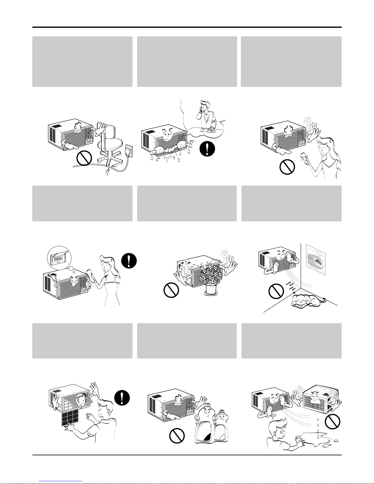
Do not place heavy object on
the power cord and take care
so that the cord should not be
pressed.
• There is danger of fire or electric
shock.
If water enters the product, turn
off the the power switch of the
main body of appliance. Contact
service center after taking the
power-plug out from the socket.
Do not clean the air
conditioner with water.
• Water may enter the unit and
degrade the insulation. It may
cause an electric shock.
Turn off the power and breaker firstly when cleansing the
unit.
• Since the fan rotates at high speed
during operation, it may cause
injury.
Do not put a pet or house
plant where it will be exposed
to direct air flow.
• This could injure the pet or plant.
Do not use this appliance for
special purposes such as
pets, foods, precision
machinery, or objects of art.
• It is an air conditioner, not a precision refrigeration system.
Always insert the filter
securely.
Clean it every two weeks.
• Operation without filters will cause
failure.
Use a soft cloth to clean. Do
not use wax, thinner, or a
strong detergent.
• The appearance of the air conditioner may deteriorate, change
color, or develop surface flaws.
Do not drink water drained
from air conditioner. / Do not
direct airflow at room
occupants only.
• It contains containments and will
make you sick. / This could damage your health.
Wax
Thinner
Service Manual 7
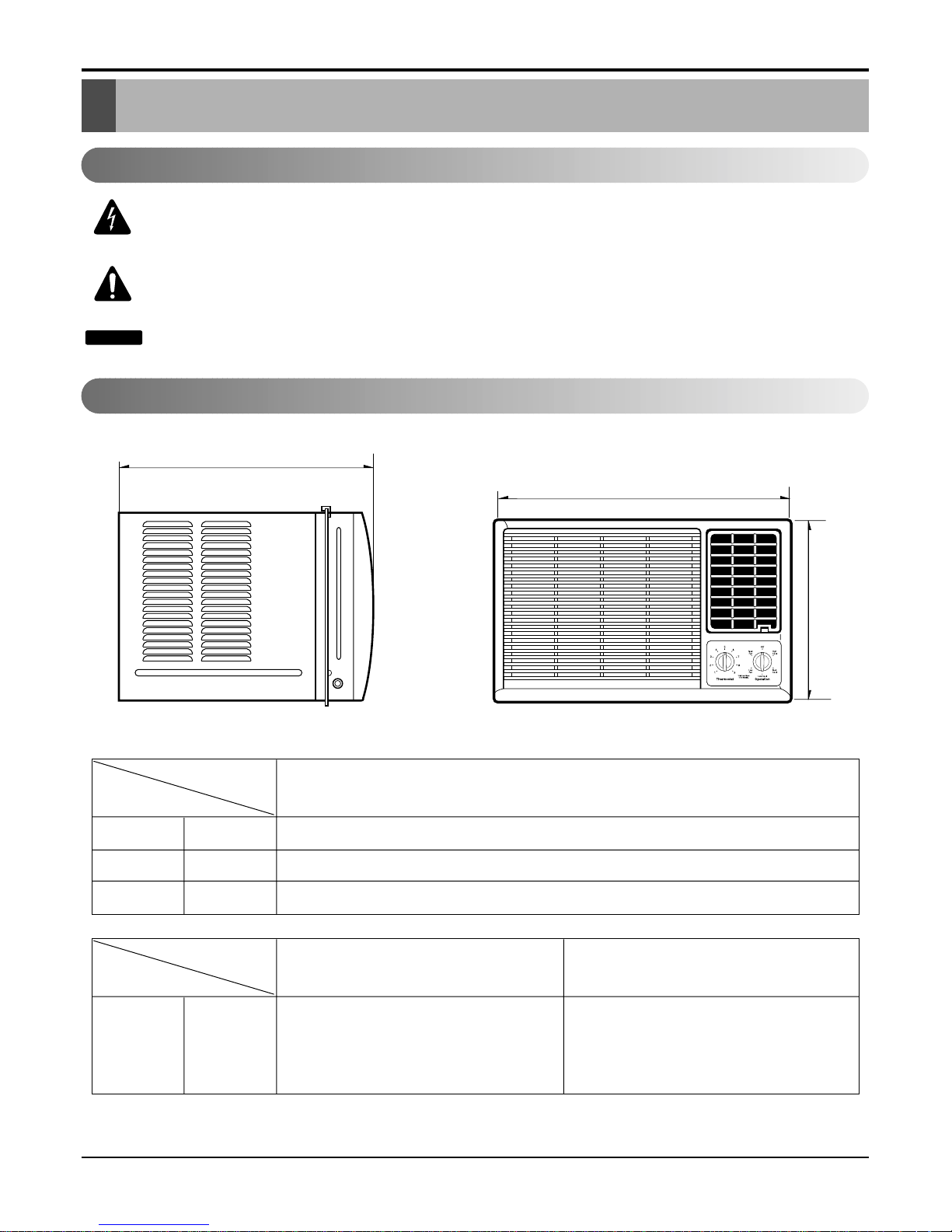
Dimensions
Dimensions
H
W
D
W mm(inch) 600(235/8)
H mm(inch) 380(1431/32)
D mm(inch) 567(22
5
/16)
Model
Dimension
12K , 14K MODELS
D mm(inch) 560(225/
16") 555(21
6
/
7")
Look
Dimension
G/P/E N
Outside Dimensions
This symbol alerts you to the risk of electric shock.
This symbol alerts you to hazards that could cause harm to the
air conditioner.
This symbol indicates special notes.
NOTICE
Symbols Used in this Manual
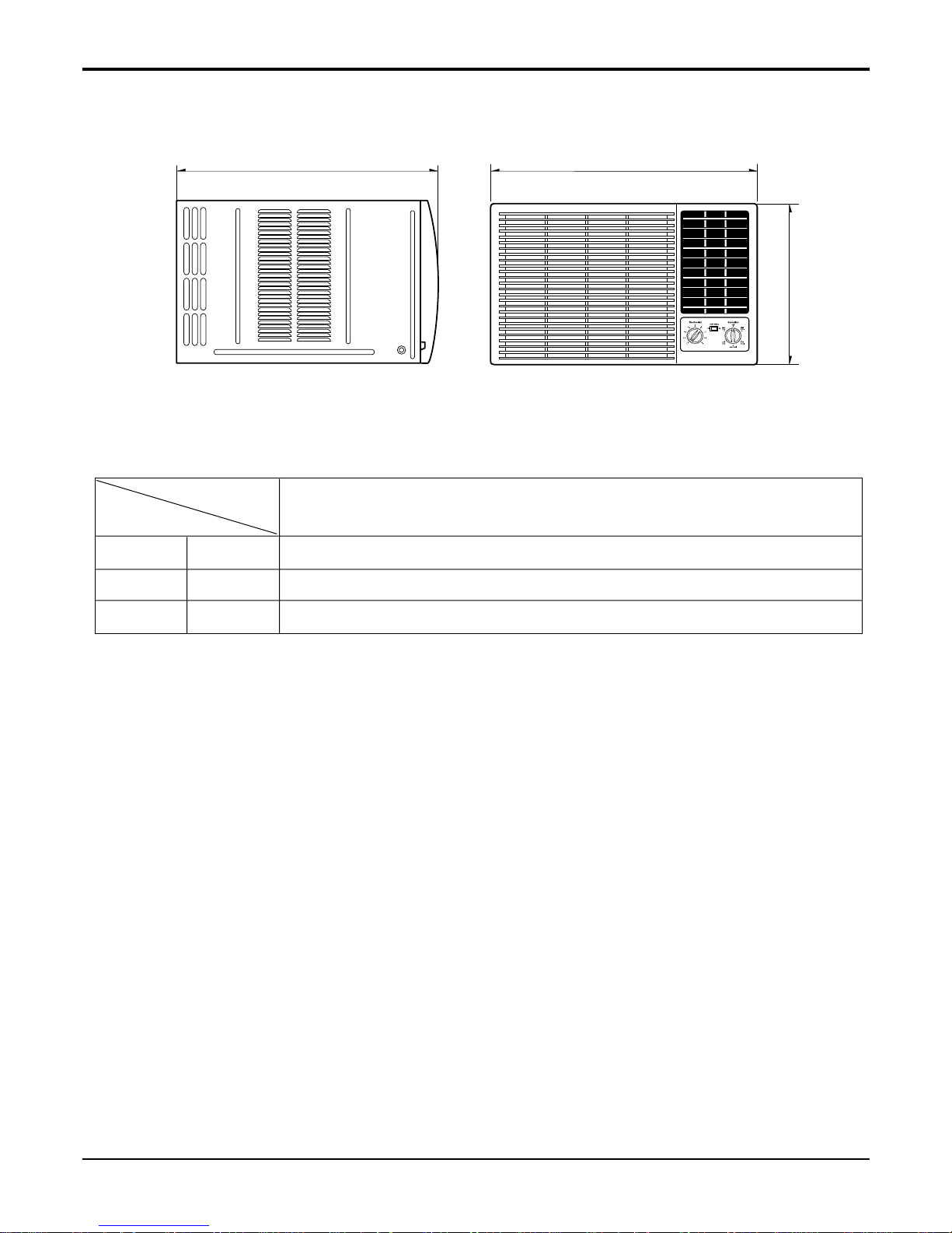
8 Room Air Conditioner
D
W
H
W mm(inch) 660(26")
H mm(inch) 428(1627/
32")
D mm(inch) 675(26
9
/18")
Model
Dimension
24K Btu
Dimensions
Service Manual 9
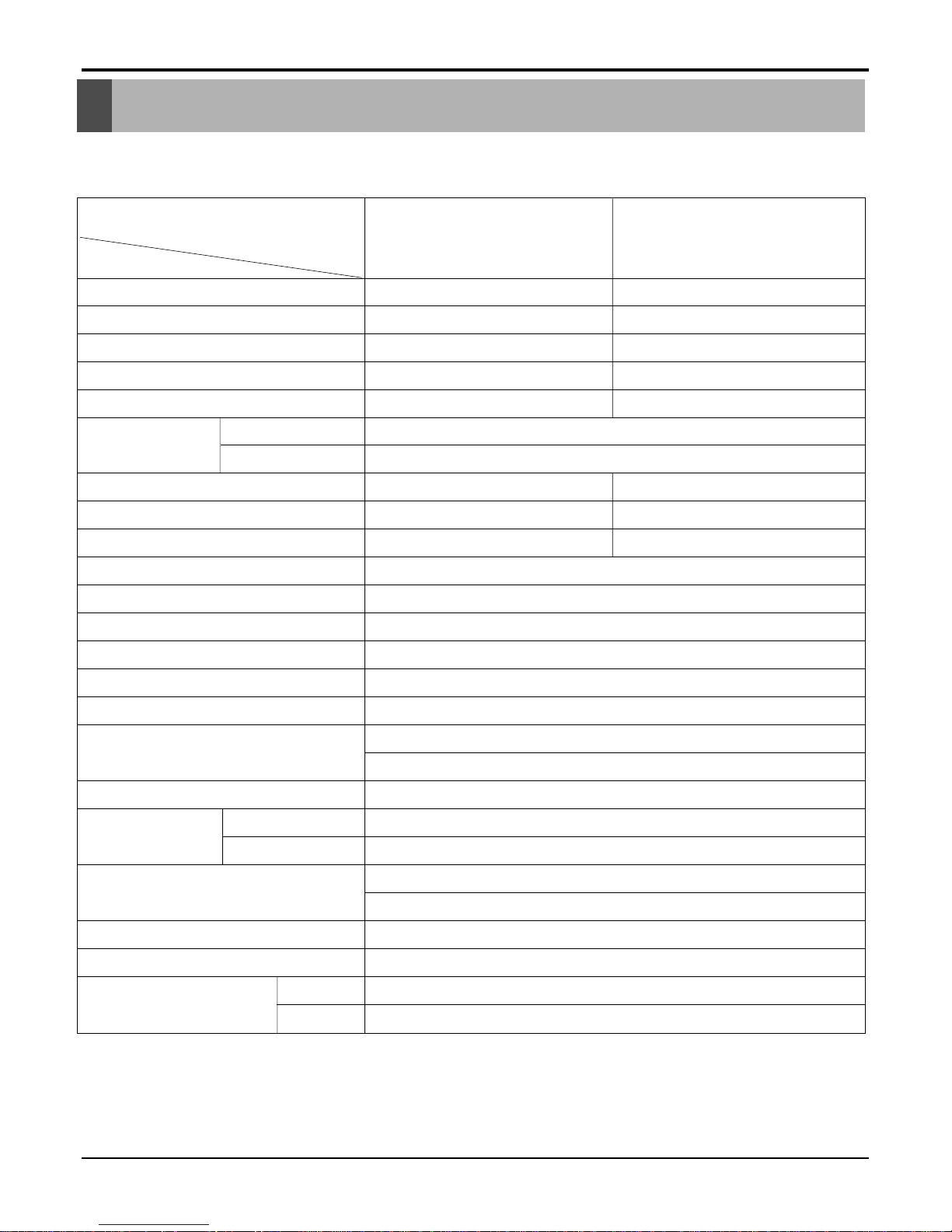
Product Specifications
* DB:Dry Bulb
**
WB:Wet Bulb
NOTE: Please refer to Label Quality on the produst since this specification may be changed for improving performance.
LWC121CGMK0
LWC143CGMK0
LWC143CSMK0
POWER SUPPLY
COOLING CAPACITY (Btu/h)
INPUT (W)
RUNNING CURRENT (A)
E.E.R (BTU/W.h)
OPERATING
INDOOR (°C)
CONDITION
OUTDOOR (°C)
REFRIGERANT (R-22) CHARGE
EVAPORATOR
CONDENSER
FAN, INDOOR
FAN, OUTDOOR
FAN SPEEDS, FAN/COOLING
FAN MOTOR
OPERATION CONTROL
ROOM TEMP. CONTROL
AIR DIRECTION CONTROL
CONSTRUCTION
PROTECTOR
COMPRESSOR
FAN MOTOR
POWER CORD
DRAIN SYSTEM
NET WEIGHT (lbs/kg)
OUTSIDE DIMENSION (inch)
(WxHxD) (mm)
1Ø,115V,60Hz 1Ø,220V,60Hz
12,000 14,000
1,220 1,400
11 6.2
9.8 10
26.7(DB),19.4(WB)
35(DB),23.9(WB)
355g(12.5oz) 670g(23.6oz)
2 ROW 16STACKS 2 ROW 13STACKS
2 ROW 18STACKS 2 ROW 14STACKS
TURBO
PROPELLER TYPE FAN WITH SLINGER-RING
3/3
6 POLES
REMOTE CONTROLLER
THERMISTOR
VERTICAL LOUVER(RIGHT&LEFT)
HORIZONTAL LOUVER (UP&DOWN)
SLIDE IN-OUT CHASSIS
OVERLOAD PROTECTOR
INTERNAL THERMAL PROTECTOR
(3 WIRE WITH GROUNDING)
ATTACHMENT PLUG (CORD-CONNECTED TYPE)
DRAIN PIPE OR SPLASHED BY FAN SLINGER
95/43
235/8x1431/32x225/16
600 x 380 x 567
MODELS
ITEMS
Specfications
10 Room Air Conditioner
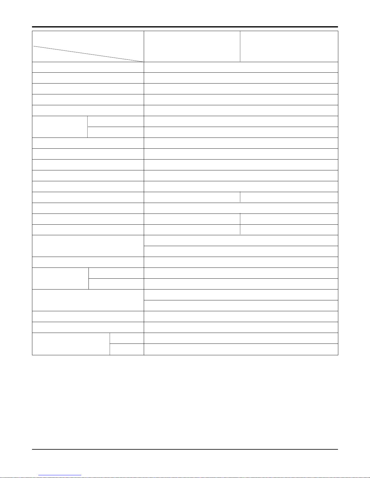
Specfications
* DB:Dry Bulb
**
WB:Wet Bulb
NOTE: Please refer to Label Quality on the produst since this specification may be changed for improving performance.
LWC243NAB1 LWC243NSMM1
POWER SUPPLY
COOLING CAPACITY (Btu/h)
INPUT (W)
RUNNING CURRENT (A)
E.E.R (BTU/W.h)
OPERATING
INDOOR (°C)
CONDITION
OUTDOOR (°C)
REFRIGERANT (R-22) CHARGE
EVAPORATOR
CONDENSER
FAN, INDOOR
FAN, OUTDOOR
FAN SPEEDS, FAN/COOLING
FAN MOTOR
OPERATION CONTROL
ROOM TEMP. CONTROL
AIR DIRECTION CONTROL
CONSTRUCTION
PROTECTOR
COMPRESSOR
FAN MOTOR
POWER CORD
DRAIN SYSTEM
NET WEIGHT (lbs/kg)
OUTSIDE DIMENSION (inch)
(W x H x D) (mm)
1Ø,220V,60Hz
24,000
2,820
12.9
8.5
26.7(DB),19.4(WB)
35(DB),23.9(WB)
985g(34.8oz)
3 ROW 15STACKS
2 ROW 19STACKS
TURBO
PROPELLER TYPE FAN WITH SLINGER-RING
2/3 3/3
6 POLES
ROTARY SWITCH REMOTE CONTROLLER
THERMISTOR THERMISTOR
VERTICAL LOUVER(RIGHT&LEFT)
HORIZONTAL LOUVER (UP&DOWN)
SLIDE IN-OUT CHASSIS
OVERLOAD PROTECTOR
INTERNAL THERMAL PROTECTOR
(3 WIRE WITH GROUNDING)
ATTACHMENT PLUG (CORD-CONNECTED TYPE)
DRAIN PIPE OR SPLASHED BY FAN SLINGER
146/66
265/8x1627/32x269/18
660 x 428 x 675
MODELS
ITEMS
Service Manual 11
Installation
Installation
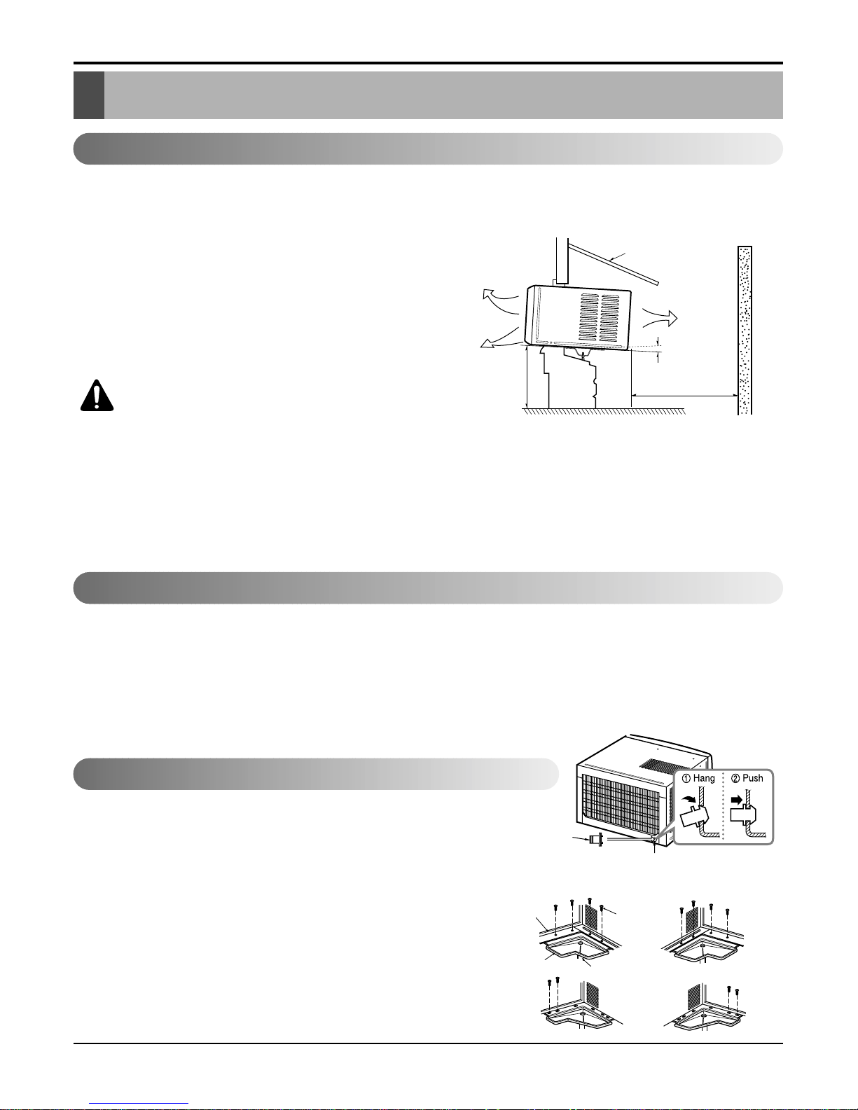
Select the Best Location
Installation Check
How to Secure the Drain Pipe(When using drain pipe)
1.To prevent vibration and noise, make sure the unit is
installed securely and firmly.
2.Install the unit where the sunlight does not shine directly
on the unit.
3.The outside of the cabinet must extend outward for at
least 12" and there should be no obstacles, such as a
fence or wall, within 20" from the back of the cabinet
because it will prevent heat radiation of the condenser.
Restriction of outside air will greatly reduce the cooling
efficiency of the air conditioner.
CAUTION: All side louvers of the cabinet
must remain exposed to the outside of
the structure.
4.Install the unit a little slanted so the back is slightly lower
than the front (about1/2"). This will help force condensed
water to the outside.
5.Install the unit from the bottom about 30"~60" above the
floor level.
The setting conditions must be checked prior to initial starting.
The following items are especially important check points when the installation is finished.
1. Grounding wire (Green or Green and Yellow) is provided in the power cord. The green wire must be grounded.
2. Connect to a single-outlet 15A circuit.
(or 20A circuit for Electric Heater Model)
3. To avoid vibration or noise, make sure the air conditioner is installed securely.
4 Avoid placing furniture or draperies in front of the air inlet and outlet.
In humid weather, excess water may cause the BASE PAN to overflow. To drain
the water, remove the DRAIN CAP and secure the DRAIN PIPE to the rear hole of
the BASE PAN. Press the drain pipe into the hole by pushing down and away from
the fins to avoid injury.
Optional
1. Install the drain pan over the corner of the cabinet where you removed the
plug with 4 (or 2) screws.
2. Connect the drain hose to the outlet located at the bottom of the drain pan.
You can purchase the drain hose or tubing locally to satisfy your particular
needs. (Drain hose is not supplied).
3. Select the most appropriate connection from among the following figures (by
considering the hole of the unit) to fit drain pan to your own unit.
AWNING
COOLED AIR
HEAT
RADIATION
30"~60"
ABOUT 1/2"
Over 20"
FENCE
Drain pipe
Drain cap
Fig. 4
Fig. 3
Fig. 2
DRAIN
PAN
DRAIN HOSE
Fig. 1
CABINET
SCREW
Figure 1
12 Room Air Conditioner
Installation
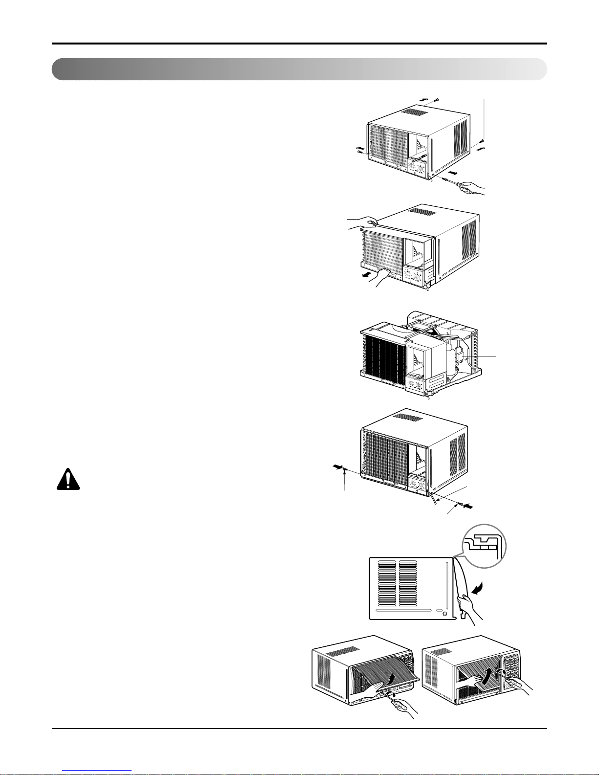
How to Install (Models without Installation kit)
1. Remove the screws which fasten the cabinet
at both sides and at the back.
2. Slide the unit from the cabinet by gripping
the base pan handle and pulling forward
while bracing the cabinet.
3. Remove EPS Material.
4. Slide the unit into the cabinet.
CAUTION: For security purpose, reinstall screw at cabinet's sides.
5. Attach the front grille to the cabinet by
inserting the tabs on the grille into the tabs
on the fornt of the cabinet. Push the grille in
until it snaps into place.
6. Lift the inlet grille and secure it with a screw
through the front grille.
Shipping screws
EPS Material
Power cord
Screw
Screw
• For MODELS : LWC121CGMK0 / LWC143CGMK0
 Loading...