

LG LW2414HR User Manual [en, es]

OWNER’S MANUAL
AIR CONDITIONER
Please read this manual carefully before operating
your air conditioner and retain it for future reference.
TYPE WINDOW
MODELS LW1814HR, LW2414HR
P/NO MFL68061603
www.lgappliances.com
Safety Precautions
Before Operation
Introduction
Electrical Safety
Installation
Operating Instructions
Maintenance and Service
7
16
20
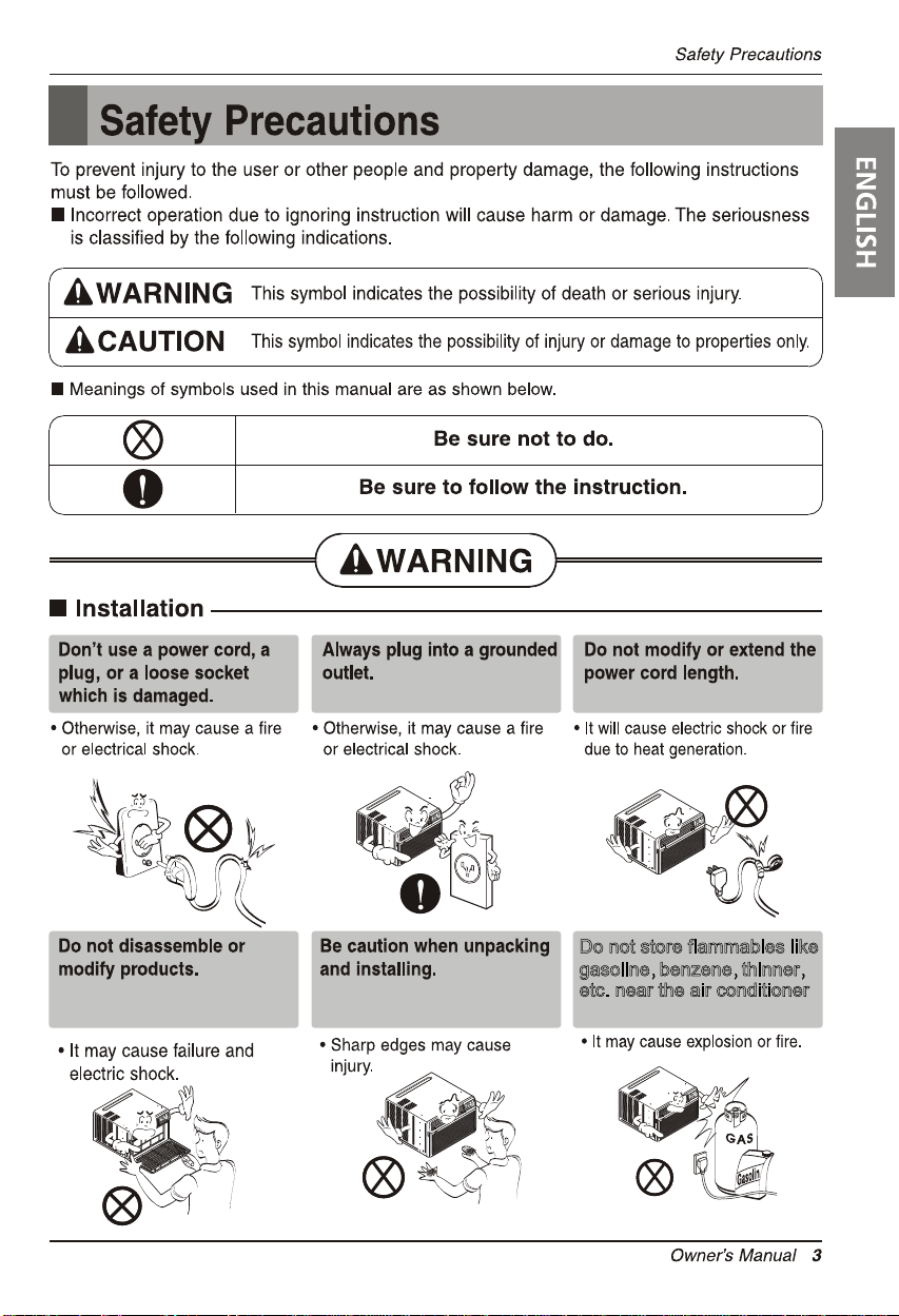
Do not store flammables like
gasoline benzene thinner
etc. near the air conditioner
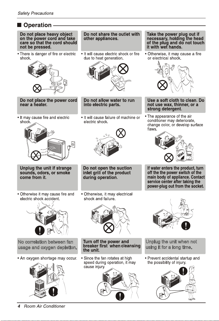
No correlation between fan
usage and oxygen depletion.
Unplug the unit when not
using it for a long time.
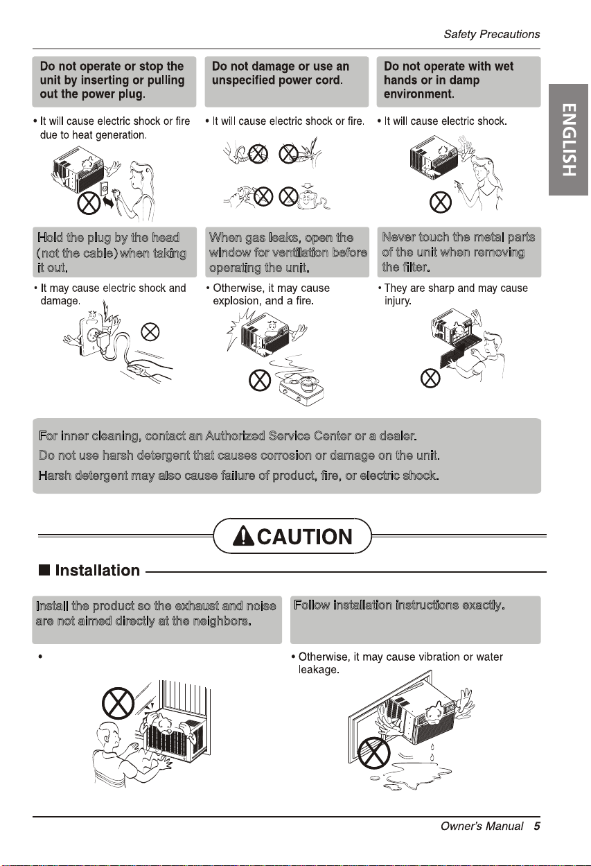
Hold the plug by the head
(not the cable)when taking
it out.
For inner cleaning, contact an Authorized Service Center or a dealer.
Do not use harsh detergent that causes corrosion or damage on the unit.
Harsh detergent may also cause failure of product, fire, or electric shock.
When gas leaks, open the
window for ventilation before
operating the unit.
Never touch the metal parts
of the unit when removing
the filter.
Install the product so the exhaust and noise
are not aimed directly at the neighbors.
Be considerate.
Follow installation instructions exactly.
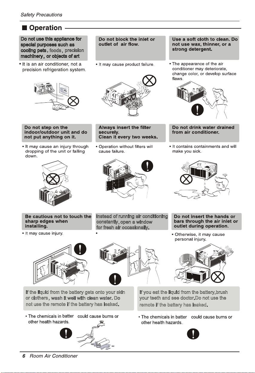
Do not use this appliance for
special purposes such as
,
cooling pets
foods,
precision
machinery,or objects of art
Instead of running air conditioning
constantly
for fresh air occasionally.
You will feel better.
If the liquid from the battery gets onto your skin
or clothers,
wash it well with clean water. Do
not use the remote if the battery has leaked.
y
,open a window
If you eat the liquid from the battery,brush
your teeth and see doctor.Do not use the
remote if the battery has leaked.
y
2. No correlation between fan usage and oxygen depletion.
3.
8 Room Air Conditioner
Introduction
This symbol alerts you to the risk of electric shock.
This symbol alerts you to hazards that could cause harm to
the air conditioner.
This symbol indicates special notes.
NOTICE
This appliance should be installed in accordance with the National Electric Code.
Introduction
Symbols Used in this Manual
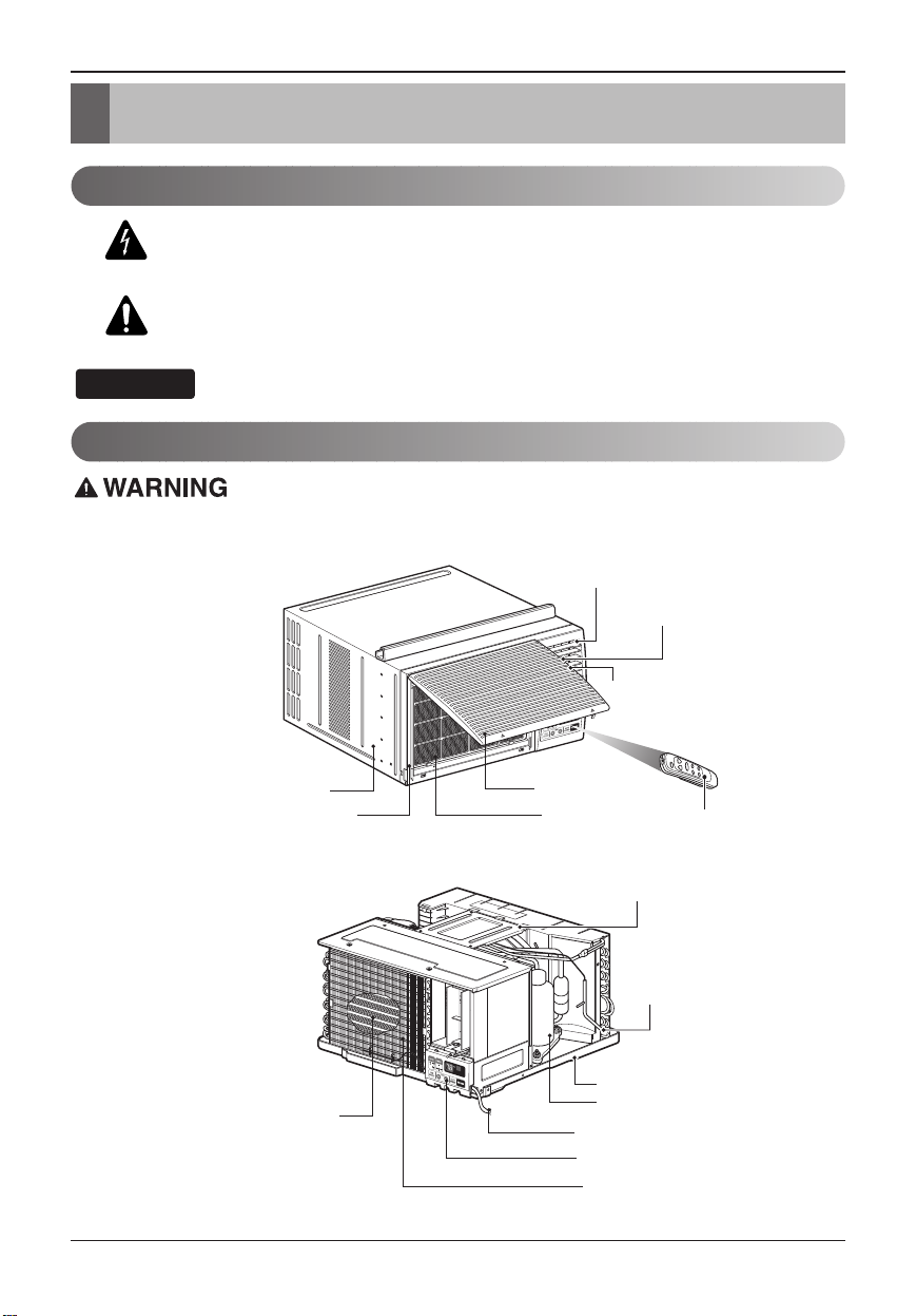
Features
Vertical Air Deflector
(Horizontal Louver)
Horizontal Air Deflector
(Vertical Louver)
Cabinet
Electric Heater
Air Discharge
Air Intake (Inlet Grille)
retliF riAellirG tnorF
Remote Controller
Brace
Condenser
Base Pan
Compressor
Power Cord
Control Board
Evaporator
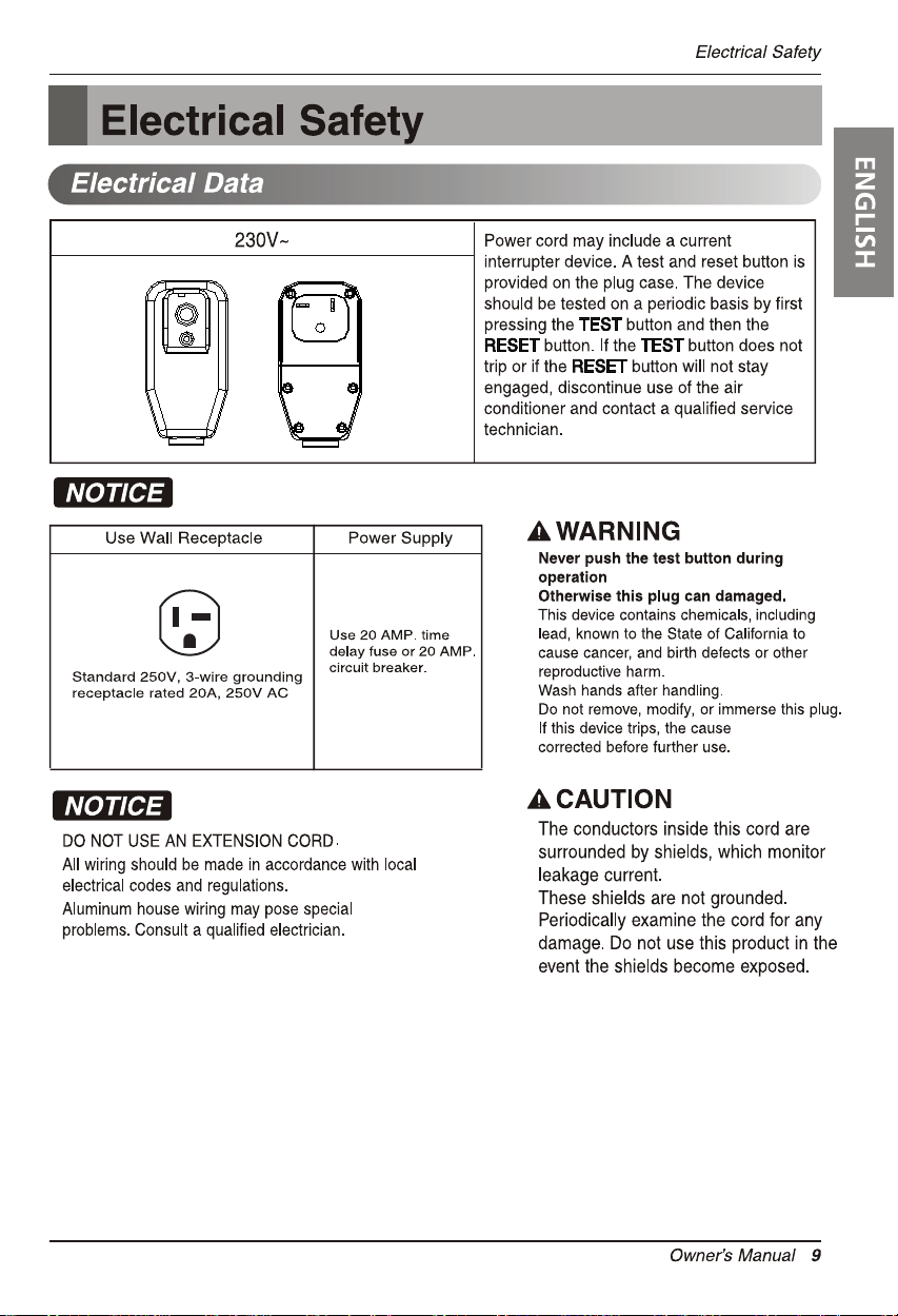
RESET
TEST
should be
Avoid shock hazard. This unit cannot
be user-serviced. Do NOT open the
tamper-resistant sealed portion.
All warranties and performance will
be voided. This unit is not intended
to be used as an ON/OFF switch.
Installation
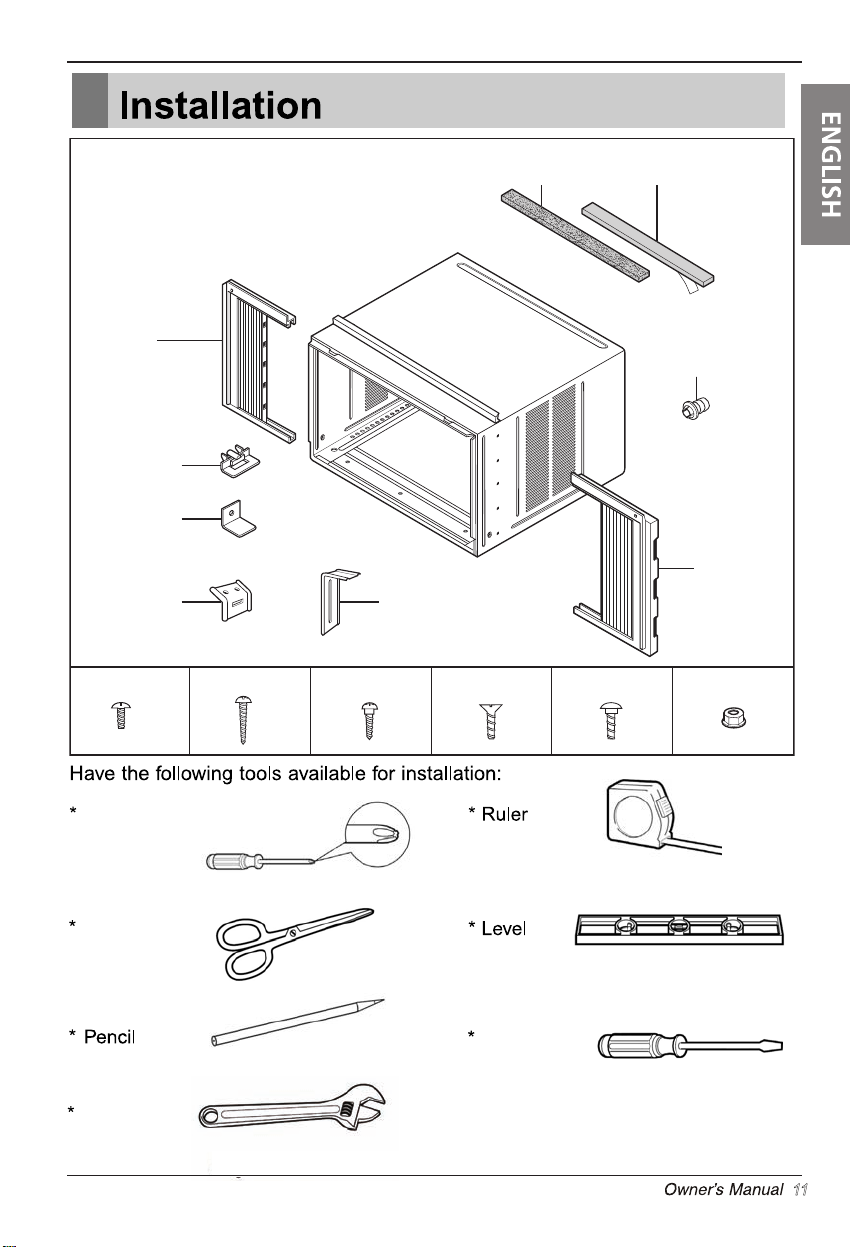
Left frame
curtain
Frame guide(2)
Window locking
bracket
bracket
Sill
Type A (11)
(2)
Type B (7)
Foam strip
(Plain-Back)
Support bracket(2)
Type C (5) Type D (2)
Foam-PE
(Adhesive-Backed)
Drain joint pipe
Right frame
curtain
Carriage Bolt (2) Lock Nut (4)
Phillips head
screwdriver
Scissors or
knife
Adjustable
Wrench
Flat - blade
screwdriver
11
Installation
NOTICE
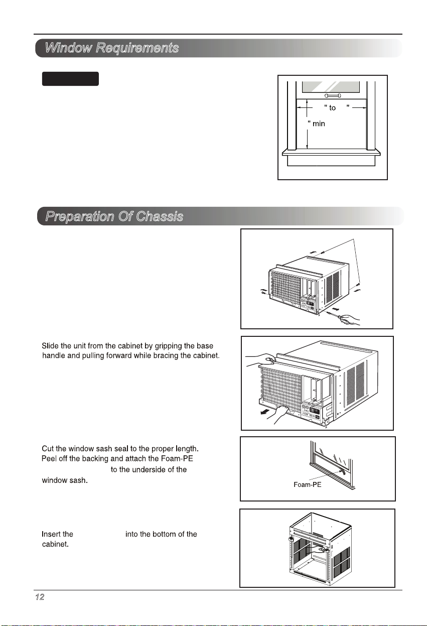
Window Requirements
All supporting parts should be secured to firm wood, masonry,
or metal.
1.This unit is designed for installation in standard double hung
windows with actual opening widths from 29" to 41".
The top and bottom window sashes must open sufficiently to
allow a clear vertical opening of 18" from the bottom of the
upper sash to the window stool.
2.The stool offset (height between the stool and sill) must be
less than 1 1/4".
Preparation Of Chassis
1.
Remove 4 screws which fasten the cabinet at both
sides and at the back.
(Keep the screws for Iater use.)
29 41
18
Shipping screws
2.
3.
( adhesive backed)
4.
12 Room Air Conditioner
pan
(Adhesive backed)
frame guides
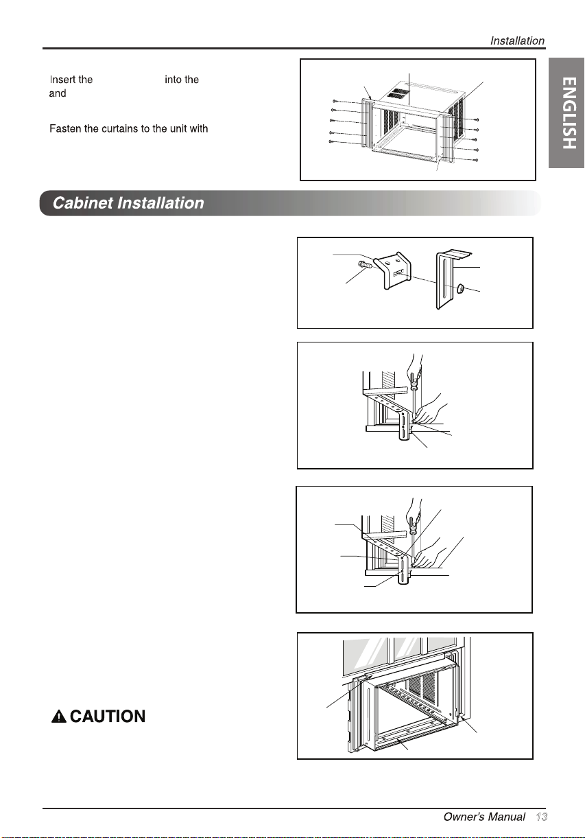
5.
6.
screws.
frame curtain
frame guides.
upper guide
Type
10
A
Left Guide panel
Screws
(Type A)
Upper guide
Frame guide
Right Guide Panel
1. Open the window.Mark a line on the center of
the window stool
.
Loosely attach the sill bracket to the support
bracket using the carriage bolt and the lock nut.
2. Attach the sill bracket to the window sill using
the screws (Type B).
Carefully place the cabinet on the window stool
and align the center mark on the bottom front
with the center hole marked window stool.
3. Using the screw (Type D) and the lock nut, attach
the support bracket to the cabinet track hole. Use
the first track hole after the sill bracket on the
outer edge of the window sill. Tighten the
carriage bolt and the lock nut. Be sure the
cabinet slants outward.
4. Pull the bottom window sash down behind the
t op retainer bar until they meet.
Sill
Bracket
Carriage
Bolt
Cabinet
Track hole
Support
Bracket
Carriage bolt
and lock nut
Support
Bracket
Lock nut
Screw (Type B)
Sill bracket
Machine screw (Type D)
and lock nut
Outer edge
of window
sill
Do not drill a hole in the bottom pan. The unit is
designed to operate with approximately 1/2" of
water in bottom pan.
Top
retainer
bar
Front angle
Window stool
13
Installation
NOTICE
1. Do not pull the window sash down so tightly
that the movement of frame curtain is
restricted. Attach the cabinet to the window
stool by driving the screws (Type B) through
the cabinet into window stool.
2.The cabinet should be installed with a very
slight tilt downward toward the outside.
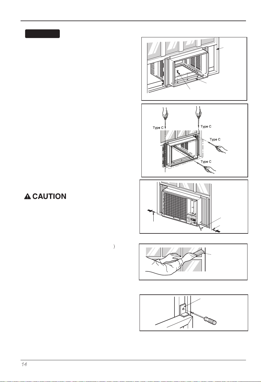
3.
Pull each frame curtain fully to each window sash
track, and pull the bottom window sash down behind
the t op retainer bar until it meets.
4.
Attach each frame curtain the window sash by
using screws (Type C).
5.
Slide the unit into the cabinet.
For security purpose, reinstall screws
(removed from cabinet)at cabinet's sides.
See page 13.
Screw
Sash track
Front Angle
Screw(Type B)
Power Cord
Screw (Type A)
Cut the foam-strip
6.
to the proper length and insert between the
upper window sash and the lower window sash.
7.
Attach the Window locking bracket with a screw
(Type C).
14 Room Air Conditioner
(
Not adhesive backed
Foam-Strip
(Not adhesive backed)
Window locking
bracket
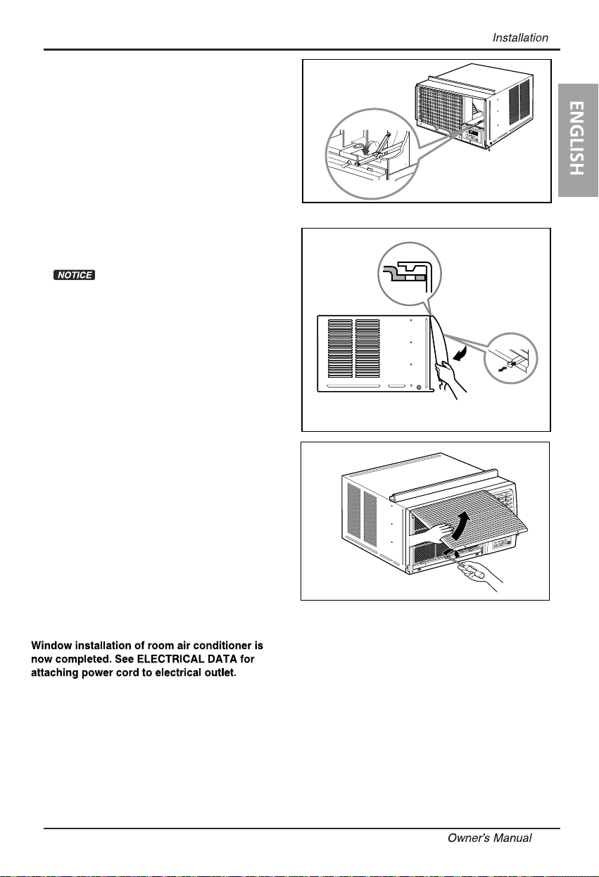
8.
Before installing the front grille, pull out
the vent control lever located above the
unit control knobs, as shown.
9.
Attach the front grille to the cabinet by inserting
the tabs the grille into the slots on the front the
cabinet. Push the grille in until it snaps into place.
Guide the lever carefully through the grille as
you push it in.
10.
Lift the inlet grille and secure it with a Type
A screw through the front grille.
15
 Loading...