


U
U
LW2100AP User’s Manual
Version 1.4
L
L
s
s
W
W
err’’
e
2
2
s
s
1
1
0
M
M
0
0
0
a
a
A
A
n
n
P
P
u
all
u
a
2002.05.14
Copyright© 2002 LG Electronics Inc., LTD.
Page 1 of 46

LW2100AP User’s Manual
Version 1.4
2002.05.14
Contents
Chapter 1 Overview of the system.......................................................................................... 4
1.1 Introduction......................................................................................................................... 4
1.1.1. Specification ............................................................................................................................... 5
1.1.2. Appearance.................................................................................................................................. 6
1.1.3. Components................................................................................................................................ 8
1.2. Hardware Installation............................................................................................... 9
1.3. Network Setting for PC..........................................................................................11
Chapter 2 WEB Server Manual........................................................................................ 14
2.1 Execution of WEB Server and AP connection to WEB
Server
............................................................................................................................................... 14
2.2. Menu description of WEB Server............................................................... 16
2.2.1. Basic configuration Menu......................................................................................................... 16
2.2.2. 802.11b Menu........................................................................................................................... 20
2.2.3. RADIUS Server Menu.............................................................................................................. 23
2.2.4. DHCP/NAT Server Menu ...................................................................................................... 25
2.2.5. SNMP Server Menu............................................................................................................... 27
2.2.6. DMZ Server Menu................................................................................................................. 29
2.2.7. MAC Filter Menu ..................................................................................................................... 30
2.2.8. IP Filter Menu........................................................................................................................... 32
2.2.9 Advanced Menu...................................................................................................................... 34
2.2.10. Save Menu.............................................................................................................................. 36
2.2.11. Reboot Menu........................................................................................................................... 37
2.2.12. Upgrade Menu ........................................................................................................................ 38
2.2.13. Default Value Menu ................................................................................................................ 39
Chapter 3 Console Window Manual.................................................................................. 40
3.1. Connecting Console Window......................................................................... 40
3.2. Setting Configuration Elements.................................................................. 43
Copyright© 2002 LG Electronics Inc., LTD.
Page 2 of 46

LW2100AP User’s Manual
Version 1.4
2002.05.14
All the contents described in the document may not be used without written permission of LG
Electronics Inc., Ltd.
This user manual may be changed without notification as function and specification of
LW2100AP have changed, and the changed contents can be free downloaded when you visit
our LG Electronics homepage
(http://www.lgnetwork.com/)
The intellectual rights of this user manual belong to LG Electronics Inc., Ltd.
Microsoft, Windows, Windows95, Windows98, Windows ME, Windows 2000 and Windows NT
are trademarks of Microsoft Corporation.
Other company names or products stated in this user manual may be trademarks of each
company or owner.
Copyright© 2002 LG Electronics Inc., LTD.
Page 3 of 46

LW2100AP User’s Manual
Version 1.4
2002.05.14
Chapter 1 Overview of the system
1.1 Introduction
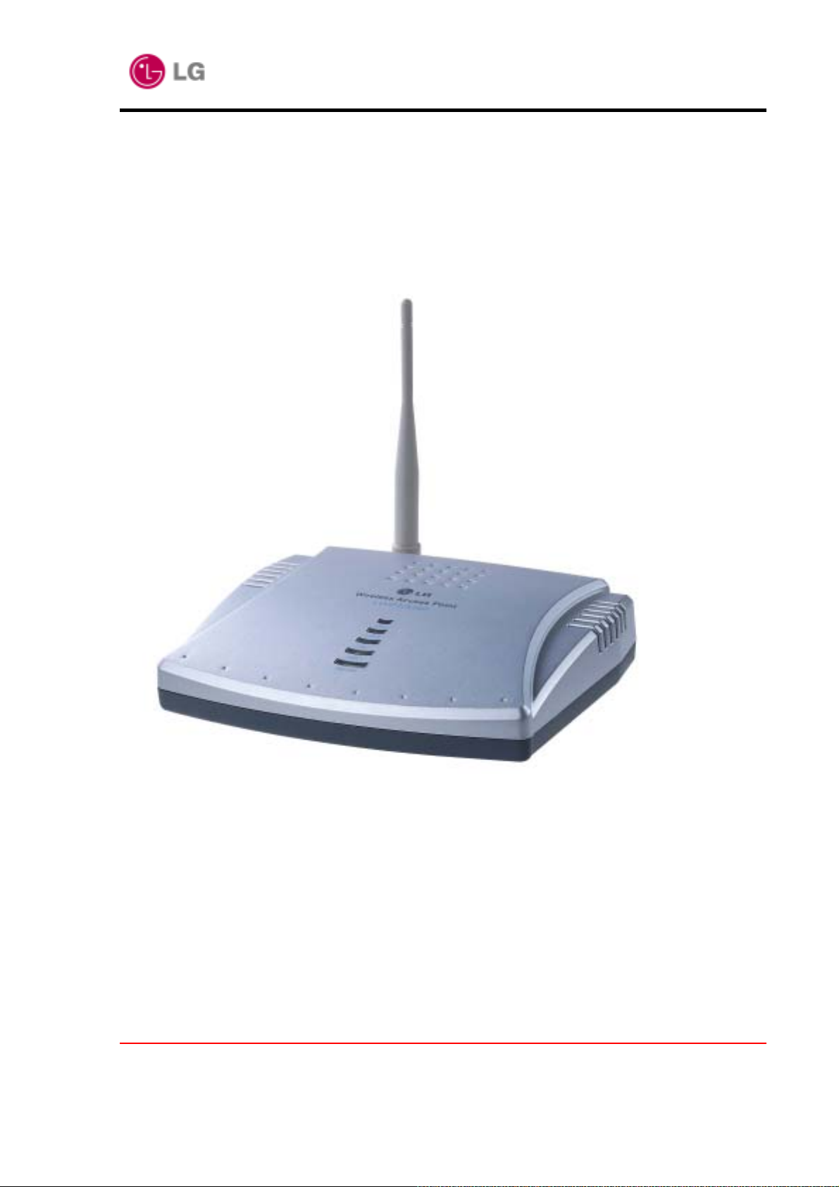
The LW2100AP delivers the freedom to configure the network without wire and functions as an
IEEE 802.3 Ethernet-based Residential Gateway. It provides 10/100 Dual Speed Ethernet port
for a DSL Modem, Cable Modem, or other Broadband access device and one 10M Ethernet port
for connection to a home or small office network.
LW2100AP can forward all packet between local and Internet such as ICMP, FTP, Real Audio,
Quake, H.225 packet. Also support virtual server(DMZ server) that forward incoming packet to
specified LAN host system.
LW2100AP supports DHCP server to setup network configuration for each local PC dynamically.
LW2100AP use graphical user interface(web-browser) to setup, check system status, change
password, and upgrade system image.
The LW2100AP has one local 10Mbps Ethernet port and one 10/100Mbps Dual Speed Ethernet
global port. The local port can be connected directly to a single computer or it can be
connected to an Ethernet hub or switch to provide Internet Sharing and Firewall protection to a
local area network. The global port can be connected to any Cable, DSL, or Broadband mode m
with an Ethernet port.
Unlike proxy server or NAT software that requires the software server to remain visible on the
Internet, no local computers are directly and externally visible when using the LW2100AP.
Integrated DHCP services allow up to 63 users to get their IP address automatically on boot up
from the LW2100AP.
The LW2100AP can be set to allow separate FTP, Web, and Multiplayer game servers to share
the same Internet-visible IP address while still protecting the servers and local users from
hackers.
Copyright© 2002 LG Electronics Inc., LTD.
Page 4 of 46
LW2100AP User’s Manual
Version 1.4
1.1.2. Appearance
Front view
There are LEDs with the system to indicate the operation status of the system and
port status.
2002.05.14
POWER : The LED turns on as the power applies to the system.
LAN1 : The LED is on while the LAN1 connection is active.
The LED is blinking while the system receives packets via this port.
LAN2 : The LED is on while the LAN2 connection is active.
The LED is blinking while the system receives packets via this port.
AIR1/AIR2 : The LED turns on while the default/optional wireless connection is active..
The LED is blinking while the system receives packets via this air link.
Copyright© 2002 LG Electronics Inc., LTD.
Page 6 of 46
LW2100AP User’s Manual
Version 1.4
2002.05.14
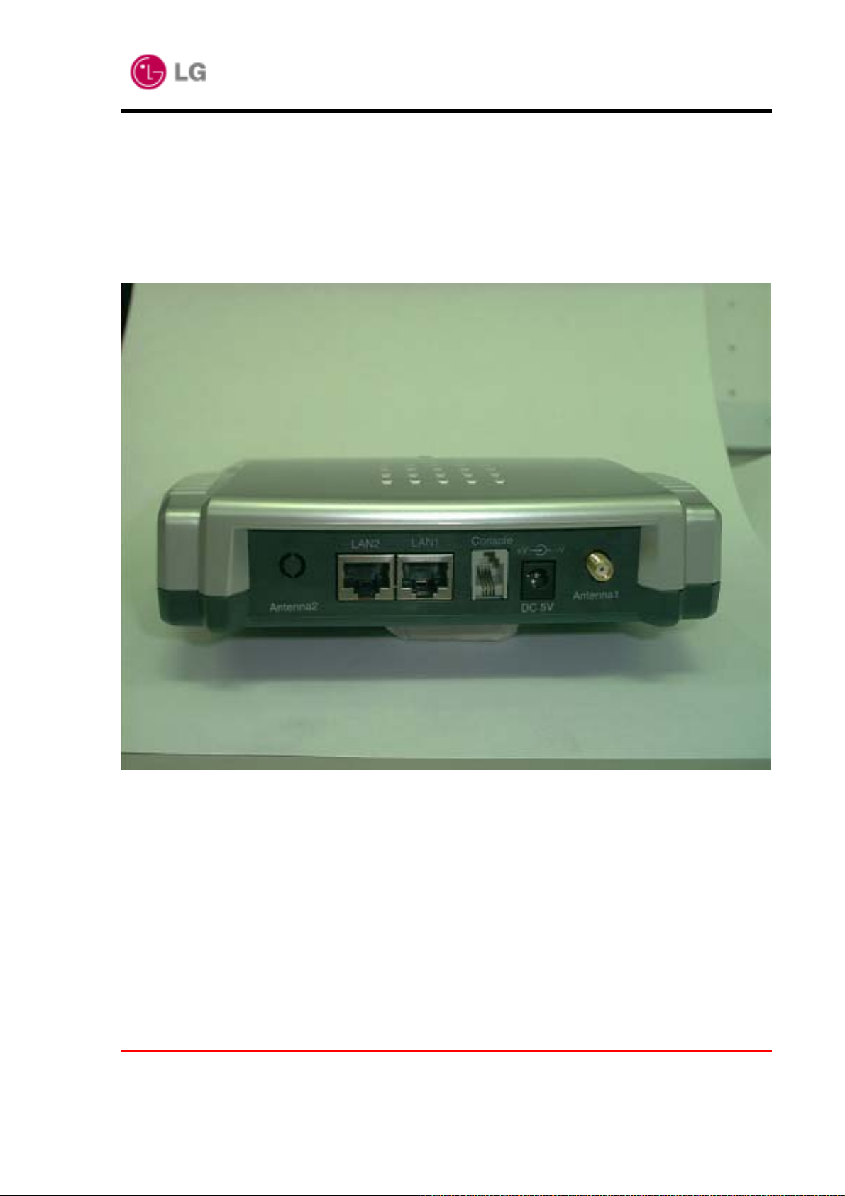
• Rear view
The system is equipped with LAN1 port and LAN2 port for Ethernet interface,
RJ-11 console port for management.
LAN1 : Global Port, RJ-45
10/100Mbps Ethernet to an external Cable/DSL Modem o r LAN Switch/Hub
LAN2 : Local Port, RJ-45, 10Mbps Ethernet
Console : connection to PC COM port.
DC5V : connect the power adapter.
Antenna1 : Dipole Antenna
Antenna2(Optional) : Dipole Antenna
Copyright© 2002 LG Electronics Inc., LTD.
Page 7 of 46
1.1.3. Components
LW2100AP User’s Manual
Version 1.4
2002.05.14
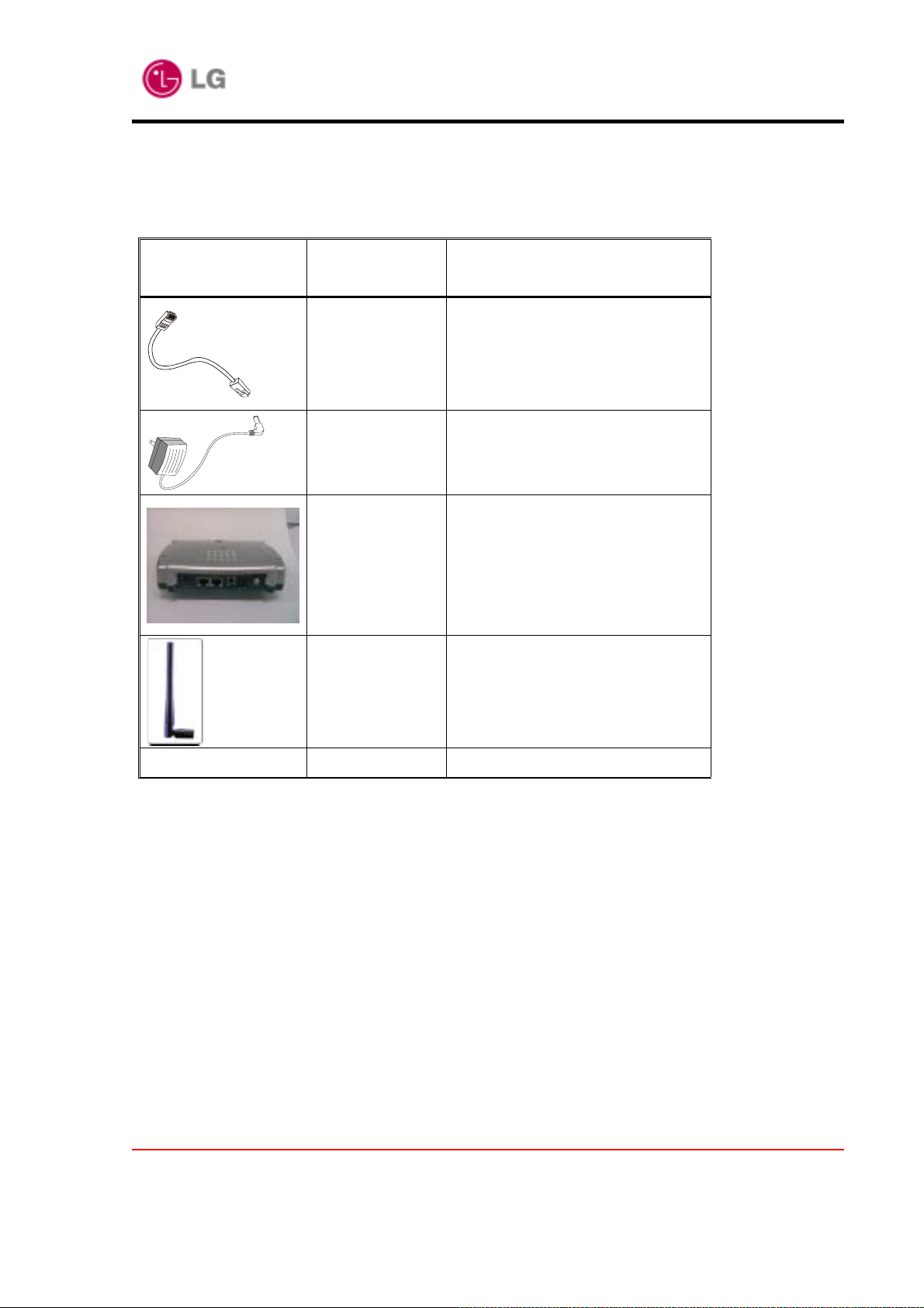
Item Included in
Standard package
Description Purpose
Console cable Connects from console port of
LW2100AP to RS232C Port on PC
Power adapter Connects from LW2100AP to power
source
LW2100AP Main Unit
Antenna
Manuals User’s Guide
Copyright© 2002 LG Electronics Inc., LTD.
Page 8 of 46

LW2100AP User’s Manual
Version 1.4
1.2. Hardware Installation
The configuration information of connected AP is displayed.`
2002.05.14
Internet
ADSL Modem
or Cable Modem
or Uplink HUB
HUB
1. Choose the place with the consideration of power outlet and network connection to inst all
LW2100AP.
2. Use a UTP Ethernet Straight-though cable to connect the DSL/Cable Modem to the
LAN1(Global) port.
3. Use a UTP Ethernet Straight-though Cable to connect the LAN2(Local) port to a free port on
your hub or switch OR Use a Cross-Over cable to connect directly to a PC.
4. Connect the Power Adapter to the DC 5V port on the LW2100AP and into a wall outlet.
Copyright© 2002 LG Electronics Inc., LTD.
Page 9 of 46
LW2100AP User’s Manual
Version 1.4
2002.05.14
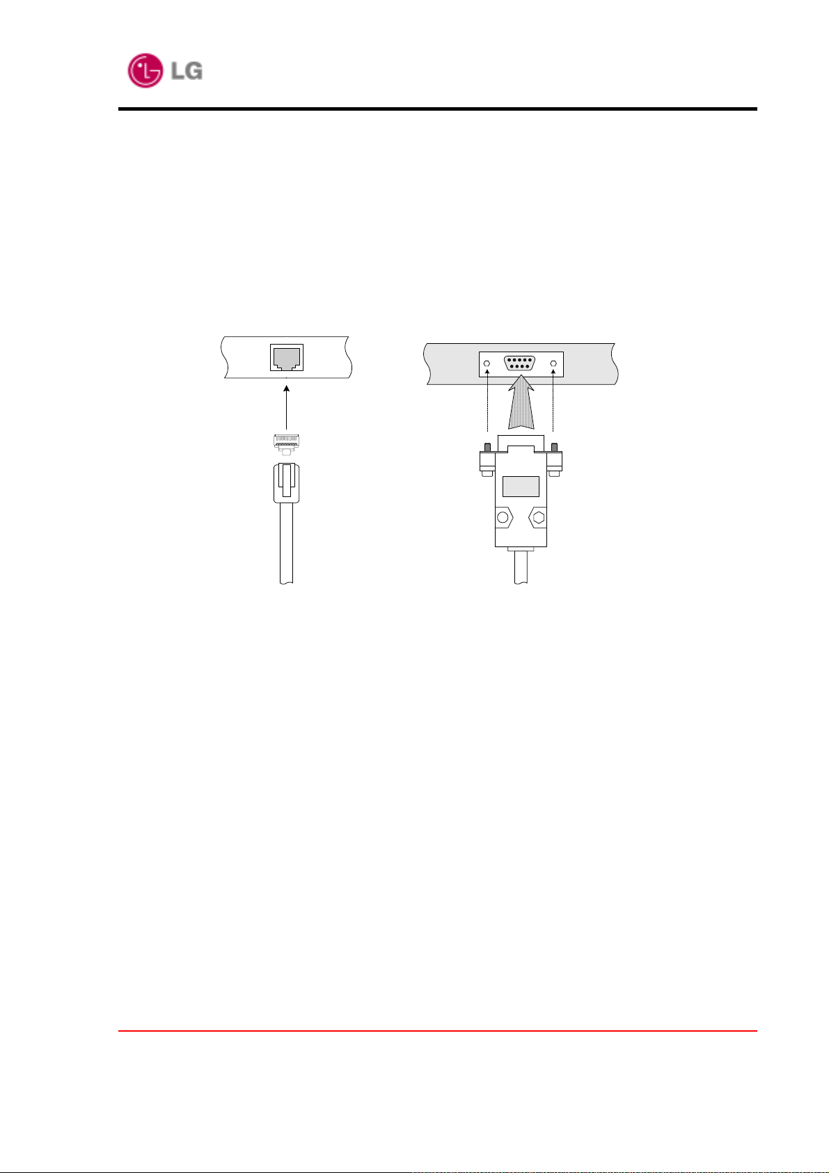
5. onsole cable connection
Using the Console cable included in the package, connect a Seri al port of the administrator
computer to the Console port of LW2100AP. One end of the console cable with the RJ45
connector is connected to the console port on the back panel of the system and the other
end is connected to the 9-pin serial port of a RS-232 based terminal such as workstation, PC
or notebook as shown in the following figure. Then, fix the cable to the AP using the screws
hanging on both sides of the connector.
Router Console Port
Terminal port (male)
Copyright© 2002 LG Electronics Inc., LTD.
Page 10 of 46
LW2100AP User’s Manual
Version 1.4
2002.05.14
1.3. Network Setting for PC
Client machines(PC) require no software, simply set them to accept a dynamically assigned IP
address and reboot. Each time they are powered up the LW2100AP will recognize them and
set their IP address to instantly connect them to the LAN.
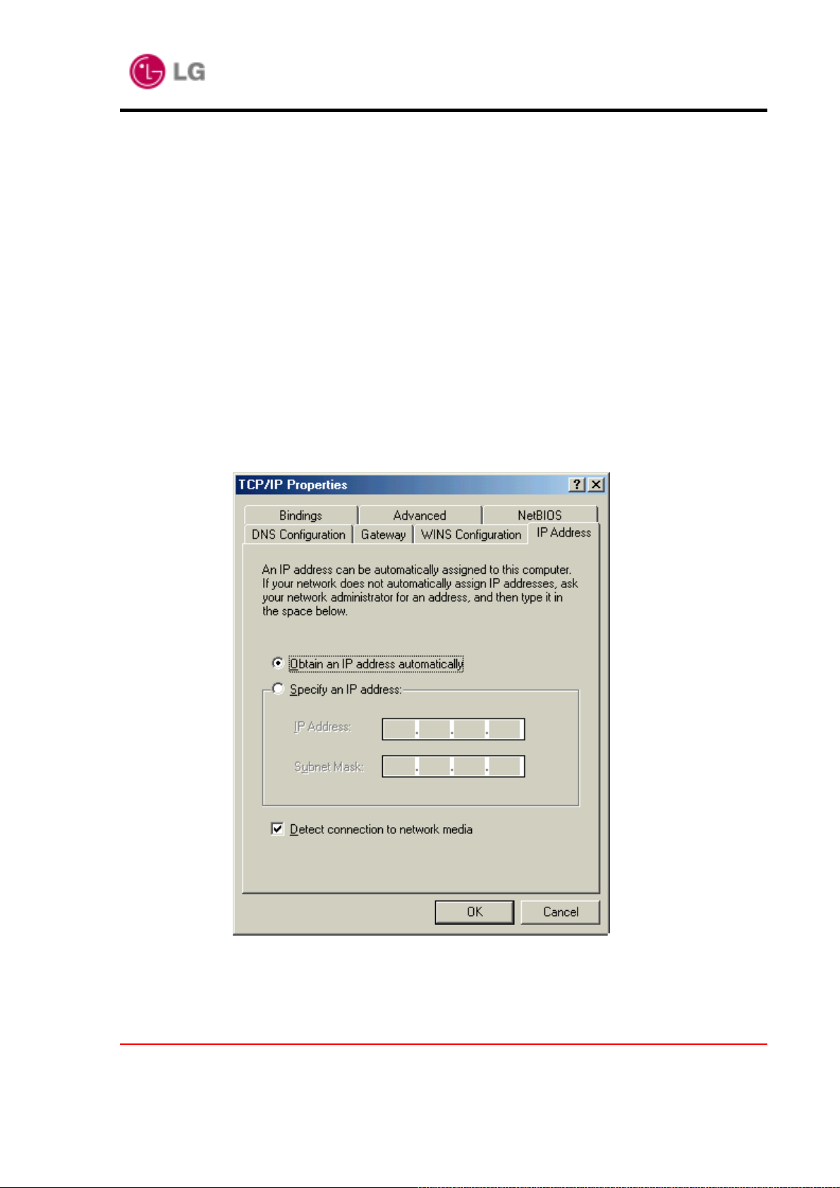
If you want to use an assigned (static) IP address, you can select “Specify an IP address” in
“TCP/IP Properties” window.
How to Set DHCP Client (in Win98)
a. Select Control Panel(Network('TCP/IP' (TCP/IP is only for LGE card). Then the
“TCP/IP Properties” window will be brought to the screen. Click the “IP
Address” tab in the “TCP/IP Properties” window. Select “Obtain an IP address
automatically”. Then reboot the system.
Go into the DOS window to check whether the IP address is normally assigned after the
system reboots. Then execute the command of winipcfg.
Copyright© 2002 LG Electronics Inc., LTD.
Page 11 of 46

LW2100AP User’s Manual
Version 1.4
2002.05.14
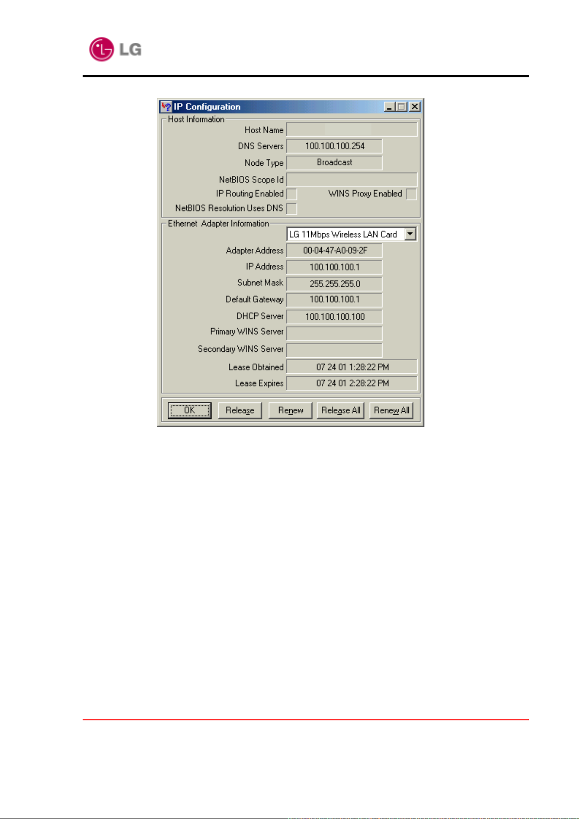
Click the “More Info” button in the “IP Configuration” window as above to view information on IP
Configuration of LGE Wireless LAN Card. Below is the window displayed when you click the
“More Info” button.
Copyright© 2002 LG Electronics Inc., LTD.
Page 12 of 46
LW2100AP User’s Manual
Version 1.4
2002.05.14
Above is the window to show information on IP Address and Subnet Mask assigned by
AP, Default Gateway, DHCP Server, IP Address use time, etc. To be assigned a new IP
Address, click the “Release All” button followed by “Renew All”. The existing IP
address can be re-assigned. In case the existing IP address is already assigned to
another user, you may be re-assigned a different user’s IP address
Copyright© 2002 LG Electronics Inc., LTD.
Page 13 of 46
LW2100AP User’s Manual
Version 1.4
2002.05.14
Chapter 2 WEB Server Manual
2.1 Execution of WEB Server and AP connection to WEB Server
This chapter explains how to connect the LW2100AP to the Internet using Web-based
management tool.
The first step is to execute the Internet browser directly and to enter the IP address of an AP to
connect. At this time, it is possible only if the IP address of an AP to connect is already known.
The default IP address of an AP in factory shipment is 10.0.0.1
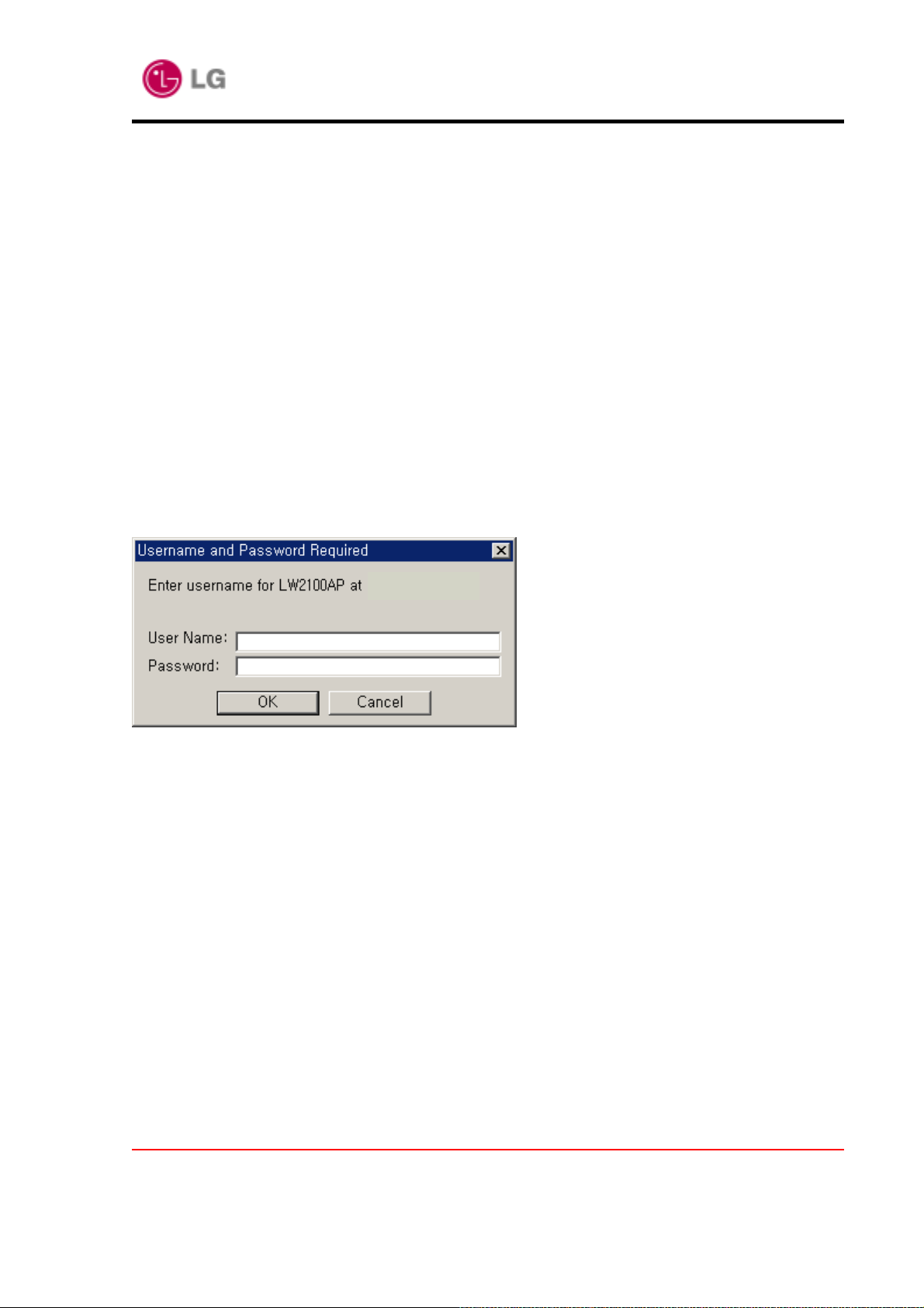
The AP connection to WEB Server is available for a PC that can execute the Internet browser
and connect with the Internet. If the AP connection to WEB Server operates normally, a window
indicating to input the password of connected AP is open.
10.0.0.1
The default value of the username and the password is “root”, “lw2100ap” respectively.
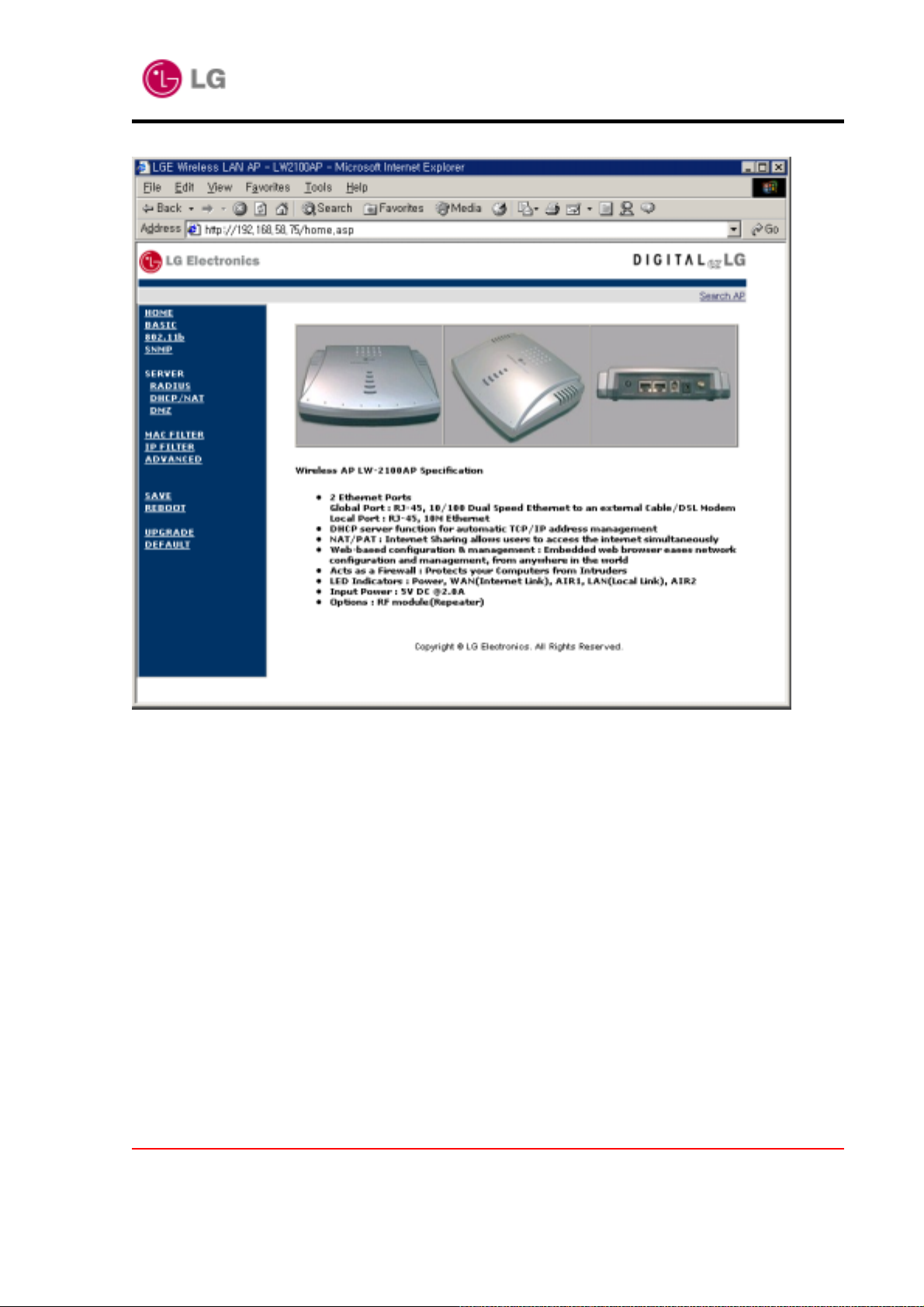
If the password is correctly entered, the initial Home screen displays as follows.
At this time, the access to WEB Server is available.
* The Web-based management system is fully compatible with Microsoft Internet Explorer
versions 4.0 or later and Netscape Communicator versions 4.0 or later. Earlier versions of these
browsers cannot use all features of the management system.
Copyright© 2002 LG Electronics Inc., LTD.
Page 14 of 46
LW2100AP User’s Manual
Version 1.4
2002.05.14
Navigation buttons appear at the left of the page.
You use the navigation buttons to display other management pages
Copyright© 2002 LG Electronics Inc., LTD.
Page 15 of 46

LW2100AP User’s Manual
Version 1.4
2002.05.14
2.2. Menu description of WEB Server
2.2.1. Basic configuration Menu
The Basic configuration Menu displays the Vendor Name, AP name, Password, ESSID, Default
Channel, MAC Address, IP Address, Subnet Mask, and Gateway information of connected AP.
Current System
Vendor Name : The AP system supplier.
AP name : The AP name is not an essential setting, but it helps identify the Access
Point in your network.
Password : Used to change the password of connected AP. Enter a password to
change in “Password” and Retype in “Password Confirm”. The password for Password
and Retype shall be identical. If the password is wrong or not correct, an error message
Copyright© 2002 LG Electronics Inc., LTD.
Page 16 of 46

LW2100AP User’s Manual
Version 1.4
2002.05.14
is displayed and the changed value is not applied.
ESSID: An ID to distinguish the cells of radio LAN network. The clients equipped with
the radio LAN shall be setup with the same ID to make communication with the AP. To
provide the roaming between APs in adjacent area, the SSID of AP in adjacent area
shall be identical. The string used for SSID shall consist of up to 32 alphabets and
figures except blank and special characters (by distinguishing capital and small letters). .
It is setup as “LGE” in factory shipment.
Default Channel: The default channel can be 1 ~ 14 channels. It depends on the
country and in Korea we use 1 ~ 13 channel. If two or more APs are used in adjacent
area, they need to use different channels to avoid the interference. In adjacent area, it is
recommended to set the channels with at least five channels of interval. It is setup as
channel 1 in factory shipment.
AP Mode: Used to determine the AP mode as Access Point or Repeater. In “Access
Point” mode, AP acts as normal AP. In “Repeater” mode, AP acts as wireless repeater
for connecting separated area.
WAN(10/100M) Parameters
WAN(LAN1) Connection Type : IP(for Office LAN user), PPPoE(for ADSL user)
MAC Address: This MAC(Media Access Control) address is a unique serial number
permanently assigned to the Access Point’s WAN Ethernet controller. You cannot
change this MAC Address.
WAN(LAN1) IP Address: Describes the IP address of AP. For the communication with
AP Manager and for the connection with WEB Server and Telnet, it is setup as 10.0.0.1
in factory shipment.
WAN(LAN1) Subnet Mask: Describes the subnet mask of AP. It determines that the IP
Address belongs to which subnet. It is setup as 255.255.255.0 in factory shipment. Upon
changing, user shall inquire of the related person about the matters.
WAN(LAN1) Default Gateway: Describes the default gateway of AP. It is setup as
10.0.0.254 in factory shipment. Upon changing, user shall inquire of the related person
about the matters.
Copyright© 2002 LG Electronics Inc., LTD.
Page 17 of 46

LW2100AP User’s Manual
Version 1.4
2002.05.14
Primary DNS : Enter the IP address of the primary domain name server on your
network. It is setup as 10.0.0.101 in factory shipment. Upon changing, user shall inquire
of the related person about the matters.
Secondary DNS : Enter the IP address of the secondary domain name server on your
network. It is setup as 10.0.0.102 in factory shipment. Upon changing, user shall inquire
of the related person about the matters.
LAN(10M) parameters
MAC Address : This MAC(Media Access Control) address is a unique serial number
Copyright© 2002 LG Electronics Inc., LTD.
Page 18 of 46

LW2100AP User’s Manual
Version 1.4
2002.05.14
permanently assigned to the Access Point’s LAN Ethernet controller. You cannot change
this MAC Address.
LAN(LAN2) IP Address: Describes the IP address of AP. For the communication with
AP Manager and for the connection with WEB Server and Telnet, it is set up as
192.168.0.1 in factory shipment.
LAN(LAN2) Subnet Mask: Describes the subnet mask of AP. It determines that the IP
Address belongs to which subnet. It is set up as 255.255.255.0 in factory shipment.
Upon changing, user shall inquire of the related person about the matters.
Modify : Used to change the item value of Basic Menu. Change the value of each item
in input column and click related button, and then the configuration value will be
changed. However, if the “SAVE” is not performed, the changed value will be returned to
the previous value when AP is rebooted. Refer to the “SAVE” menu.
Cancel : Used to cancel the changed item value of Basic Menu.
Copyright© 2002 LG Electronics Inc., LTD.
Page 19 of 46

LW2100AP User’s Manual
Version 1.4
2002.05.14
2.2.2. 802.11b Menu
The 802.11b Menu displays the WEP related information including WEP use, WEP Generation,
Passphrase, WEP Default Key, Key 1, Key 2, Key 3, Key 4 and others.
WEP: Stands for Wired Equivalent Privacy. It is a function to provide the data security
for the radio communication users and can be set to 64 bits or 128 bits. The web related
information setting for the clients to communicate with related AP should be the same as
that of AP.
WEP Generation: A method to generate the web key. There are the Manual and
Passphrase. In case of Manual, it is to enter directly the web key for generation. In case
of Passphrase, when a word is entered in accordance with the pre-defined method with
the radio LAN, the web key corresponding to the related word will be automatically
Copyright© 2002 LG Electronics Inc., LTD.
Page 20 of 46

LW2100AP User’s Manual
Version 1.4
2002.05.14
generated.
Passphrase: In case the WEB Generation is setup as Passphrase, this is a place to
enter the word for the web key generation.
WEP Default Key: In case the WEB is set to 64 bits, this is the assigned default key. It
can be assigned as 1 ~ 4. In case of 128 bits, it is not necessary to enter.
Key 1, Key2, Key3, Key4 : A place to enter actual key value. Only the HEX values (0~9,
A~F) can be entered. It is possible only if the WEP Generation is Manual.
Basic Rates : The highest rates specified will be the rate that the AP will use when
transmitting broadcast/multicast and management frames.. The rates are expressed in
megabits per second.
Beacon Interval : The amount of time between beacons in kilomicroseconds. One
Kusec equals 1,024 micro seconds.
Copyright© 2002 LG Electronics Inc., LTD.
Page 21 of 46

LW2100AP User’s Manual
Version 1.4
2002.05.14
DTIM : This setting, always a multiple of the beacon period, determines how often the
beacon contains a delivery traffic indication message(DTIM). The DTIM tells power-save
client devices that a packet is waiting for them.
Preamble Mode : The preamble is a section of data at the head of a packet that
contains information the Access Point and client devices need when sending and
receiving packets. A short preamble improves throughput performance.
RTS Threshold(Bytes) : This setting determines the packet size at which the Access
Point issues a request to send(RTS) before sending the packet. Enter a setting ranging
from 0 to 2339 bytes.
Fragmentation Threshold(Bytes) : This setting determines the size at which packets
are fragmented. Enter a setting range from 256 to 2338 bytes. Use a low setting in area
where communication is poor or where there is a great deal of radio interference.
Modify: Used to change the item value of 802.11b Menu. Change the value of each item
in input column and click related button, and then the configuration value will be
changed. However, if the “SAVE” is not performed, the changed value will be returned to
the previous value when AP is rebooted. Refer to the “SAVE” menu.
Cancel: Used to cancel the changed item value of 802.11b Menu.
Copyright© 2002 LG Electronics Inc., LTD.
Page 22 of 46

LW2100AP User’s Manual
Version 1.4
2002.05.14
2.2.3. RADIUS Server Menu
The RADIUS Menu displays information for communication with RADIUS(Remote Authentication
Dial In User Service) server.
RADIUS(Server Use) : Describes whether or not to use the RADIUS Server. “Enable”
shows ‘in use’ of the RADIUS Server and “Disable” shows ‘not use’ of the RADIUS
server.
Authentication Type : Selects the authentication type as MAC, 802.1x, MAC + 802.1x
Primary Authentication Server IP : Shows the IP address of primary RADIUS Server.
Secondary Authentication Server IP : Shows the IP address of secondary RADIUS
Server.
Copyright© 2002 LG Electronics Inc., LTD.
Page 23 of 46

LW2100AP User’s Manual
Version 1.4
2002.05.14
Authentication Server Port : Shows the UDP port number.
Accounting Server IP : Shows the IP address of Accounting Server. Usually same with
RADIUS Server IP address.
Accounting Server Port : Shows the UDP port number .
Shared Secret : Promised authentication value between AP and RADIUS Server.
Available maximum 12 digits in text.
Modify: Used to change the item value of RADIUS Menu. Change the value of each
item in input column and click related button, and then the configuration value will be
changed. However, if the “SAVE” is not performed, the changed value will be returned to
the previous value when AP is rebooted. Refer to the “SAVE” menu.
Cancel: Used to cancel the changed item value of RADIUS Menu.
Copyright© 2002 LG Electronics Inc., LTD.
Page 24 of 46

LW2100AP User’s Manual
Version 1.4
2002.05.14
2.2.4. DHCP/NAT Server Menu
The Server Menu displays DHCP Server information such as Start address, End IP Address,
Lease Duration etc.
The Server Menu displays also whether or not to use NAT Server function.
DHCP Server Use: Describes whether or not the DHCP server of connected AP is used.
“Enable” means ‘in use’ of the DHCP Server and “Disable” means ‘not use’ of the
DHCP Server.
DHCP Lease Start: Shows the start IP address out of the IP address range to be
allocated to the clients when the DHCP Server is in use.
DHCP Lease End: Shows the end IP address out of the IP address range to be
Copyright© 2002 LG Electronics Inc., LTD.
Page 25 of 46

LW2100AP User’s Manual
Version 1.4
2002.05.14
allocated to the clients when the DHCP Server is in use.
DHCP Lease Time: Shows the using period of the IP address to be allocated to the
clients when DHCP Server is in use. The maximum value is 99 days 23 hours 59
minutes.
NAT Server Use : Shows whether or not the NAT function is used. “Enabled” shows ‘in
use’ of the NAT function and “Disabled” shows ‘not use’ of the function.
Modify: Used to change the item value of DHCP/NAT Menu. Change the value of each
item in input column and click related button, and then the configuration value will be
changed. However, if the “SAVE” is not performed, the changed value will be returned
previous value when the AP is rebooted. Refer the “SAVE” menu.
Cancel: Used to cancel the changed item value of DHCP/NAT Menu.
Copyright© 2002 LG Electronics Inc., LTD.
Page 26 of 46

2.2.5. SNMP Server Menu
LW2100AP User’s Manual
Version 1.4
2002.05.14
Contact : The textual identification of the contact person for this AP,
together with information on how to contact this person.
Location : The physical location of this AP (e.g., `telephone closet, 3rd floor').
Read Community : In case of getting request or getting-next request commands are
used for MIB through SNMP, it is used to support minimum security function for the
security of system. Only when the read community name supported in the system and
that of NMS requesting SNMP command are same, the result of the requested MIB is
returned.
Write Community : When the command of set request is used through SNMP, it is used
Copyright© 2002 LG Electronics Inc., LTD.
Page 27 of 46

LW2100AP User’s Manual
Version 1.4
2002.05.14
to support minimum security function for the security of system. Only when the write
community name supported in the system and that of NMS requesting SNMP set
request command are same, the changed value of the requested MIB can be applied to
the system
Trap Manager IP : This is an IP address of NMS that receives SNMP TRAP message
triggered when there is failure in the system. Up to 3 addresses are available.
Modify : Used to change the item value of SNMP Menu. Change the value of each item
in input column and click related button, and then the configuration value will be
changed. However, if the “SAVE” is not performed, the changed value will be returned to
previous value again when the AP is rebooted. Refer to the “SAVE” menu.
Cancel : Used to cancel the changed item value of SNMP Menu.
Copyright© 2002 LG Electronics Inc., LTD.
Page 28 of 46

LW2100AP User’s Manual
Version 1.4
2002.05.14
2.2.6. DMZ Server Menu
The DMZ Server Menu displays static IP address of servers on your LAN using NAT firewall.
Normally NAT firewall filters let unrecognized packets out to protect your LAN.
This function allows you to make a server on your LAN access to internet users.
If users do not want setup DMZ server, then just leave “0” on IP address field. Following
windows show local PC. “192.168.1.21” is FTP server
FTP server : The IP address of FTP server on your LAN.
Modify : Used to change the item value of DMZ Menu. Change the value of each item in
input column and click related button, and then the configuration value will be changed.
However, if the “SAVE” is not performed, the changed value will be returned to previous
value when the AP is rebooted. Refer to the “SAVE” menu.
Cancel : Used to cancel the changed item value of DMZ Menu.
Copyright© 2002 LG Electronics Inc., LTD.
Page 29 of 46

LW2100AP User’s Manual
Version 1.4
2002.05.14
2.2.7. MAC Filter Menu
The MAC Filter Menu displays whether or not to use the MAC Filter function (MAC address
range, MAC address) of connected AP and the MAC Filter related information including the
setting value of each function for use. With this function, it is possible to connect only the PC
equipped with a radio LAN card of registered MAC address to related AP.
In case of a MAC Address registered on both “Allowed MAC Address” and “Denied MAC
Address” then “Denied MAC Address” has priority. In this case the client cannot be associated
with the AP.
MAC Filter : : It is a MAC Filter function to setup the MAC address entering into each
MAC address. Select “Enabled” to setup related function,and select “Disabled” to
release the related function.
Copyright© 2002 LG Electronics Inc., LTD.
Page 30 of 46

LW2100AP User’s Manual
Version 1.4
2002.05.14
MAC Filter Type : It is a MAC Filter function to setup the MAC address entering into the
MAC address range. Select “Allow” to setup related function, and select “Deny” to
release the related function.
Filter 1 ~ 20 MAC Address : It is a MAC Filter function for entering MAC address
each MAC address and to enable/disable only the PC equipped with a radio LAN card
that has related MAC address to be connected to related AP.
Modify: Used to change the item value of MAC Filter Menu. Change the value of each
item in input column and click related button, and then the configuration value will be
changed. However, if the “SAVE” is not performed, the changed value will be returned
previous value when the AP is rebooted. Refer to the “SAVE” menu.
Cancel: Used to cancel the changed item value of MAC Filter Menu.
Copyright© 2002 LG Electronics Inc., LTD.
Page 31 of 46

LW2100AP User’s Manual
Version 1.4
2.2.8. IP Filter Menu
The IP Filter Menu displays whether or not to use the IP Filter function
2002.05.14
FILTER : Use, protocol, port number .
Filter Source IP : Describe the source IP Address.
Filter Source Subnet : Describe the source Subnet mask.
Filter Destination IP : Describe the destination IP Address.
Filter Destination Subnet : Describe the destination Subnet mask.
Apply : Used to change the item value of IP Filter Menu. Change the value of each
item in input column and click related button, and then the configuration value will be
changed. However, if the “SAVE” is not performed, the changed value will be returned
Copyright© 2002 LG Electronics Inc., LTD.
Page 32 of 46

LW2100AP User’s Manual
Version 1.4
previous value when the AP is rebooted. Refer the “SAVE” menu.
Cancel : Used to cancel the changed item value of IP Filter Menu.
2002.05.14
Copyright© 2002 LG Electronics Inc., LTD.
Page 33 of 46

LW2100AP User’s Manual
Version 1.4
2002.05.14
2.2.9 Advanced Menu
User can forward incoming packet to specified local PC, such as H.323 packet. To setup packet
forwarding, user must know TCP/UDP protocol, port number, and local PC IP address.
Following windows show forward incoming TCP/23 packet to local PC “192.168.1.21”.
port : port number
Local IP Address : The IP address of a local PC.
Modify : Used to change the item value of Advanced Menu. Change the value of each
item in input column and click related button, and then the configuration value will be
changed. However, if the “SAVE” is not performed, the changed value will be returned
Copyright© 2002 LG Electronics Inc., LTD.
Page 34 of 46

LW2100AP User’s Manual
Version 1.4
previous value when the AP is rebooted. Refer the “SAVE” menu.
Cancel : Used to cancel the changed item value of Advanced Menu.
2002.05.14
Copyright© 2002 LG Electronics Inc., LTD.
Page 35 of 46

LW2100AP User’s Manual
Version 1.4
2002.05.14
2.2.10. Save Menu
Used to save the changed configurations. However, if the “SAVE” is not performed, the changed
configuration value will be returned previous value when the AP is rebooted.
Copyright© 2002 LG Electronics Inc., LTD.
Page 36 of 46

LW2100AP User’s Manual
Version 1.4
2002.05.14
2.2.11. Reboot Menu
Used to reset connected AP. Click Reboot button. System will be rebooted, and not saved
configuration will be deleted. AP has to be reconnected for web managing.
Copyright© 2002 LG Electronics Inc., LTD.
Page 37 of 46

2.2.12. Upgrade Menu
LW2100AP User’s Manual
Version 1.4
2002.05.14
There is two Boot Method. One is auto and another is manual(method). The difference
is the duration of booting time. Auto method is processed without waiting to enter
bios prompt unconditionally Linux booting is processed. Manual method is processed with
waiting to enter current bios prompt.
Boot File is upgraded firmware image and Boot Server is TFTP Server. TFTP Server
Demon must be installed in Server.(150.150.58.91)
By clicking “the Upgrade Menu”, Firmware upgrade is done.
AP’s system firmware can upgrade by user’s local disk in this page together. After firmware
upgrade in this page, AP will be rebooted to apply new firmware. Before AP’s firmware upgrade,
check console menu to confirm current AP’ firmware version.
Copyright© 2002 LG Electronics Inc., LTD.
Page 38 of 46

LW2100AP User’s Manual
Version 1.4
2002.05.14
2.2.13. Default Value Menu
Used to make the status of connected AP into factory shipment status. Click the Default button.
After defaulting the AP, change the WAN IP Address for reconnecting to AP.
Copyright© 2002 LG Electronics Inc., LTD.
Page 39 of 46

LW2100AP User’s Manual
Version 1.4
2002.05.14
Chapter 3 Console Window Manual
If AP does not include IP address set or is not accessible over the network, you must use
console serial cable to connect PC serial port and AP console port and then set the necessary
items like IP address.
3.1. Connecting Console Window
Execute the HyperTerminal program to access AP by serial port. Although this manual describes
only examples of how to use HyperTerminal program, you are allowed to access AP by different
types of terminal programs. The initial window is executed as below.
Use a random name to access AP and click the “OK”. Then, the “Connect To” window appears:
Copyright© 2002 LG Electronics Inc., LTD.
Page 40 of 46

LW2100AP User’s Manual
Version 1.4
2002.05.14
Select the number to be used to access AP from the serial ports list in the above window. Then
click the “OK” button. A window appears to set various parameters to be used for serial
communications.
Copyright© 2002 LG Electronics Inc., LTD.
Page 41 of 46

LW2100AP User’s Manual
Version 1.4
2002.05.14
To interface with AP, set bit rate per second to “57600”, data bit to “8”, parity to “NO”, stop bit to
“1”, flow control to “NO” and click the “OK” button. Then the initial HyperTerminal window
shows. Press the “Enter” key in the initial window. If you successfully access AP, a window
indicating to input the password of connected AP is opened.
LG Access Point
login: root
Password:
+-----------------------------------------------------------------------------------------------+
| LG LW2100AP |
+-----------------------------------------------------------------------------------------------+
| MENU |
| |
| 1. EZsetup |
| 2. Basic[SYSTEM] |
| 3. Basic[WAN/LAN] |
| 4. IEEE 802.11b |
| 5. SNMP |
| 6. Server[DHCP,NAT,RADIUS] |
| 7. Server[DMZ] |
| 8. MAC Filter |
| 9. IP Filter |
| 0. Advanced |
| |
| COMMAND |
| L(Load)/S(Save)/R(Reboot)/D(Default)/C(Command shell) |
| |
+-----------------------------------------------------------------------------------------------+
| Select Configuration Menu Number / Select Command |
+-----------------------------------------------------------------------------------------------+
Select >
If the password is correctly entered, a prompt provided by AP firmware appears as shown in the window
below. The default value of the password is “lw2100ap”.
Copyright© 2002 LG Electronics Inc., LTD.
Page 42 of 46

LW2100AP User’s Manual
Version 1.4
2002.05.14
3.2. Setting Configuration Elements
Select > 1
When prompted, enter “1” and then press “Enter” key. The current status of the AP set will be
displayed in the window. SSID of AP is set to “LGE” and IP address to “10.0.0.1”by default.
Select > 1
+--------------------------------------------------------------------------------------------------+
| LG LW2100AP |
+--------------------------------------------------------------------------------------------------+
| MENU |
| |
| 1. EZsetup |
| 2. Basic[SYSTEM] |
| 3. Basic[WAN/LAN] |
| 4. IEEE 802.11b |
| 5. SNMP |
| 6. Server[DHCP,NAT,RADIUS] |
| 7. Server[DMZ] |
| 8. MAC Filter |
| 9. IP Filter |
| 0. Advanced |
| |
| COMMAND |
| L(Load)/S(Save)/R(Reboot)/D(Default)/C(Command shell) |
| |
+--------------------------------------------------------------------------------------------------+
| Select Configuration Menu Number / Select Command |
+--------------------------------------------------------------------------------------------------+
Select >c
******************************* NOTICE *****************************************
If you want to setup AP configuration, Type "setup" at command shell
*********************************************************************************
[lgap]#
Copyright© 2002 LG Electronics Inc., LTD.
Page 43 of 46

LW2100AP User’s Manual
Version 1.4
2002.05.14
You may change information on AP configuration in the current Console Window, using the
command number specific to configuration change.
Select >> 1
+------------------------------------------------------------------------------------------------+
| LG LW2100AP |
| |
+------< 1. EZSetup >----------------------------------------------------------------------------+
* AP Name : lgap
* ESSID : network
* Channel : 4
# WAN Connection : IP
* WAN MAC Address : 00:40:5a:93:82:19
* WAN IP Configuration : Static
* WAN IP : 150.150.58.92
* WAN SUBNET : 255.255.255.128
* WAN Gateway : 150.150.58.126
+----------------------------------------------------------------------------------------------+
| Press E(Edit) Key for editing / Press Return Key for Upper Menu |
+-----------------------------------------------------------------------------------------------+
Select >c
******************************* NOTICE *******************************
If you want to setup AP configuration, Type "setup" at command shell
**********************************************************************
[lgap]#
Enter “setup” and then press “Enter” key
Copyright© 2002 LG Electronics Inc., LTD.
Page 44 of 46

LW2100AP User’s Manual
Version 1.4
2002.05.14
[LGAP]# setup
[LGAP]# setup
+----------------------------------------------------------------+
+-----------------------------------------------------------------------------------------------+
| LG Access Point |
| LG LW2100AP |
+---------------------------------------------------------------+
+-----------------------------------------------------------------------------------------------+
| |
| MENU |
| View Configuration |
| |
| |
| 1. SYSTEM |
| 1. EZsetup |
| 2. WAN |
| 2. Basic[SYSTEM] |
| 3. Wireless LAN & LAN |
| 3. Basic[WAN/LAN] |
| 5. IEEE 802.11b |
| 4. IEEE 802.11b |
| 6. RADIUS |
| 5. SNMP |
| 7. DHCP & NAT |
| 6. Server[DHCP,NAT,RADIUS] |
| 8. SNMP |
| 9. Filter(IP & MAC) |
| 7. Server[DMZ] |
| 0. etc. |
| 8. MAC Filter |
| S. Set Configuration |
| 9. IP Filter |
| Q. exit |
| 0. Advanced |
+---------------------------------------------------------------+
| |
| Select Configuration Menu... |
+---------------------------------------------------------------+
| COMMAND |
| L(Load)/S(Save)/R(Reboot)/D(Default)/C(Command shell) |
Select >> 1
| |
+-----------------------------------------------------------------------------------------------+
| Select Configuration Menu Number / Select Command |
+-----------------------------------------------------------------------------------------------+
Select >> 1
Copyright© 2002 LG Electronics Inc., LTD.
Page 45 of 46

LW2100AP User’s Manual
Version 1.4
2002.05.14
Caution
Be careful to define the value(s) and item(s) that you want to change as long as
any change in AP configuration may seriously affect terminal system connected
to AP.
7
Copyright© 2002 LG Electronics Inc., LTD.
Page 46 of 46
 Loading...