

LG LVUB2460RL Installation Manual
ENGLISH
1
2
3
4
10
11
12
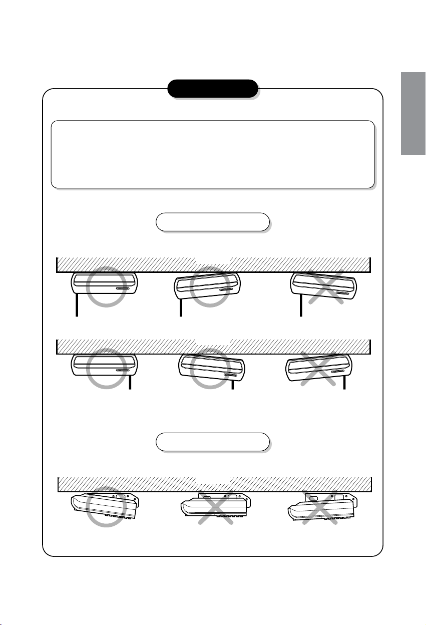
(Ceiling/Wall Mounting)
(Floor Mounting)
5
6
more than�
10cm
more than�
70cm
more than�
10cm
more than�
10cm
9
8
7
CONVERTIBLE TYPE AIR CONDITIONERS
INSTALLATION INSTRUCTIONS
(Refrigerant : R-410A)
• This unit is charged with new refrigerant, R-410A.
• Be sure to use proper tools for R-410A, when installing the unit.
• Please read this instruction sheet completely before installing the product.
• When the power cord is damaged, replacement work shall be performed by authorized personnel only.
• Installation work must be performed in accordance with the national wiring standards by authorized
personnel only.
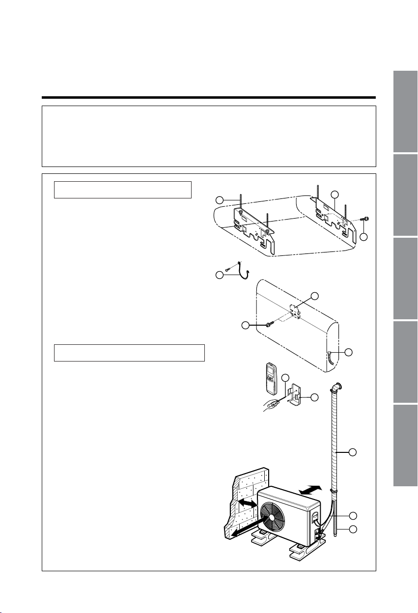
① Installation Plate (2pcs)
② Washer Bolt (M8×L25, 4pcs, type "A”)
③ Floor Mount Bracket (1pcs)
④ Drain Hose, Insulated
⑤ Remocon Holder
⑥ Screw for Remocon Holder(type "B")
⑦ Drain Hose Hanger and screw
⑧ Suspension Bolt
⑨ Bolts for Mount Bracket
⑩ Connecting Tube
• Gas side : Ø12.7
• Liquid side : Ø6.35
⑪ Connecting Cable
⑫ Drain Hose Extended
P/No. : 3828A30064Z
Installation Parts Provided
The other Installation Parts Needed
ITALIANO
ESPAÑOL FRANÇAIS
DEUTSCH

2
OUT-LINE OF INSTALLATION
1.The following should be always observed for safety .........................................3
2. Installation of Indoor, Outdoor unit
3. Connecting Pipes to the Indoor Unit
4. Connecting Pipes to the Outdoor Unit
5. Checking the Drainage .......................................................................................15
6. Connecting Cables between Indoor Unit and Outdoor Unit
7. Air Purging of Pipes and Indoor Unit ...............................................................19
8. Test running
Installation works Installation Parts Required tools
1)
Selection of the best
location
..........................4
2) Indoor unit installation ......5
Installation on the ceiling..5
Installation on the wall......9
Installation on the floor ...11
•
Installation Plate
•
Four Type “A” screws
•
Connecting cable
•
Level
•
Screw driver
•
Electric drill
•
Hole core drill (ø70mm)
1) Preparation of Piping......12
2) Installation on the ceiling13
3) Installation on the wall or
floor.....................................14
•
Pipes: Gas side .....1/2"
Liquid side .............1/4"
•
Insulated drain hose
•
Insulation materials
•
Flaring Tools set
•
Specified Torque Wrenches
1.8kg·m ......
Liquid side piping
5.5kg·m ......... Gas side piping
Spanner ................. Half union
..
1) Connecting the pipes to the
Outdoor Unit...................15
•
Additional Drain hose
(Outer Dia...............15.5mm)
•
Specified Torque Wrenches
1.8kg·m ......
Liquid side piping
5.5kg·m ......... Gas side piping
1) Connection of power supply.
............................................21
2) Evaluation of the
performance .......................21
•
Two type “B” screws
•
Ownerʼs Manual
•
Thermometer
1) Connecting cables to the
Indoor Unit......................16
2) Connecting cables to the
Outdoor Unit...................17
3) Form the pipings.............18
•
Screw driver
•
Hexagonal Wrench (4mm)
•
Gas-leak Detector
ENGLISH
3
1. The following should always be observed for safety
• Please report to or take consent by the supply authority before connection to the system.
• Be sure to read "THE FOLLOWING SHOULD ALWAYS BE OBSERVED FOR SAFETY" before installing
the air conditioner.
• Be sure to observe the cautions specified here as they include important items related to safety.
• The indications and meanings are as follows.
• After reading this manual, be sure to keep it together with the instruction manual in a handy place on the
customer's site.
Could lead to death, serious injury, etc.
Could lead to serious injury in particular environments when operated
incorrectly.
WARNING
CAUTION
Do not install it yourself (customer).
• Incomplete installation could cause injury due to fire, electric
shock, the unit falling or a leakage of water. Consult the dealer
from whom you purchased the unit or special installer.
Perform the drainage/piping work securely
according to the installation manual.
• If there is a defect in the drainage/piping work, water
could drop from the unit and household goods could
be wet and damaged.
Do not install the unit in a place where an
inflammable gas leaks.
• If gas leaks and accumulates in the area
surrounding the unit, it could cause an explosion.
Perform the installation securely referring to the installation manual.
• Incomplete installation could cause a personal
injury due to fire, electric shock, the unit falling
or a leakage of water.
Install the unit securely in a place which can bear
the weight of the unit.
• When installed in an insufficient strong place,
the unit could fall causing injured.
Use the specified wires to connect the indoor and outdoor
units securely and attach the wires firmly to the terminal
board connecting sections so the stress of the wires is not
applied to the sections.
• Incomplete connecting and fixing could cause fire.
Check that the refrigerant gas due not leak
after installation is completed.
Perform electrical work according to the installation
manual and be sure to use an exclusive circuit.
• If the capacity of the power circuit is insufficient
or there is incomplete electrical work, it could
result in a fire or an electric shock.
Attach the electrical part cover to the indoor unit
and the service panel to the outdoor unit securely.
• If the electrical part cover if the indoor unit and/or the service
panel if the outdoor unit are not attached securely, it could
result in a fire or electric shock due to dust, water, etc.
Be sure to use the part provided or specified parts for the
installation work.
• The use of defective parts could cause an injury or leakage
of water due to a fire, electric shock, the unit falling, etc.
WARNING
CAUTION
2. Installation of Indoor, Outdoor unit
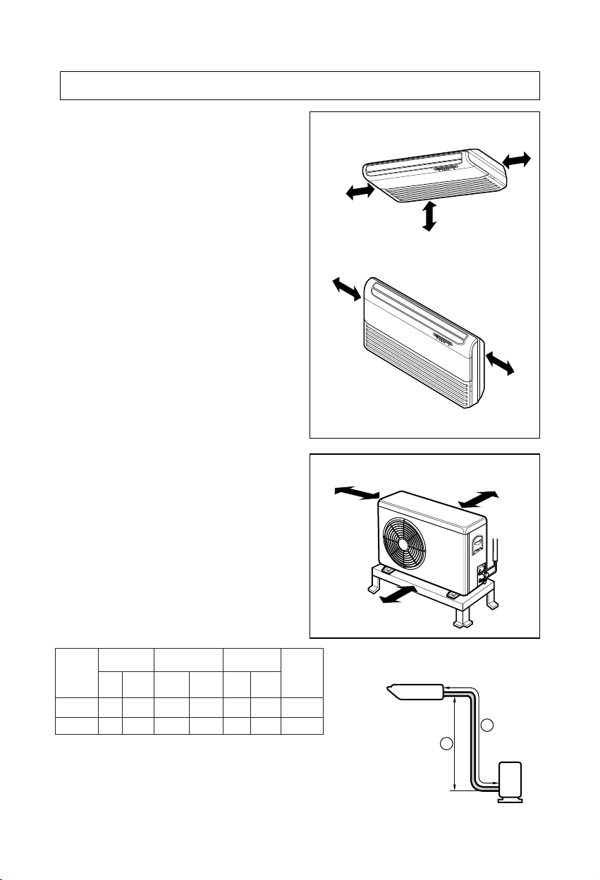
1. Selection of the best location
1) Indoor unit
• There should not be any heat source or steam
near the unit.
• There should not be any obstacles to prevent
the air circulation.
• A place where air circulation in the room will be
good.
• A place where drainage can be easily obtained.
• A place where noise prevention is taken into
consideration.
• Do not install the unit near the door way.
• Ensure the spaces indicated by arrows from the
wall, ceiling, or other obstacles.
2) Outdoor unit
• If an awning is built over the unit to prevent
direct sunlight or rain exposure, be careful that
heat radiation from the condenser is not
restricted.
• There should not be any animals or plants which
could be affected by hot air discharged.
• Ensure the spaces indicated by arrows from the
wall, ceiling, fence or other obstacles.
3) Piping length and the elevation
• If 18K or 24K Model is installed at a distance of 15m, 240g of refrigerant should
be added........................................................................................(15-7)x30g
4
More than
20cm
More than eye-level
More than
20cm
R
R
More than
20cm
More than
20cm
(Ceiling installation)
(Floor/Wall installation)
More than 10cm
More than 10cm
More than 70cm
Indoor unit
Outdoor unit
B
A
MODEL
18K BTU
1/2"
1/2"
1/4" 7 15
24K BTU
1/4" 7 20
GAS LIQUID
58 30
58 30
Elevation B(m)
Length A(m)
* Additional
refrigerant
(g/m)
Pipe Size
Rated Rated
Max. Max.
ENGLISH
5
1076
Suspension
bolt
Center-line for the
piping hole
265
1236
265
Install Plate
1)
2)
Side Plate
Inlet Grille
Inlet hanger
Hanger
screw
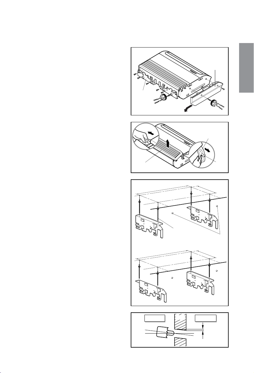
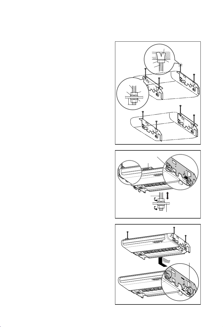
2. Indoor unit installation
■
Before Installing, prepare Installation Plates
• 'Installation Plates' are attached at the bottom
of indoor unit.
Detach them by removing each 3 screws at
both sides.
• Detach 'Side Plate (R,L)' by removing each 2
screws on both sides.
• Pull the upper right and left side of 'Inlet Grille'
to the front, and it will stop at slightly tilted
position.
• Unhook the 'Inlet hanger' from the 'Hanger
screw' on the both left and right side.
• Detach the 'Inlet Grille' from the Indoor Unit.
1) Installation on the ceiling
• Measure and mark the position for the
Suspension bolts and the piping hole.
• Drill the hole for anchor nut on the ceiling.
※ Before secure the Installation Plates,
select the bent direction of the Installion
Plate to the inside or the outside according
to the installation circumstances.
• Drill the piping hole on the wall slightly tilted to
the outdoor side using a ø70 hole-core drill.
Indoor Outdoor
WALL
5~7mm
6
Washer
Nut
Suspension
bolts
Ceiling
Anchor nut
Suspension
bolts
Spring
washer
Max.
12mm
Washer
Nut
1)
2)
Suspension
bolt
Installation plate
Adjust a level
R
Level gauge
Lower slot
R
R
Upper slot
• Insert the nuts and washer onto the suspension
bolts for locking the suspension bolts on the
ceiling.
• Mount the suspension bolts to the anchor-nuts
firmly.
• Secure the Installation plates onto the
Suspension bolts (adjust level roughly.) using
nuts, washers and spring washers.
• Engage 2 hooks on the both left and right side
of the unit to the lower slot of Installation
Plates.
• Adjust a level with a level gauge on the
direction of left-right, back-forth by adjusting
suspension bolts.
• Move the hooks on the unit to the upper slot of
Installation Plates. Then the unit will be
declined to the bottomside so as to drain well.
7
Drain hose
Ceiling
Ceiling
CAUTION
Ceiling
ENGLISH
1. Install declination of the indoor unit is very important for the drain of the
convertible type air conditioner.
2. Minimum thickness of the insulation for the connecting pipe shall be 7mm.
3. If the Installation Plates are fixed to horizontal line, the indoor unit after installing
will be declined to the bottomside.
Front of view
• The unit must be horizontal or declined to the drain hose connected when finished
installation.
• The unit must be declined to the bottomside of the unit when finished installation.
Side of view
 Loading...