


LG Video Camera
Instruction Manual
Models : LVC-SX810HM/HP
Before installing, operating or adjusting this
product, please read this instruction booklet
carefully and completely.
LVC-SX810HM_HP_ENG_77T 6/13/07 3:41 PM Page 1

2
This lightning flash with arrowhead symbol within an equilateral triangle is intended to alert the user to the presence of uninsulated dangerous voltage within the product’s enclosure that may be of sufficient magnitude to
constitute a risk of electric shock to persons.
The exclamation point within an equilateral triangle is
intended to alert the user to the presence of important
operating and maintenance (servicing) instructions in the
literature accompanying the product.
FCC WARNING : This equipment may generate or use radio frequency energy. Changes or modifications to this equipment may cause
harmful interference unless the modifications are expressly approved
in the instruction manual. The user could lose the authority to operate
this equipment if an unauthorized change or modification is made.
Regulatory Notices For U.S.A
This equipment has been tested and found to comply with the limits
for a Class A digital device, pursuant to Part 15 of the FCC Rules.
These limits are designed to provide reasonable protection against
harmful interference when the equipment is operated in a commercial
environment.
This equipment generates, uses, and can radiate radio frequency
energy and, if not installed and used in accordance with the instruction
manual, may cause harmful interference to radio communications.
Operation of this equipment in a residential area is likely to cause
harmful interference in which case the user will be required to correct
the interference at his own expense.
• A suitable conduit entries, knock-outs or glands shall be provided in
the cable entries of this product in the end user.
• Caution: Danger of explosion if battery is incorrectly replaced.
Replaced only with the same or equivalent type recommended by
the manufacturer. Dispose of used batteries according to the manufacturer’s instructions.
• Holes in metal, through which insulated wires pass, shall have
smooth well rounded surfaces or shall be provided with brushings.
Warning: Do not install this equipment in a confined space such as a
bookcase or similar unit.
Warning: Wiring methods shall be in accordance with the National
Electric Code, ANSI/NFPA 70.
Warning: This is a class A product. In a domestic environment this
product may cause radio interference in which case the user may be
required to take adequate measures.
Warning: To reduce a risk of fire or electric shock, do not expose this
product to rain or moisture.
Caution: This installation should be made by a qualified service person and should conform to all local codes.
Caution: To avoid electrical shock, do not open the cabinet. Refer
servicing to qualified personnel only.
Caution: The apparatus should not be exposed to water (dripping or
splashing) and no objects filled with liquids, such as vases, should be
placed on the apparatus.
CAUTION: TO REDUCE THE RISK OF ELECTRIC SHOCK
DO NOT REMOVE COVER (OR BACK)
NO USER-SERVICEABLE PARTS INSIDE
REFER SERVICING TO QUALIFIED SERVICE PERSONNEL.
CAUTION
RISK OF ELECTRIC SHOCK
DO NOT OPEN
LVC-SX810HM_HP_ENG_77T 6/13/07 3:41 PM Page 2

3
Important Safety Instructions
1. Read these instructions. - All these safety
and operating instructions should be read
before the product is operated.
2. Keep these instructions. - The safety, operat-
ing and use instructions should be retained for
future reference.
3. Heed all warnings. - All warnings on the prod-
uct and in the operating instructions should be
adhered to.
4. Follow all instructions. - All operating and
use instructions should be followed.
5. Do not use this apparatus near water. - For
example: near a bath tub, wash bowl, kitchen
sink, laundry tub, in a wet basement; near a
swimming pool; etc.
6. Clean only with dry cloth. - Unplug this prod-
uct from the wall outlet before cleaning. Do not
use liquid cleaners.
7. Do not block any ventilation openings.
Install in accordance with the manufacturer’s instructions. - Slots and openings in the
cabinet are provided for ventilation, to ensure
reliable operation of the product, and to protect
it from over- heating. The openings should
never be blocked by placing the product on a
bed, sofa, rug or other similar surface. This
product should not be placed in a built-in installation such as a bookcase or rack unless proper ventilation is provided and the manufacturer’s instructions have been adhered to.
8. Do not install near any heat sources such
as radiators, heat registers, stoves, or other
apparatus (including amplifiers) that produce heat.
LVC-SX810HM_HP_ENG_77T 6/13/07 3:41 PM Page 3
4
Important Safety Instructions
9. Do not defeat the safety purpose of the
polarized or grounding-type plug. A polarized plug has two blades with one wider
than the other. A grounding type plug has
two blades and a third grounding prong.
The wide blade or the third prong are provided for your safety. If the provided plug
does not fit into your outlet, consult an
electrician for replacement of the obsolete
outlet.
10. Protect the power cord from being walked
on or pinched particularly at plugs,
convenience receptacles, and the point
where they exit from the apparatus.
11. Only use attachments/accessories specified by the manufacturer.
12. Use only the cart, stand,
tripod, bracket, or table
specified by the manufacturer, or sold with
apparatus. When a cart is
used, use caution when
moving the cart/ apparatus combination to avoid injury from tipover.
13. Unplug this apparatus during lightning
storms or when unused for long periods
of time.
14. Refer all servicing to qualified service personnel. Servicing is required when the
apparatus has been damaged in any way,
such as power- supply cord or plug is
damaged, liquid has been spilled or
objects have fallen into the apparatus, the
apparatus has been exposed to rain or
moisture, does not operate normally, or
has been dropped.
LVC-SX810HM_HP_ENG_77T 6/13/07 3:41 PM Page 4

5
Contents and Features
Contents
Part Names and Functions . . . . . . . . . . . . . . .6-7
Connections . . . . . . . . . . . . . . . . . . . . . . . .8
Mounting the Lens . . . . . . . . . . . . . . . . . .9-10
Concerning Auto-Iris Lenses . . . . . . . . . . .11-12
Function Switch Settings . . . . . . . . . . . . . . . .13
Day&Night Function Settings . . . . . . . . . . .14-15
Flange-back Adjustment . . . . . . . . . . . . . . . .16
Installation of Camera . . . . . . . . . . . . . . . . .17
Specifications . . . . . . . . . . . . . . . . . . . . .18-19
Features
This color video camera is designed for use in monitoring system.
• High resolution and high sensitivity with a 1/3
inch Super HAD CCD (Charge Coupled Device)
• CS Mount (Adapter Ring Mount for C Lens:
Optional)
• The input power source is DC 12V (4.5W (Max)).
Maintenance of the unit
• Remove dust or dirt on the surface of the lens
with a blower.
• Use a dry soft cloth to clean the body. If it is
very dirty, use a cloth dampended with a small
quantity of neutral detergent and then wipe dry.
• Avoid the use of volatile solvents such as thin-
ners, alcohol, benzene, and insecticides. They
may damage the surface of the body.
LVC-SX810HM_HP_ENG_77T 6/13/07 3:41 PM Page 5
6
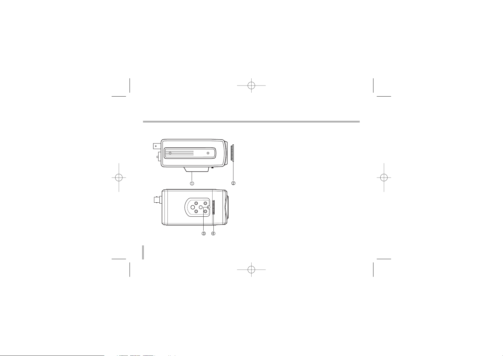
Part Names and Functions
1. Camera mounting bracket
The bracket can be fixed at the top or bottom
of the camera. (page 17)
2. Lens mount cap
The cap is installed to protect the lens mount
section. Remove the lens mount cap before
installing a lens (sold separately).
3. Flange-back lock screw
4. Flange-back adjustment dial
LVC-SX810HM_HP_ENG_77T 6/13/07 3:41 PM Page 6

7
Part Names and Functions
5. Power indicator
Comes on when the power to the camera is on.
6. Power input terminal
DC 12 V input terminal.
This camera must always be operated a DC 12 V
Certified/Listed, class 2 power supply only.
7. D&N connector for manual setting
8. Video output connector (BNC type)
Connect this connector to a device such as a
VCR or monitor with a VIDEO IN connector.
9. Function switches for manual setting
To set functions, use these dip switches.
10. Lens iris output connector (LENS)
This 4- pin connector is used to send the Iris
control signal and power supply to an auto-iris
type lens.
11. DC iris level adjustment volume
12. ALC Lens Setting Switch
DC: When you attach an Auto Iris lens requir-
ing the DC control signal, please put this
switch in the DC position.
ELC: When you attach a manual or fixed lens,
please put this switch in the ELC position.
VIDEO: When you attach an Auto Iris lens
requiring the video control signal, please put
this switch in the VIDEO position.
LVC-SX810HM_HP_ENG_77T 6/13/07 3:41 PM Page 7

8
Connections
Basic connection
The peripheral devices (VCR, monitor, lens, etc.),
AC adaptor and cables are not supplied.
1. Connecting the monitor
Make the video signal connection between the
camera and the monitor or time lapse VCR.
2. Use a commercially available
Certified/Listed, Class 2, DC 12 V adaptor.
Connect an DC 12 V power source to the DC
12V input terminal on the back of the camera
with 3 and # aligned correctly as shown left.
3. Insert the plug of this power cord into a wall
outlet.
The POWER indicator will light.
1
2
3
LVC-SX810HM_HP_ENG_77T 6/13/07 3:41 PM Page 8

9
Mounting the Lens
1. Remove the lens mount cap from the camera.
2. Install the auto-iris lens.
2-1. CS mount type lens
Carefully align the lens mount with the camera
opening, then turn the lens slowly to install it.
2-2. C mount type lens
To allow for flange- back adjustment, install the
C-mount adaptor (option) on the lens mount,
then carefully align the lens mount with the
camera opening and turn the lens slowly to
install it.
3. Connect the lens plug to the lens iris output
connector (LENS) on the back of the camera.
When using lenses from other makers, the plug
shape may not correspond to the terminal on
the camera.
In such a case, remove the original plug and
using a soldering iron, connect a lens iris plug
according to the diagram. (Refer to next page.)
1
2-1
2-2
3
LVC-SX810HM_HP_ENG_77T 6/13/07 3:41 PM Page 9

10
Mounting the Lens
Pin layout for the lens iris output connector
No. DC type lenses VIDEO type lenses
1 Damping - Vcc (+9V)
2 Damping + Not used
3 Drive + Video
4 Drive - Ground
Rewire the lens iris plug
1. Cut off the plug of the lens cable, cut off
approximately 8mm of the insulation, and then
strip approximately 2mm of the ends of the
cable sheaths.
2. Solder the ends of the cable wires to the ends
of the pins, and then attach the cover of the
lens iris plug.
8mm
2mm
LVC-SX810HM_HP_ENG_77T 6/13/07 3:41 PM Page 10

11
Concerning Auto-Iris Lenses
DC type auto-iris lens
A lens without driver circuit that operates only on
a DC power source. In general, this type of lens is
referred to as DC type coil lens. (Set the ALC Lens
Setting Switch to the DC position.)
CAUTION :
Depending on the type of lens used, the lens
may not perform properly. In such a case, adjust the LEVEL
volume on the lens casing to correct.
ELC type auto-iris lens
Use a manual or fixed iris lens (Set the ALC Lens
Setting Switch to the ELC position.)
LVC-SX810HM_HP_ENG_77T 6/13/07 3:41 PM Page 11

12
Concerning Auto-Iris Lenses
VIDEO type auto-iris lens
A lens with amplifier circuit that operates on video
signal and DC power source. In general, this type of
lens is referred to as EE amplifier type lens.
ALC and LEVEL volume level controls are available
on the lens for iris adjustments. (Set the ALC Lens
Setting Switch to the VIDEO position.)
CAUTION :
Be cautions not to use Auto Iris Lens with over 30mA.
Notes :
• Set the ALC and LEVEL controls on the lens to adjust the
iris. Normally the ALC volume should be turned all the way
to Av (Average).
•
Depending on the type of lens used, the lens may not
perform properly. In such a case, adjust the LEVEL volume on the lens casing to correct.
ALC LEVEL
ALC volume
level control
LEVEL volume
level control
LVC-SX810HM_HP_ENG_77T 6/13/07 3:41 PM Page 12

13
Function Switch Settings
No Name Position Function Effect
AWB
HOLD
ON
OFF
ON
OFF
ON
OFF
D&N AUTO
D&N MAN
Auto tracking White Balance
White Balance Hold
AGC level varies from 10dB to
maximum 30dB
10dB (Max.)
Sets to this position when strong
light comes in behind the target
Normal position
Shutter speed is fixed.
(NTSC : 1/100 sec, PAL : 1/120 sec)
Shutter speed is not fixed
Auto mode
Manual mode
1 White Balance
2AGC
(Auto Gain Control)
3 BLC
(Back Light
Compensation)
4FL
(Flickerless)
5 D&N
(Day & Night)
* Factory Setting
Note: When you switching the D&N function, noise may appears on the
screen while changing filter.
LVC-SX810HM_HP_ENG_77T 6/13/07 3:41 PM Page 13

14
Day&Night Function Settings
Auto Mode
The D&N function is activated automatically AGC
ON mode.
Set the D&N dip switch to D&N AUTO position on
the rear panel.
Notes :
• It is not necessary to connect the D&N terminal to con-
trol D&N auto function.
• If you use the IR illumination, the Day and Night func-
tion may be switch again and again. In this case, use
the manual mode or Night Lock function.
Night Lock function in Auto mode
The D&N Auto function is fixed to night mode.
Close the connected External S/W for this funciton.
Note :
If you disconnet the external S/W from the D&N terminal,
the D&N function is set to auto mode.
LVC-SX810HM_HP_ENG_77T 6/13/07 3:41 PM Page 14
Close
External S/W

15
Day&Night Function Settings
Manual Mode
You can set the D&N function manually.
1. Set the D&N dip switch to D&N MAN position on
the rear panel.
2. Connect an external S/W to D&N terminal on the
rear panel.
Day function
When you open the external S/W, the D&N funciton
is set to Day mode.
Night function
When you close the external S/W, the D&N funciton
is set to night mode.
Open
External S/W
Close
External S/W
LVC-SX810HM_HP_ENG_77T 6/13/07 3:41 PM Page 15

16
Flange-back Adjustment
The adjustment is required only when a lens without focus-adjusting mechanism is mounted, or
when a lens with adjusting mechanism is mounted
and focus that is more accurate is needed.
1 Loosen the flange-back fixing screw on the
flange-back adjusting ring.
2. Turn the flange-back adjusting ring to obtain a
focused point while watching the monitor
screen.
3. Tighten the flange-back fixing screw on the
flange-back adjusting ring.
Caution:
Tightening the screw by force will cause damage to
the screw or deviation of focus.
Note: The object may be out of focus when using a
source of near-infrared light than using the visible
light.
flange-back
fixing screw
flange-back
adjusting ring
LVC-SX810HM_HP_ENG_77T 6/13/07 3:41 PM Page 16

17
Installation of Camera
The bracket (optional) can be installed to either
the top of the camera as desired. When changing
the position of the camera mounting bracket, you
should always reuse the screws that have been
removed.
Notes:
•
If using a camera mounting bracket, select a
location that is strong enough to bear the full
weight of the camera and the mounting bracket
for long periods, and install the camera and
mounting bracket securely.
•
The camera has not been evaluated for wall or
ceiling mounting.
LVC-SX810HM_HP_ENG_77T 6/13/07 3:41 PM Page 17

Model LVC-SX810HM LVC-SX810HP
Signal System NTSC PAL
Total/Effective Pixels 410K/380K 470K/440K
Pick-Up Device 1/3 - Inch Interline Color CCD(Super HAD)
Lens C / CS MOUNT (Adapter Ring Mount for C Lens: Optional)
Iris Control DC / ELC / VIDEO
Signal Process Digital Signal Process
Scanning System 2:1 Interlace
Sync. System Internal
Scanning Frequency 59.94Hz(VD) 50Hz(VD)
Resolution 500Lines
S/N Ratio More than 50 dB
Standard Illuminance 2000Lux (3200°K)
Sensitivity (1/3 Output) 0.4Lux (F1.0), 0Lux (Infrared ON : Night Mode)
Video Output Signal 1Vp-p Composite (75Ω)
Day & Night Auto / Manual / EXT
Back Light Manual ON / OFF (with DIP Switch)
18
Specifications
LVC-SX810HM_HP_ENG_77T 6/13/07 3:41 PM Page 18

19
Specifications
Model LVC-SX810HM LVC-SX810HP
Gain Control ON (Max. 30dB) / OFF (Max.10dB) (with DIP Switch)
Flickerless ON / OFF (with DIP Switch)
White Balance AWB / Hold (White Balance Hold)
Exposure Automatic control with DC Iris meter / Video Iris meter
/ Auto Electronic Shutter (Max. 1/100000)
Power Source DC 12V ± 10%
Power Consumption 4.5W (Max)
Operation Temp. -10oC ~ 50oC (Humidity : 0%RH ~ 60%RH)
Storage Temp. -20oC ~ 60oC (Humidity : 0%RH ~ 85%RH)
Weight Approximately 300g
Dimensions 63 (H) X 48 (V) X 114.7 (D)
LVC-SX810HM_HP_ENG_77T 6/13/07 3:41 PM Page 19

P/NO : 3834RS0077T
LVC-SX810HM_HP_ENG_77T 6/13/07 3:41 PM Page 20
 Loading...