

LG LVC-C553, LVC-C513, LVC-C510, LVC-C503, LVC-C530 User Manual
...
Operating Instructions
LVC-C500
LVC-C503
LVC-C510
LVC-C513
LVC-C530
LVC-C533
LVC-C553
Before installing and using the camera,
please read these instructions thoroughly and retain them for later reference.
2
CAUTION:TO REDUCE THE RISK OF
ELECTRIC SHOCK, DO NOT REMOVE
COVER(OR BACK) NO USER SERVICE-
ABLE PARTS INSIDE.
REFER SERVICING TO QUALIFIED SER-
VICE PERSONNEL.
RISK OF ELECTRIC SHOCK
DO NOT OPEN
CAUTION
This symbol is intended to alert the
user to the presence of uninsulated
“dangerous voltage” within the product’s enclosure that may be of sufficient magnitude to constitute a risk of
electric shock to persons.
This symbol is intended to alert the
user to the presence of important
operating and maintenance (servicing) instructions in the literature
accompanying the appliance.
Warning
To prevent fire or shock hazard,do not expose the unit to rain or moisture.
To avoid electrical shock,do not open the cabinet. Refer servicing to qualified personnel only.
Wiring methods shall be in accordance with the National Electric
Code, ANSI/NFPA 70.
Regulatory Notices For U.S.A
This equipment has been tested and found to comply with the limits for a
Class A digital device, pursuant to Part 15 of the FCC Rules.These limits
are designed to provide reasonable protection against harmful interference when the equipment
is operated in a commercial environment.
This equipment
generates, uses, and can radiate radio frequency energy and, if not installed and used in accordance with the instruction manual, may cause harmful interference to radio communications. Operation of
this equipment in a residential area is likely to cause harmful interference
in which case the user will be required to correct the interference at his
own expense.
• A suitable conduit entries, knock-outs or glands shall be provided in the
cable entries of this product in the end user.
• Caution:Danger of explosion if battery is incorrectly replaced. Replaced
only with the same or equivalent type recommended by the manufacturer. Dispose of used batteries according to the manufacturer’s instructions.
• Holes in metal, through which insulated wires pass, shall have smooth
well rounded surfaces or shall be provided with brushings
.
Warning
This is a class A product. In a domestic environment this product
may cause radio interference in which case the user may be
required to take adequate measures.

Contents and Features
3
Contents
Contents and Features . . . . . . . . . . . . . . . . . . . . . . . . .3
Cautions for Safe Operation
. . . . . . . . . . . . . . . . . . . . . .4
Operating Controls and Their Functions . . . . . . . . . . .5
Power IN / CONTROL / External Key(A/D IN) . . . . .6-14
MENU DESCRIPTIONS . . . . . . . . . . . . . . . . . . . . . . . . .15
CAMERA ID . . . . . . . . . . . . . . . . . . . . . . . . . . . . . . . .16
FOCUS MODE SET . . . . . . . . . . . . . . . . . . . . . . .17-19
AWB SET . . . . . . . . . . . . . . . . . . . . . . . . . . . . . . .20-21
AE SET . . . . . . . . . . . . . . . . . . . . . . . . . . . . . . . . .22-24
AE LEVEL . . . . . . . . . . . . . . . . . . . . . . . . . . . . . . . . .25
SPECIAL SET . . . . . . . . . . . . . . . . . . . . . . . . . . . .26-27
MOTION DET . . . . . . . . . . . . . . . . . . . . . . . . . . . . . .28
F OSD SET . . . . . . . . . . . . . . . . . . . . . . . . . . . . . . . .29
P MASKING . . . . . . . . . . . . . . . . . . . . . . . . . . . . .30-32
On-Screen Display . . . . . . . . . . . . . . . . . . . . . . . . .33-34
Specifications . . . . . . . . . . . . . . . . . . . . . . . . . . . . .35-36
Features
The power zoom color video camera is designed for use in
monitoring system.
• High resolution and high sensitivity with a 1/4 inch
Exview/HAD/CCD (Charge Coupled Device)
• High magnitude of zoom lens with optical X 27,
Digital X 54 (LVC-C503/C513/C533/C553),
Digital X 324 (LVC-C500/C510/C530)
• Auto Focus / Auto White balance
• Auto exposure with DC Iris control
• Day & Night function
• DSS (Digital Slow Shutter) is available: Optional
• WDR (Wide Dynamic Range) is available: Optional
• Privacy Zones: Optional

Cautions for Safe Operation
4
Power Supply
This camera must always be operated a 12V DC
power supply.
Handling of the unit
Be careful not to spill water or other liquids on the
unit, or to get combustible or metallic material
inside the body. If used with foreign matter inside,
the camera is liable to fail, or to be a cause of fire
or electric shock.
Operating and storage location
Avoid viewing a very bright object (such as light
fittings) for an extended period. Avoid operating or
storing the unit in the following locations.
• Extremely hot or cold places
(operating temperature 0°C-45°C)
• Damp or dust place
• Where it is exposed to rain
• Where it is subject to strong vibration
• Close to generators of powerful electromagnetic
radiation such as radio or TV transmitters.
Care of the unit
• Remove dust or dirt on the surface of the lens
with a blower.
• Use a dry soft cloth to clean the body. If it is very
dirty, use a cloth dampened with a small quantity
of neutral detergent, then wipe dry.
• Avoid the use of volatile solvents such as
thinners, alcohol, benzene, and insecticides.
They may damage the surface finish and/or
impair the operation of the camera.
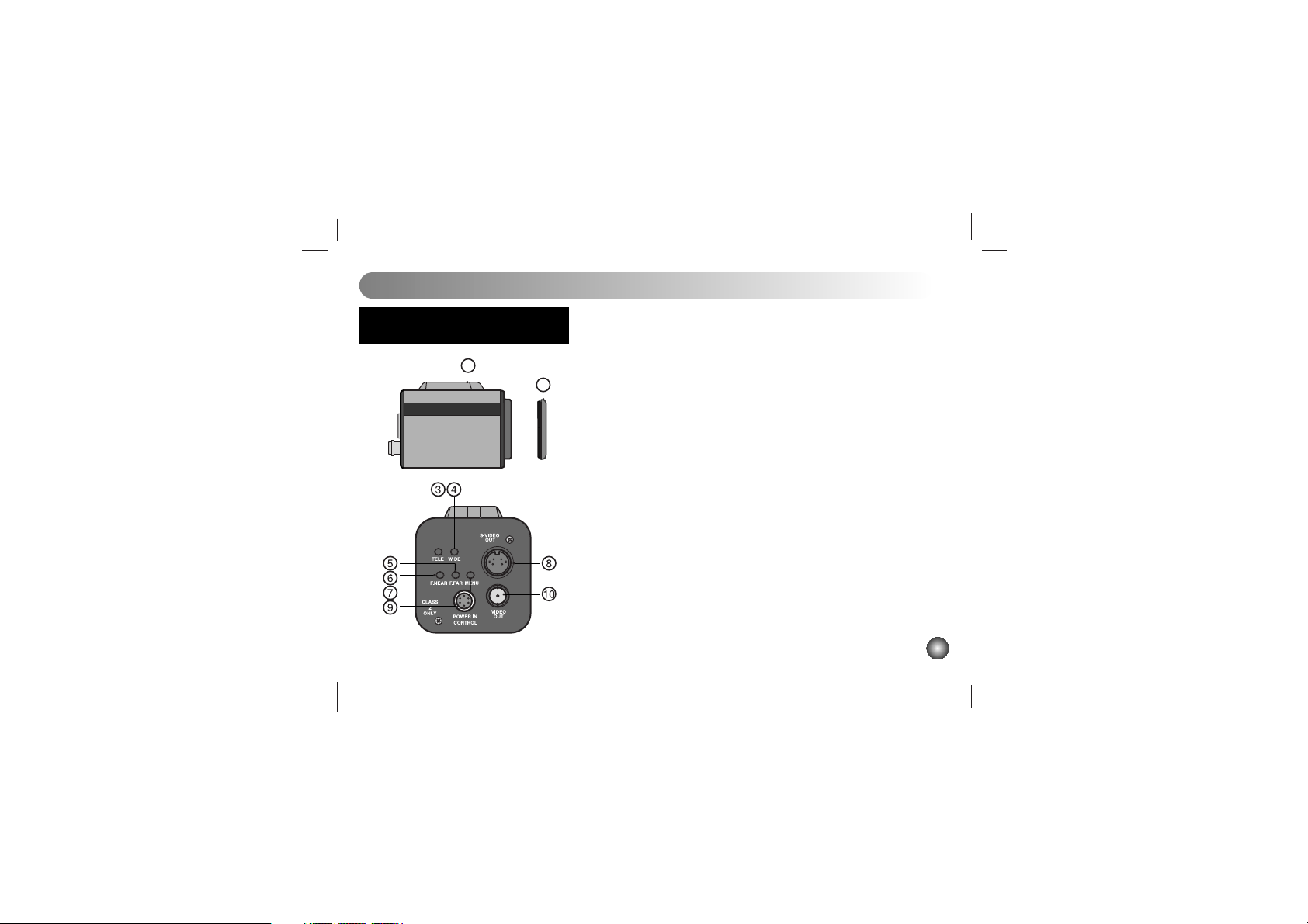
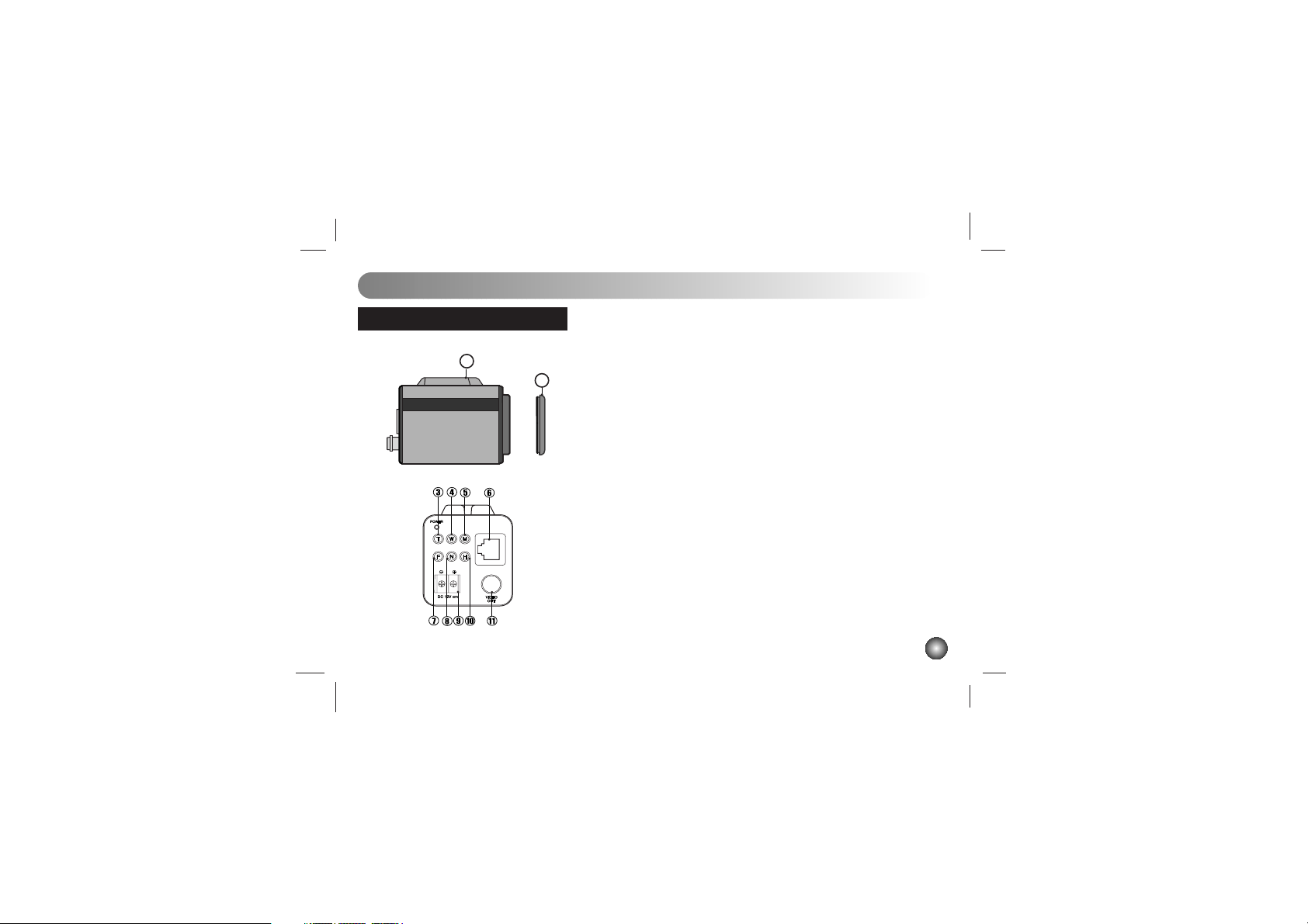
Operating Controls and Their Functions
5
1. Tripod adapter
This adapter can also be attached on the bottom of the camera.
2. Lens mount cap
3. TELE Key
When push the TELE KEY, picture is telephoto
4. WIDE Key
When push the WIDE KEY, picture is wide angle
5. Focus Near Key
In a manual situation, focus get near.
6. Focus Far Key
In a manual situation, focus get far.
7. Menu Key
If you want to set up a diverse function, you can push this button.
8. Video output (S-Video type)
Connect to the S-Video in connector of a monitor.
9.
Interface of camera control JACK (6 Pin Din Jack Type)
• Connect to an external voltage controller
• You can supply a camera with power from this. (DC12V)
10. Video output (BNC type)
Connect to the video in connector of a monitor.
1
Model: LVC-C500, LVC-C503,
LVC-C510, LVC-C513
2
6
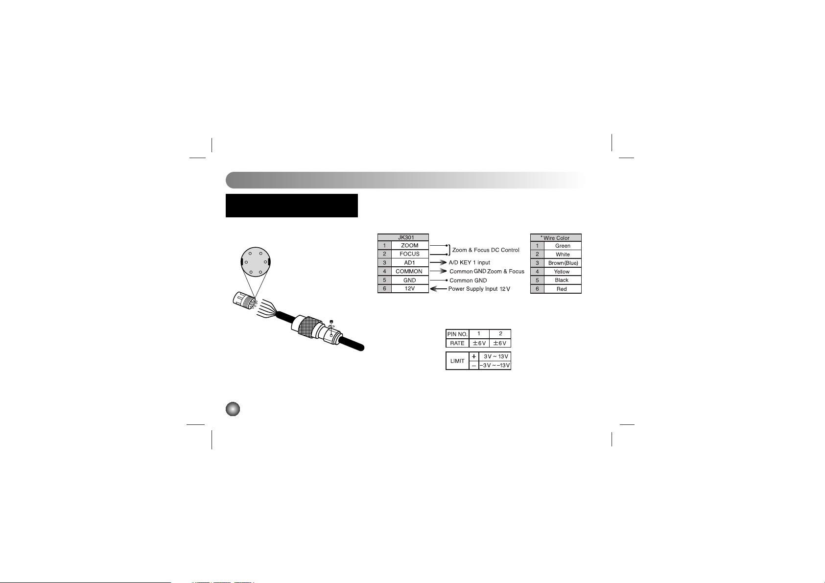
Power In / Control
You can adjust focus and zoom by a pin terminal on the back side
of the camera.
1
4
3
5
6
2
*
is the color of the cable. (If it is offered)
Adjust voltage from 1 pin and 2 pin
Model: LVC-C500, LVC-C503,
LVC-C510, LVC-C513

7
Model: LVC-C500, LVC-C503,
LVC-C510, LVC-C513
External Key (A/D IN)
Schematic diagram of wired
remote-control
8
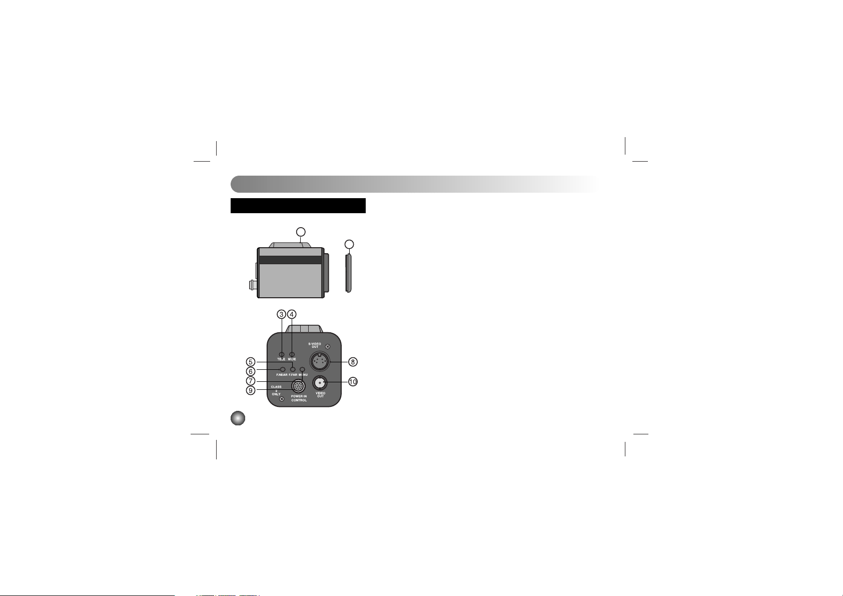
Operating Controls and Their Functions
1. Tripod adapter
This adapter can also be attached on the bottom of the camera.
2. Lens mount cap
3. TELE Key
When push the TELE KEY, picture is telephoto
4. WIDE Key
When push the WIDE KEY, picture is wide angle
5. Focus Near Key
In a manual situation, focus get near.
6. Focus Far Key
In a manual situation, focus get far.
7. Menu Key
If you want to set up a diverse function, you can push this button.
8. Video output (S-Video type)
Connect to the S-Video in connector of a monitor.
9.
Interface of camera control JACK (12 Pin Din Jack Type)
• Connect to an external voltage controller
• You can supply a camera with power from this. (DC12V)
10. Video output(BNC type)
Connect to the video in connector of a monitor.
1
Model: LVC-C530, LVC-C533
2

9
Power In / Control
You can adjust focus and zoom by a pin terminal on the back side
of the camera.
*
is the color of the cable.(If it is offered)
Model: LVC-C530, LVC-C533
10
Power In / Control
Model: LVC-C530, LVC-C533

11
External Key (A/D IN)
Schematic diagram of wired
remote-control
Model: LVC-C530, LVC-C533
12
Model: LVC-C553
Operating Controls and Their Functions
1. Tripod adapter
This adapter can also be attached on the bottom of the camera.
2. Lens mount cap
3. TELE Key
When push the TELE KEY, picture is telephoto
4. WIDE Key
When push the WIDE KEY, picture is wide angle
5. Menu Key
If you want to set up a diverse function, you can push this button.
6.
Control JACK (RJ45)
Connect RS-422 interface
7. Focus Far Key
In a manual situation, focus get far.
8. Focus Near Key
In a manual situation, focus get near.
9. DC 12V screw terminal
Connect to an external power supply of DC 12V.
10. Hot Key
Use to day & night switching get mode.
11. Video output(BNC type)
Connect to the video in connector of a monitor.
1
2
13
Model: LVC-C553
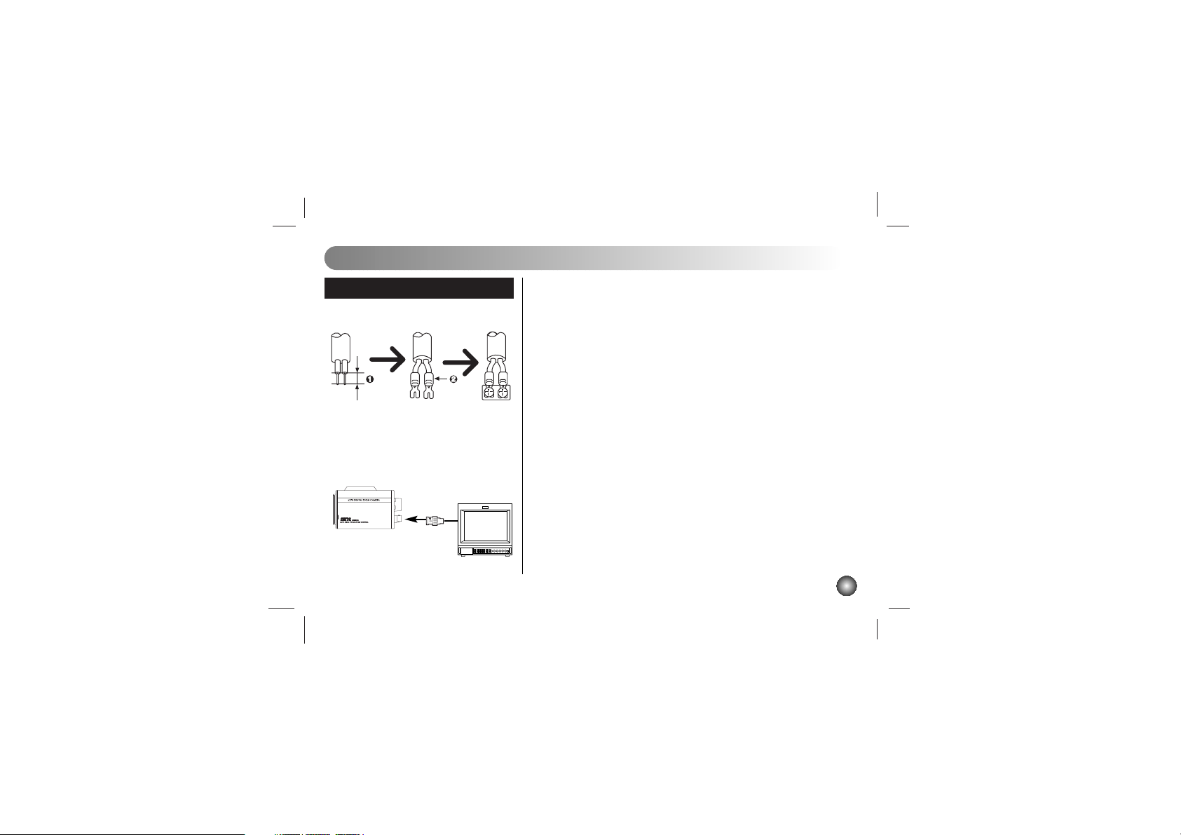
Connections
Power Connection
1. Remove the insulation on the power cable as illustrated.
2. Attach the terminal tips.
3. Connect to the 12V DC UL Listed, Class 2 Power
Supply only on the camera.
Connection the monitor
1. To VIDEO OUT
2. To Video input on the monitor
123
1 2
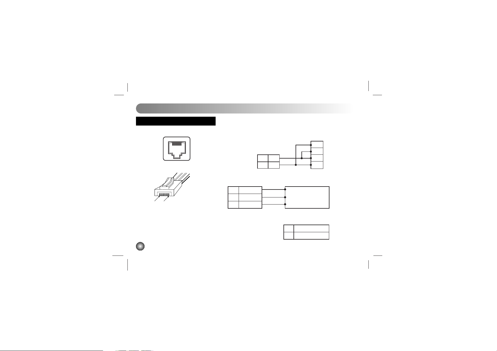
14
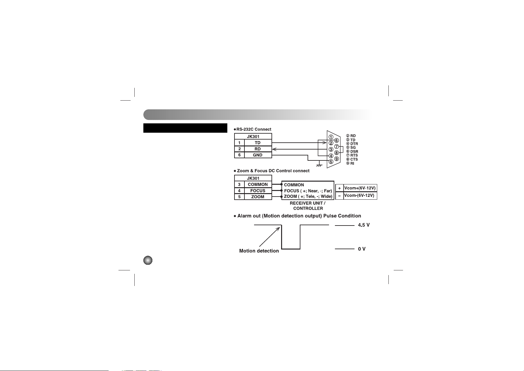
Control
Remote Control Lines are connected to RJ-45 socket as
shown below.
In case of Zoom/Focus DC control Interface(option)
Voltage Range
7T-
8T+
T+
T-
R-
R+
CONTROL OUT Controller
PIN 8 PIN 1
CONTROL
In case of RS-485 INTERFACE (Basic)
4 ZOOM
5 COMMON
6 FOCUS
ZOOM(+Tele, -Wide)
COM
FOCUS(+Near, -Far)
Receiver/Controller
+ Vcom + (+5~15V)
- Vcom - (+5~15V)
Model: LVC-C553

15
MENU DESCRIPTIONS
Using TELE, WIDE, F. NEAR, F. FAR button
• TELE and WIDE are used for UP and DOWN.
• FOCUS+ and FOCUS- are used for INCREASE and DECREASE the data.

16
CAMERA ID
1. CAMERA ID
To connect a large number of camera , It can be
assigned to identification number to each camera for
camera control easily.
(OFF, 0 - 255: total numbers of ID are 256)
• It only can be set this function using ID commend.
To transfer ID Code of camera , In first byte at PC control.
Set the ID number of camera , and then the ID number
display continuously.
17
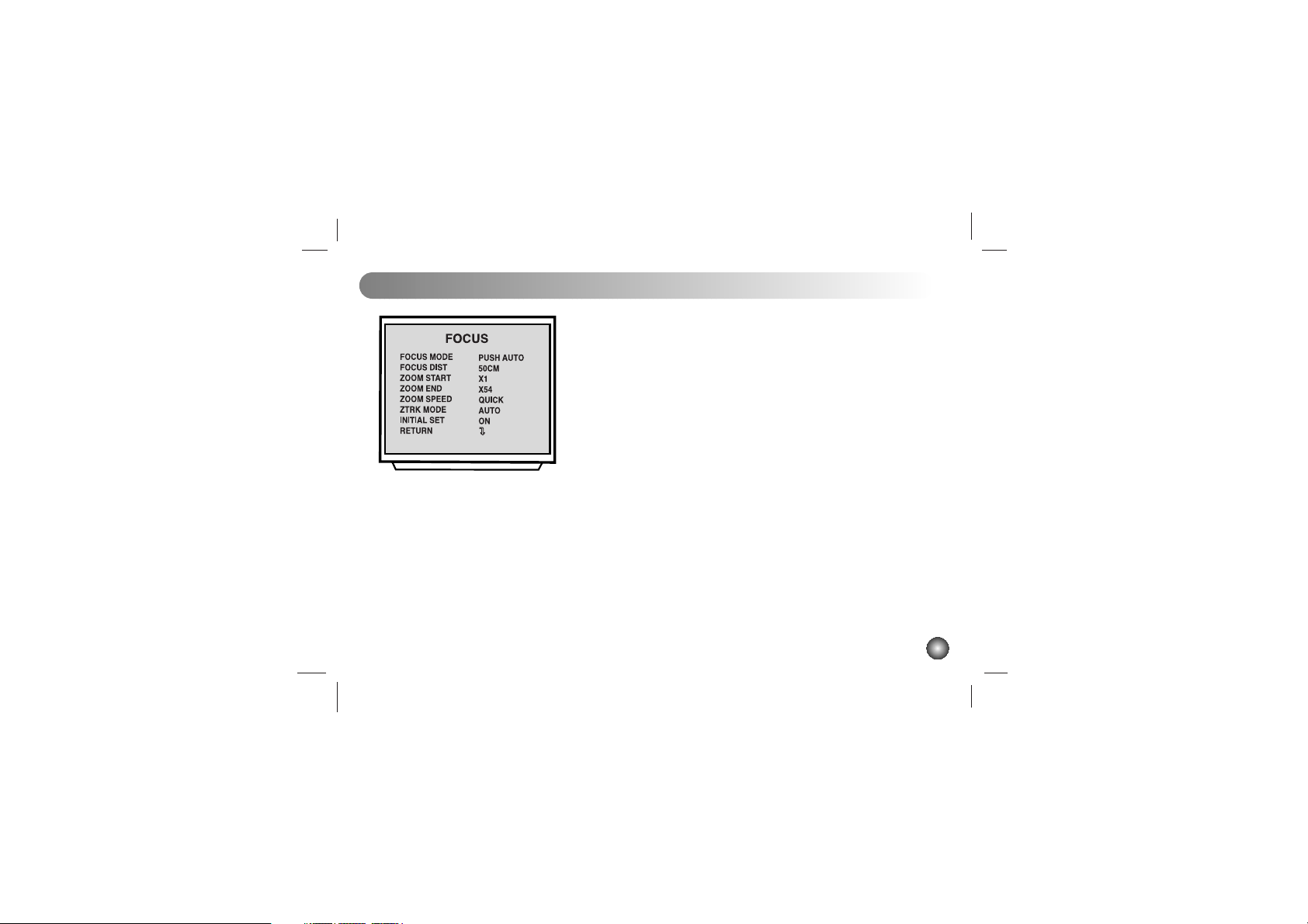
2. Focus Set:
2-1. Focus Mode Set
This function is for focus mode setting
A) Set up “FOCUS SET” in main menu using Tele/Wide key.
Select the “FOCUS MODE” in submenu using Tele/Wide
key. And then set the mode (Auto, Push auto, or Manual)
using Focus key.
2-2. Focus Distance Set
This function is for selection of minimum shooting
distance.
A) Select the “FOCUS DIST” in submenu using Tele/Wide key.
B) Set the focus distance mode from 1cm to 5M. (1cm, 10cm,
50cm, 1M, 3M, 5M) using Focus key.
2-3. ZOOM START Set
This function is for selection of zoom start position.
A) Select the “ZOOM START” in submenu using Tele/Wide
key.
B) Set the Zoom start mode from x1 to x26 using Focus key.
FOCUS MODE SET
FOCUS MODE SET
18
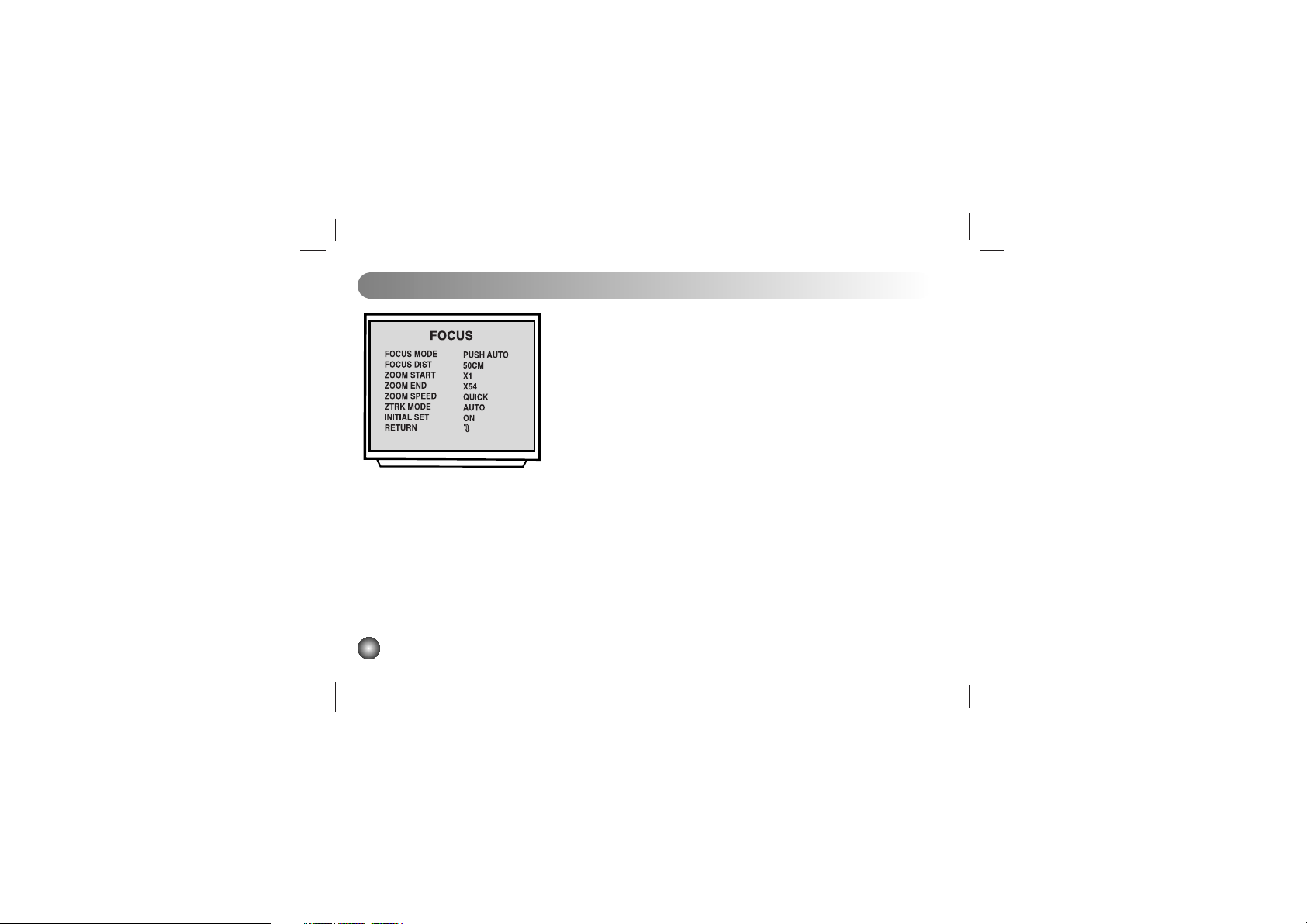
2-4. ZOOM END Set
This function is for selection of zoom end position.
A) Select the “ZOOM END” in submenu using Tele/Wide key.
B) Set the Zoom end mode using Focus key.
LVC-C503/C513/C533/C553: from (Zoom Start + 1) to X54
LVC-C500/C510: from (Zoom Start + 1) to X324
2-5. ZOOM SPEED Set
This function is for selection of zoom speed.
A) Select the “ZOOM SPEED” in submenu using Tele/Wide key.
B) Set the Zoom speed, Slow, Middle , Quick using Focus key.
2-6. ZOOM TRACKING MODE Set
This function is for selection of zoom tracking mode.
A) Select the “ZTRK” in submenu using Tele/Wide Command,
B) Set the Zoom tracking mode to Auto or Manual.
* Zoom tracking means focused zooming state.
19
FOCUS MODE SET
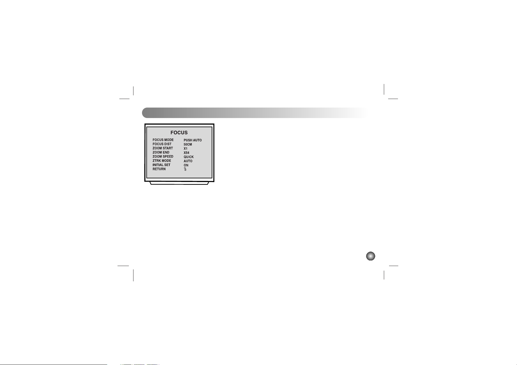
2-7. INITIAL SET
If initial mode set to ON, All FOCUS SET function is
changed to the factory setting.
A) Select the “INITIAL SET” in submenu using Tele/Wide key.
B) Set the initial set mode to ON or OFF using Focus key.
2-8. RETURN TO MAIN MENU
This function is exit to main menu.
A) Select the “RETURN” in submenu using Tele/Wide key.
B) Set the return mode using Focus key.
3. AWB SET
3-1. WB Mode Set
This function is for changing the WB mode.
A) Set up “AWB SET” in main menu using Tele/Wide key.
B) Select the “WB MODE” in submenu using Tele/Wide key.
C) Set the mode Auto, Push auto , Manual, Outdoor, Indoor using
Focus key.
*WBC MODE: Use for changing White Balance Mode .
1) AUTO: WB Range 2500°K ~ 9500°K .
2) PUSH AUTO: Set the AWB mode to Push Auto, then WB Mode
is auto.
3-2. RED ADJUST Set
This function is available for Manual WB mode.
This mode is the adjustment of user option for special color.
A)
Select the “RED ADJUST” in submenu using Tele/Wide key.
B) Adjust the level from (0-255 MANUAL) using Focus key.
AWB SET (Auto White Balance)
20
AWB
WBC MODE
RED ADJUST
BLUE ADJUST
INITIAL SET
RETURN
AUTO
NOT USE
NOT USE
ON

AWB SET (Auto White Balance)
21
3-3. BLUE ADJUST Set
This function is available for Manual WB mode.
This mode is the adjustment of user option for special
color.
A) Select the “BLUE ADJUST” in submenu using Tele/Wide key.
B) Adjust the level from (0-255 MANUAL) using Focus key.
3-4. PUSH AUTO
In case of PUSH AUTO WB mode.
Adjust the push auto mode ON, WB act automatically.
3-5. INITIAL SET
If initial mode set to ON, All AWB function is changed
to the factory setting
A) Select the “INITIAL SET” in submenu using Tele/Wide key.
B) Set the initial set mode to ON or OFF using Focus key.
3-6. RETURN TO MAIN MENU
This function is exit to main menu.
A) Select the “RETURN “ in submenu. Using Tele/Wide key.
B) Set the return mode using Focus key.
AWB
WBC MODE
RED ADJUST
BLUE ADJUST
INITIAL SET
RETURN
AUTO
NOT USE
NOT USE
ON

4. AE SET
4-1. AE Mode Set
This function is for changing to AE mode.
A) Set up “AE SET” in main menu using Tele/Wide key.
B) Select the “AE MODE” in submenu using Tele/Wide key.
C) Set the mode auto, IRIS MAN, SLOW MAN, SHUTTER MAN,
Auto using Focus key
Note: SLOW MAN option is not available for LVC-C500,
LVC-C510, and LVC-C530.
4-2. IRIS ADJUST Set
This function is available for IRIS MAN mode.
A)
Select the “IRIS ADJUST” in submenu using Tele/Wide key.
B) Adjust the level from 0 to 255 using Focus key.
4-3. AGC ADJUST Set
This function is available for SLOW MAN mode /
SHUTTER MAN mode .
A) Select the “IRIS ADJUST” in submenu using Tele/Wide key.
B) Adjust the level from 0 to 7 using Focus key.
AE SET (Auto Exposure)
22
 Loading...