

Page 1
● HQ (High Quality) picture
enhancement system
● Full function infra-red remote
control handset
● Programmable 88 channel memory
with Frequency synthesised tuner
● ACMS (Automatic Channel Memory
System) plus - the channels will be
preset, sorted and memorized
automatically.
Hi-Fi-Stereo-
Video recorder
Owner’s manual
● 7 event/1 month programmable
timer
● Built-in ShowView programming
● Recording and playback for 16:9
Wide-screen format
● Energy Saving function
● ICON O.S.D (On Screen Display) -
Enables menu to display on the
blue picture and actual picture.
● NTSC playback on PAL TV
● PREMIERE Compatible
● LP - Long Play - recording and
playback
● Logic & Picture Search
● Lock
● Auto Power on and Play
● Fine still, Frame advance & Slow
functions
● Real Time Counter
● Quick Start function
● Auto Tracking System
● Reception of Stereo, Bilingual &
Mono sound
● Hi-Fi Audio System
● Simulcast Recording
LV4787
LV4981
LV4767
LV4765
LV4747
LV4745
Model No. GC987P1/GC981P1/GC967P1/GC961P1/GC947P1/GC941P1
Part No. MFL46896863
Page 2
Thank you for buying this LG video cassette recorder Model
LV4787/LV4981/LV4767/LV4765/LV4747/LV4745.
Before using your video recorder you need to be familiar with the names of some of the
buttons on the remote control handset (see OPERATING THE VIDEO RECORDER,
pages 4 to 6), and you need to set up the video recorder so that it can receive the TV
stations in your area and so that your TV set can receive pictures from it (see p 12 to 14).
Installation
POWER
This Video Recorder operates on a mains supply of 200-240V~, 50 Hz.
SERVICE
Never remove the cover of the video recorder. There are no user serviceable parts
inside. If it does not operate properly, unplug it and contact your dealer.
PRECAUTIONS
For safe operation and satisfactory performance of your video recorder, keep the
following in mind when selecting a place for its installation.
● Shield it from direct sunlight and keep it away from sources of intense heat.
● Avoid dusty or humid places.
● Install the video recorder in a horizontal position only.
● Avoid locations subject to strong vibration.
● Do not place the video recorder near strong magnetic fields.
● Do not move the video recorder from a cold to a hot location or vice versa.
MOISTURE CONDENSATION
Under special conditions like moving your video recorder from a cold to a warm room,
moisture condensation can build up on the head drum, one of the most crucial parts of
the video recorder. In order to prevent in such case any damage to your video
recorder HEAD DRUM, connect the video recorder power cord to the AC line, press
the “ ” button on and allow at least 2 hours for the video recorder to dry out.
CONDENSATION IS LIKELY TO OCCUR WHEN:
The video recorder is moved from a cold room to a warm room or from outdoors to
inside your home.
● A cold room is heated quickly.
● The humidity is very high.
Welcome to LG
2
This product is manufactured to comply with EMC Directive
2004/108/EC Low Voltage Directive and 2006/95/EC.
European representative :
LG Electronics Service Europe B.V.
Veluwezoom 15, 1327 AE Almere, The Netherlands
(Tel : +31–036–547–8940)
The apparatus shall not be exposed to dripping or splashing and that no objects
filled with liquids, such as vases, shall be placed on the apparatus.
Page 3
Operating the video recorder 4-6
The remote control handset 4-5
The front & back of the video recorder 6
Installing your video recorder 7-9
Setting the VCR output channel 10
On screen displays 11
Storing TV stations 12-16
Automatic tuning 12
Manual tuning 13-14
Moving the programme order of the “TV station table” menu 15
Clearing stations from the “TV station table” menu 16
Time and date setting 17
Using the VCR to play back a tape 18-19
Loading & Unloading a video cassette 18
Types of video cassette 18
How to using the Energy saving mode 18
Normal playback 19
Still picture playback 19
CM (Commercial Message) Skip 19
Other playback features 20-22
Fast forward, Rewind 20
Logic & picture search 20
OPR (Optimum Picture Response) 20
Slow motion playback, Shuttle 21
Selection of the colour system 22
Recording with decoder 22
Using the video recorder to record 23-24
To record 23-24
Immediate timer (ITR) 24
Programming the video recorder timer 25-29
Introduction to ShowView 25
ShowView programming on the TV screen 25-26
Recorder timer programming using the on screen displays 27-28
Checking & clearing stored timer programmes 29
Overlapping timer programmes 29
Other features 30-33
Introduction 30
Digital tape counter, Remaining tape volume, Memory stop 31
Tracking controls 32
Automatic playback, memory power shut-off 32
The child lock, 16:9 Compatibility, Self-Diagnosis 33
The Hi-Fi stereo sound system 34
Recording from another equipment 35
ez (easy) operations 36
Controlling the TV 37
Specifications 38
Before calling for service . . . 39
Contents
3
Page 4
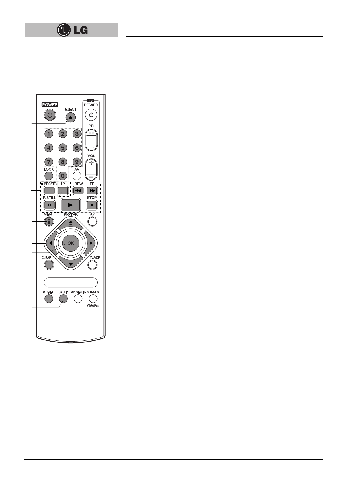
The Remote Control Handset
This video recorder is designed so that almost all of its functions can be controlled
from the REMOTE CONTROL HANDSET. This must have a “line of sight” to the
sensor on the front of the video recorder. It must be within an angle of 30 degrees
either side of the centre. The maximum operating distance is about 7.5m (25 feet).
Some functions can also be controlled with the controls on the FRONT PANEL of the
video recorder.
1
POWER
To switch the video recorder on and off.
2
EJECT
To eject a tape (see p 18).
3
NUMBER BUTTONS:
To select programme channels. To programme numeric information into On
screen displays.
4
LOCK
To turn the LOCK function on/off (see p 33).
5
Basic operation buttons;
● P/STILL (see p 19, 23).
● REWIND/REVIEW (see p 20).
● PLAY (see p 19).
● FAST FORWARD/CUE (see p 20).
● STOP (see p 19).
● REC/ITR (see p 23 to 24).
6
TAPE SPEED SELECT (LP)
To select the recording speed of the tape (see p 23).
7
i (MENU)
To display the on screen display (OSD) menu (see p 11).
8
CURSORS (D, E, F, G)/PR(+/-)/TRK(+/-)
DE:
● During OSD menu, for moving the cursor, selection bar up or down.
● Switches one channel programme up or down.
● During playback, tracking control.
● During still playback, adjusting vertical tremble.
● To adjust manual fine tune for receiving normal audio and picture (see p 13).
FG:
● During OSD menu, for moving the cursor to the left or right.
● Adjust the playback speed (see p 21).
● To clear a data (see p 29).
9
OK
● Confirms menu selection (see p 11).
● Calls the on screen display (see p 31).
● To switch the display on the TV screen between the current time, the tape
counter (in hours and minutes) and the remaining tape volume
(see p 31).
This function will only operate when a tape is loaded.
10
CLEAR
To reset the tape counter to zero (see p 31).
11
ez REPEAT
(see p 36).
12
CM SKIP
To fast forward picture search through 30 seconds of recording (see p 19).
Operating the video recorder
4
1
2
3
4
5
6
7
8
9
10
11
12
Page 5
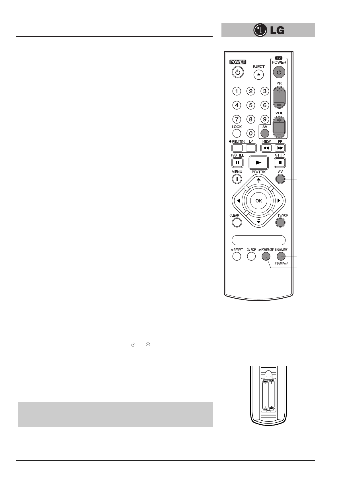
13
TV Control Buttons (see p 37)
TV POWER: Turns on or off the TV.
TV PR +/–: Selects TV’s channel.
TV VOL +/–: Adjusts TV’s volume.
TV AV: Selects the TV’s source.
14
AV
Select input source for recording into tape (see p 23, 37).
15
TV/VCR
Set this button to;
● VCR: To monitor, view playback or view the video recorder’s tuner.
● TV: To watch TV or view another programme while recording one
programme (see p 24).
16
SHOWVIEW (LV4787/LV4767/LV4747)
To display the programme menu for ShowView programming on the handset (see p
25 to 26).
17
ez POWER OFF
(see p 36).
How to install batteries
The wireless remote control is powered by two “AAA” size batteries.
1
Remove the battery compartment lid.
(Lift it up while pressing the tap forward.)
2
Load the new batteries with their polarities ( ) aligned properly and replace
the lid.
Operating the video recorder
5
●
Do not use an old and a new battery together, and never use an alkaline battery
with a manganese battery.
●
If you do not intend to use the remote control unit for a long period of time,
remove the batteries and store them in a cool, dry place.
13
14
and
15
16
17
AAA
AAA
Page 6
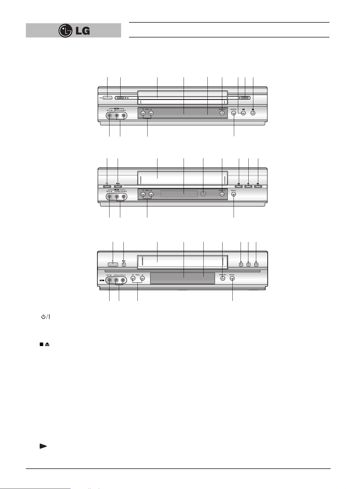
Operating the video recorder
6
1
To switch the video recorder on and off.
(see p. 18).
2
To stop the tape, or eject it from the video recorder (see p 18).
3
VIDEO CASSETTE COMPARTMENT
When a cassette is inserted loading is completed
automatically.
4
MULTI FUNCTION DISPLAY
5
REMOTE CONTROL SENSOR
To receive the signals from the remote control handset.
6
REC/ITR
Used to record and set the ITR (Instant Timer Recording)
time (see p 23 to 24).
7
REWIND
8
To play the tape (see p 19).
9
FF
10
P/STILL
Switches to still picture (see p 19), during recording to
pause (see p 23).
11
PROG. (▼/▲)
Allows you to scan through memorized channels.
12
AUDIO INPUT TERMINALS (L/R)
To record audio from an external audio source (see p 8).
13
VIDEO INPUT TERMINAL
To receive a signal from another video equipment (e.g.
Camcorder) (see p 9).
The front of the Video Recorder
1
2
3
4 5
6
78 9
10
12
1113
1
2
3
4 5
6
789
10
12 11
13
LV4747/LV4745
3
/I
1
2
3
4 5
6
789
10
12 12
13
LV4767/LV4765
LV4787/LV4981
/
Page 7
Installing your video recorder
7
IMPORTANT!
The guidance given on the next three pages in the most common forms of
connection. However please check with your manufacturers instruction books for
specific information. Make sure all connections are made with both your VCR and
additional appliance unplugged from the mains to avoid damaging your equipment.
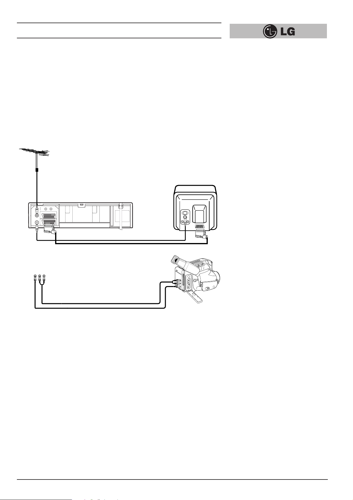
Connecting a VCR using a SCART leads is one of the best ways to achieve optimum
sound and picture quality from video-tape playback. If you own a stereo TV you will
be able to enjoy stereo sound when playing a stereo video tape; you will be unable to
enjoy this facility if you connected just a normal aerial lead.
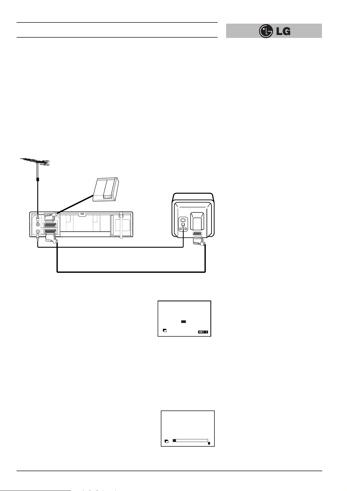
Connecting to a TV & DECODER
Aerial (NOT SUPPLIED)
The quality of the sound and picture can be greatly
influenced by the positioning, quality and state of
repair of your external aerial.
Television (NOT SUPPLIED)
Rear view of your VCR
Decoder (
NOT SUPPLIED)
All connections
must be made with
both your VCR and
Television
unplugged from the
mains
INITIAL PRESET
For the following steps we do assume that you have just
connected your video recorder for the very first time. In this
case the video recorder is on after mains
connection. You should not touch any buttons yet. On the
connected TV you will now see.
Note - If this menu does not appear, your video recorder
was programmed already.
1
Select the desired country with cursor “F” and “G” buttons.
“A”: Austria, “B”: Belgium, “CH”: Switzerland,
“D”: Deutsch, “DK”: Denmark, “E”: Spain, “F”: France, “I”: Italy,
“N”: Norway, “NL”: Netherlands, “P”: Portugal, “S”: Sweden,
“SF”: Finland.
2
Press the “OK” button to start the automatic storing of
the channels of the TV stations in your area.
Aerial Connection Cable
(
75 Ohms) (SUPPLIED)
Do not try and force the connector into
place, it should plug in easily.
SCART Lead
• If you use a SCART lead picture quality will be improved and
you will be able to enjoy stereo sound when playing tapes.
G
SORTIE
D
AUDIO
OUT
L
EURO AV2 DECODER
EURO AV1 AUDIO/VIDEO
R
ENTREE
ANTENNE
AERIAL
SORTIE
ANTENNE
RF.OUT
A
B D DK E F I
CH
NNL PSSF
Pr-12
ACMS
ANDERE
OK
i
ACMS
01
s
Pr-12
C03 00 ARD
E
i
Page 8
Installing your video recorder
8
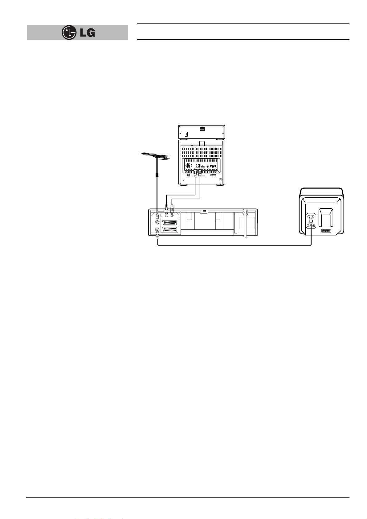
Connecting to your Hi-Fi (Audio Out)
Audio out sockets & Phono
Leads
The phono sockets for connecting your
VCR to your Hi-Fi are on the back of the
set; L = Left sound output, R = Right
sound output. You normally have to
select the AUX function on your Hi-Fi.
Please note if you press the MUTE
button on your TV only the sound from
the TV’s speaker is switched off, not
your Hi-Fi.
Hi-Fi (NOT SUPPLIED
)
An audio system can be connected to the AUDIO OUT sockets on the back of your
VCR.
Please remember to turn the volume to minimum on your Hi-Fi, then gradually
increase the volume; this will prevent damaging your speakers and save your ears
from an extremely noisy shock!
FM
AM
FM
G
SORTIE
D
AUDIO
OUT
L
EURO AV2 DECODER
EURO AV1 AUDIO/VIDEO
R
ENTREE
ANTENNE
AERIAL
SORTIE
ANTENNE
RF.OUT
RL
Page 9
Installing your video recorder
9
Camcorder Connection
Make sure all connections are made with both your VCR and Camcorder unplugged
from the mains to avoid damaging your equipment. To make connecting your
Camcorder easier we have designed the Audio IN (Left and Right) and Video IN
sockets on the front panel of your VCR.
You may also use the SCART socket on the rear of your VCR as well.
Back view of your VCR
Whichever socket you choose to use remember to select the appropriate recording input e.g.
SC, AV1, AV2 or AV3.
If you are using the sockets on the front panel select source AV3.
Front view of your VCR
Camcorder (NOT SUPPLIED)
Audio Left & Right Lead
Video Lead
VIDEO IN L(MONO)-AUDIO IN-R
G
SORTIE
D
AUDIO
OUT
L
EURO AV2 DECODER
EURO AV1 AUDIO/VIDEO
R
ENTREE
ANTENNE
AERIAL
SORTIE
ANTENNE
RF.OUT
VIDEO IN L- AUDIO IN -R
To AUDIO OUT
(L/R)
To VIDEO OUT
Page 10

Setting the VCR output channel
10
Your TV set receives the video recorder signal like another TV station. So you have to
select a programme number for the video recorder.
Take care to select this programme number, whenever you control the video recorder,
or watch a recording. Only if you have selected this programme number, which we
call video programme number, you will see the picture from the video recorder on the
screen.
If you connect a monitor or a TV set equipped with audio and video terminals, this
adjustment will not necessary. Consult the operating instructions of your TV set.
Connect the video recorder as described in the section on Connections (see on
previous page).
Setting the output channel of the VCR
SETTING THE VIDEO CHANNEL WITH
PLAYBACK
The output channel of the video recorder is set at UHF channel 36.
1 Turn on the TV set and the video recorder.
2 Play any video cassette tape on your video recorder.
3 Select the correct channel (36) on your TV set.
And then you will see the picture being played in video recorder.
(Note - You will need to look at the instruction manual for your TV set if you do
not know how to do this.)
SETTING THE VIDEO CHANNEL WITH
OSD (ON SCREEN DISPLAY)
1 Turn on the TV set and the video recorder.
2 Repeat above No. 3. And then you will see a blue background picture on the TV
screen.
3 Store this channel in an unused programme number on your TV set.
Changing the transmitter channel
If the channel 36 is already occupied at your TV set, or if the picture is distorted, you
can change the transmitter channel of the video recorder.
1 Select an unoccupied channel between 22 and 68 on your TV set.
2 During power off mode (only clock display) press the PROG. “▼” or “▲” buttons
on the VCR for more than 4 seconds.
Then, “RF36” will be displayed on the VCR’s display.
3 Press the PROG. “▼” or “▲” buttons on the VCR to select another video channel
e.g. between channels 22 and 68.
You can also set it to “OFF” if there is any interference when your TV is connected
to the VCR with a SCART lead.
4 Press the “ ” button when you have finished.
1
2
3
Page 11
On Screen Displays
11
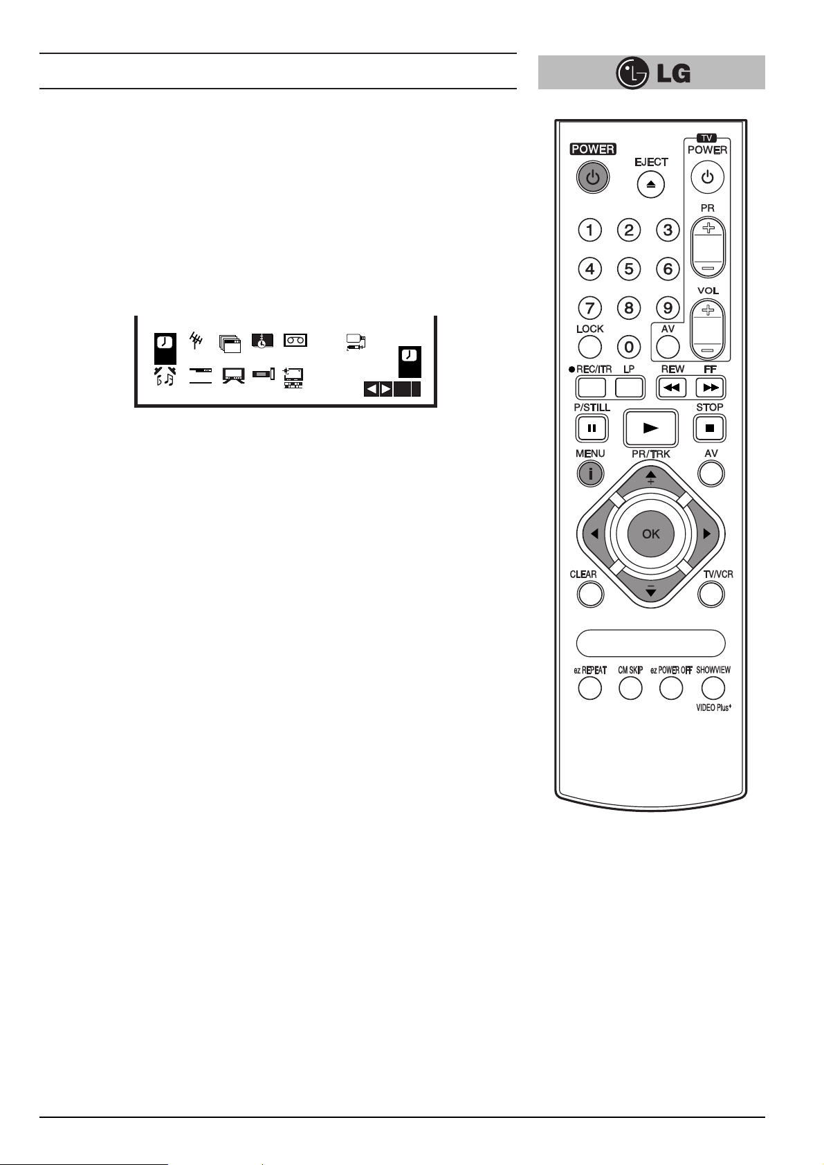
A number of the features of this video recorder can be set and altered using the
handset with On Screen Displays (menus) on the TV screen.
The Main menu
1
Switch on your TV set and video recorder by pressing the “POWER” button.
2 Press the “i” button to display the Main menu.
3 Press the cursor “F” and “G” buttons to select the desired menu and press the
“OK” button.
Note - After using the menus press the “i” button to remove menus from the TV
screen.
REC
Used to record a programme with the timer (see p 27 to 28).
PR SET
Used to view stored TV stations or to set TV station information manually (see p 13 to 14).
ACMS
Used for automatic setting of the TV stations (see p 12).
TIME DATE
To set the clock manually (see p 17).
SYSTEM (AUTO →→PAL
→→
MESECAM)
Select the colour system used for playback and recording (see p 22).
ABC OSD
Allows you to select the language of the On Screen Display. You can select between
ENGLISH, DEUTSCH, ITALIANO, ESPAÑOL, E^^HNIKA and PORTUGUÊS.
Dr.
To check a problem with your VCR (see p 33).
AUDIO (STEREO, LEFT, RIGHT or MONO)
Used to select the channel for audio output (see p 34).
OSD (On Screen Display)
Switches the on screen display OFF or ON (see p 31).
16:9/4:3
To select the aspect ratio of your TV (see p 33).
● AUTO: for playing back wide-screen programmes as wide, normal programmes as
normal.
● 4:3 : for recording and playback with a normal format.
● 16:9 : for recording and playback with a 16:9 Wide-screen format recording.
DECODER
To use DECODER scart socket for the connection of a pay-TV decoder (see p 22).
OPR
To improve the playback picture (see p 20).
AB
C
OSD
VCR
Dr.
REC
OK
i
REC
AUDIO
P
SET
R
f
OSD
OSD
ON
OFF
Pr-12
ACMS
16:9
4:3
12
TIME
DATE
+
-
DECO-
DER
SYS-
TEM
OPR
Page 12
Storing TV stations
12
Up to 88 TV stations (88 channels) can be stored in the memory of this video
recorder. These can be set automatically or manually.
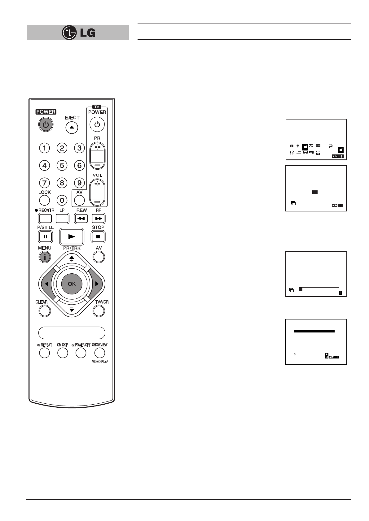
Automatic tuning
To carry out Automatic tuning:
1
Turn on the TV and the video recorder
(with the “POWER” button).
2
Press the “i” button and select “ACMS ” by using the
cursor “
F” and “G” buttons.
3
Press the “OK” button.
4
Select the desired country with cursor
“
F” and “G” buttons.
“A”: Austria, “B”: Belgium, “CH”: Switzerland,
“D”: Deutsch, “DK”: Denmark,
“E”: Spain, “F”: France, “I”: Italy,
“N”: Norway, “NL”: Netherlands,
“P”: Portugal, “S”: Sweden, “SF”: Finland, Others.
5
Press the “OK” button to start the automatic storing
of the channels of the TV stations in your area.
The VCR’s clock will be set automatically when
automatic tuning has finished (LV4787/LV4767/
LV4747).
If the clock is wrong please see “Setting the video
recorder’s clock manually” on page 17.
6
After finishing the storing, the video
recorder will sort the stations.
Automatic channel tuning has been
completed when the “TV station table”
menu appears on the TV screen.
7
Press the “i” button to remove the
menus from the TV screen.
12
Pr-12
P
REC
R
f
ON
AUDIO
OFF
A
NNL PSSF
Pr-12
ACMS
01
s
Pr-12
ACMS
01 C03 00 ARD
02 C02 00 ZDF
03
04
05 C02 00 HR3
06 - - - - - - - - 07
08 - - - - - - -
P
SET
R
SYS-
TIME
SET
ACMS
TEM
DATE
+
-
OSD
OSD
16:9
DECO-
4:3
OPR
DER
B D DK E F I
CH
C03 00 ARD
00 WDR3
S40
00
S11
- - - -
- -
MOVE:
DELETE:
AB
C
OSD
OTHERS
BR3
- - - - -
VCR
Dr.
Pr-12
ACMS
OK
i
OK
i
E
i
OK,i
Page 13

Storing TV stations
13
Manual tuning
TV station Channel numbers and Station names can be
stored manually.
1
Press the “i” button on the video recorder handset.
The menu will appear on the TV screen.
2
Use the cursor “F” and “G” buttons to select “PR SET”
3
Press the “OK” button to enter the manual tuning
mode.
4
Press the “AV” button to select the type of TV
channels.
● “C” for standard channels C02-C69.
● “S” for special channels (Cable) S01-S41.
5
Enter the channel number that you wish to enter the
station with number buttons or cursor “
D” or “E”
buttons.
6
Use “G” button to select “MFT” and control the fine
tuning of the station by pressing the cursor “
D” and
“
E” buttons.
7
Use “G” button to select “STATION”.
REC
AUDIO
REC
AUDIO
Pr-12
P
SET
ACMS
R
f
OSD
OSD
ON
16:9
OFF
4:3
Pr-12
P
SET
ACMS
R
f
OSD
OSD
ON
16:9
OFF
4:3
TIME
DATE
+
DECO-
DER
12
TIME
DATE
+
DECO-
DER
C
SYS-
OSD
Dr.
TEM
-
OPR
SYS-
TEM
-
OPR
AB
OSD
REC
OK
i
VCR
C
Dr.
P
SET
R
OK
i
VCR
12
AB
PR01CH MFT STATION
C- -
P
SET
R
PR
01 00
P
SET
R
PR01CH MFT STATION
P
SET
R
PR01CH MFT STATION
P
SET
R
-- -----
CHANNEL/CABLE:AV
CH MFT STATION
S01
CHANNEL/CABLE:AV
S27
00
CHANNEL/CABLE:AV
S27
00
CHANNEL/CABLE : AV
i
i
i
i
PR01CH MFT STATION
S27
P
SET
R
00
OK
i
Page 14

Storing TV stations
14
8
Press the “OK” and select the cursor “D” and “E”
buttons to select the station name from list.
NOTE:
Press the use “
G” button to input the station name
manually.
1) Enter the first letter of the station name by
repeatedly pressing the cursor “
D” and “E ”
buttons.
2) Now move the cursor with the “
G” to the next
position and write in the next letter of the station
name.
For corrections move back and forth with the
“
F” and “G” buttons.
3) When you have the station name as required
press the “OK” button and “i” button.
9
Press the “OK” button to select it.
10
Press the “i” button.
The “TV station table” menu will be displayed.
11
End the station storing by pressing the “i” button.
Selecting stored TV stations
Stored TV stations can be selected in either of two ways.
1
Use the “D” and “E” buttons to move from one
station to another.
2
Enter the programme number with the number
buttons, to select a station directly. You can enter
the stations 1 to 9 with the one digit only. The
channel will be selected at once.
When the channel is changed, a screen display (of
a seconds duration) gives the programme number,
and if the broadcast is STEREO or BIL (Bilingual).
ARD
ZDF
WDR 3
BR3
PR01CH MFT STATION
S27 00
P
SET
R
PR01CH MFT STATION
S27 00
P
SET
R
HR3
N 3
NDR3
SWF3
STATION
ARD
OK
i
OK
i
PR01CH MFT STATION
S27 00
P
SET
R
01 S27 ARD00
02 - - - - - - - - 03 - - - - - - - - 04 - - - - - - - - 05 - - - - - - - - 06 - - - - - - - - 07 - - - - - - - - 08 - - - - - - - - -
P
SET
R
MOVE:
DELETE: ,
ARD
OK
i
OK
i
Page 15

Storing TV stations
15
Moving the programme order of the “TV
station table” menu
If you want to move the order of the TV stations you can
easily do so as follows:
1
Press the “i” button on the remote control handset.
The menu will appear on the TV screen.
2
Select “PR SET” with the cursor “F” and “G” buttons
and press the “OK” button.
3
Press the “i” button.
The “TV station table” menu will be displayed.
4
Move the cursor down or up with the cursor “D” and
“
E” buttons to select the programme that you want to
move to another position in the menu (for example
“Pr 03”). Now you press the “
G” button to select
move.
5
Move the cursor to place the cursor line at the
position where to insert the selected programme
(example Pr 04).
6
Press the “OK” button.
The selected station will be moved to the new
programme number.
7
Move other stations, if you wish, by repeating steps 4
to 6.
8
Press the “i” button to remove the menus from the TV
screen.
PR
CH MFT STATION
C03
01 00 ARD
P
SET
CHANNEL/CABLE:AV
R
01 C03 00 ARD
02 C02 00 ZDF
03 S11 00 WDR 3
04 S40
05 C02 00 HR3
06 - - - - - - - - 07
08 - - - - - - -
P
SET
R
- - - -
DELETE:
00
- MOVE:
BR3
- - - - -
i
OK,i
01 C03 00 ARD
02 C02 00 ZDF
03 S11 00 WDR 3
04 S40
05 C02 00 HR3
06 - - - - - - - - 07
08 - - - - - - -
P
SET
R
01 C03 00 ARD
02 C02 00 ZDF
03
S40
S11
04
05 C02 00 HR3
06 - - - - - - - - 07
08 - - - - - - -
P
SET
R
01 C03 00 ARD
02 C02 00 ZDF
03
S40
S11 00 WDR 3
04
05 C02 00 HR3
06 - - - - - - - - 07
08 - - - - - - -
P
SET
R
- - - -
- - - -
- - - -
DELETE:
BR3
00
- - - - -
- -
00 BR3
00
WDR3
- - - - -
- -
00 BR3
- - - - -
- MOVE:
OK
i
OK
i
OK,i
Page 16

Storing TV stations
16
Clearing stations from the “TV station
table” menu
If you want to clear a TV station from the video
recorder’s store you can easily do so as follows:
1
Press the “i” button on the remote control handset.
The menu will appear on the TV screen.
2
Select “PR SET” with the cursor “F” and “G”
buttons and press the “OK” button.
3
Press the “i” button.
The “TV station table” menu will be displayed.
4
Move the cursor down or up with the cursor “D” and
“
E” button to select the programme that you want to
clear. (for example station “Pr - 04”).
5
Press the “F” button to delete. After a short while,
the selected station will be cleared.
6
Clear other stations, if you wish, by repeating steps
4 and 5.
7
Press the “i” button to remove the menus from the
TV screen.
PR
CH MFT STATION
C03
01 00 ARD
P
SET
CHANNEL/CABLE:AV
R
01 C03 00 ARD
02 C02 00 ZDF
03 S11 00 WDR 3
04 S40
05 C02 00 HR3
06 - - - - - - - - 07
08 - - - - - - -
P
SET
R
- - - -
DELETE:
00
- -
MOVE:
BR3
- - - - -
i
OK,i
01 C03 00 ARD
02 C02 00 ZDF
03 S11 00 WDR 3
04 S40 00 BR3
05 C02 00 HR3
06 - - - - - - - - -
- - - -
07
08
P
SET
R
01 C03 00 ARD
02 C02 00 ZDF
03 S11 00 WDR 3
04 S40 00 BR3
05 C02 00 HR3
06 - - - - - - - - 07
08 - - - - - - -
P
SET
R
- - - - -
- - - - - - -
- -
MOVE:
DELETE:
- - - -
- - - - -
- -
PLEASE WAIT
DELETE:
OK,i
OK,i
Page 17

Time and date setting
17
Setting the video recorder’s clock
The clock in this video recorder gives the date (including
the day of the week) and the time. It is set automatically
during Automatic Channel Tuning (LV4787/LV4767/
LV4747). It is also continually checked against the date
and time if this information is being broadcast as it is by all
channels broadcasting a Teletext signal (LV4787/LV4767/
LV4747). It is, therefore, unlikely that you will need to alter
the clock settings.
Whenever the video recorder receives a signal containing
the date and time it adjusts itself to these signals
(LV4787/LV4767/LV4747).
Therefore, the video recorder clock is likely to be always
showing the correct time (LV4787/LV4767/LV4747).
To manually alter the clock:
1
Press the “i” button. The Main menu appears on the
TV screen.
2
Select “TIME DATE” with the cursor “F” and “G”
buttons.
3
Press the “OK” button.
The auto adjust mode can be set to “OFF” by pressing
“
D” and “E” buttons if you want to set the time
manually (LV4787/LV4767/LV4747).
4
Press the “OK” button.
5
Use the number buttons or cursor “D”, “E”, “F” and
“
G” buttons alter the Hours, Minutes, Day, Month and
Year (using the 24 hour clock).
The day of the week will appear automatically when
you have entered the date.
NOTE: Enter 1 as 01, 2 as 02 etc.
• Correct errors during inputting with cursor “F” and
“
G” buttons.
6
Press the “i” button to remove the menus from the TV
screen. The set time will appear on the video
recorder’s Display.
REC
AUDIO
VCR
12
A B
Pr-12
P
SET
R
f
OSD
OSD
ON
OFF
C
SYS-
TIME
ACMS
DATE
+
-
DECO-
16:9
DER
OPR
4:3
12
OSD
Dr.
TEM
TIME
DATE
OK
i
AUTO ADJUST : ON
12
TIME
DATE
HH MM DD MM YY
:..- -
- - - -
- -
12
TIME
DATE
HH MM DD MM YY
:..00 1 01 04 THU
08
12
TIME
DATE
- - - - -
OK
i
i
i
Page 18

Using the VCR to play back a tape
18
NOTE - Loading and unloading of a video cassette is only possible when the video
recorder is plugged into a power source.
Loading & Unloading a video cassette
1
Insert the cassette into the video recorder with the window side up and the arrow
pointing away from you. Do not attempt to insert a cassette which is upside down
or back to front.
Gently press the middle of the tape.
2
Press the “EJECT” button, on either the handset or the front panel of the video
recorder.
The cassette compartment will open and the video cassette will be partially
ejected.
“EJECT” will appear for a few seconds on the TV screen.
It is not necessary to switch on the video recorder, by pressing the “POWER”
button before ejecting a video cassette.
Note - It is advisable to remove a video cassette from the video recorder when not in
use. Rewind and unload it.
Types of video cassette
Use Video tapes in this video recorder.
On SP (standard play) the maximum record and playback time is that given on the
video cassette.
For example E-180 will record/play back for 180 minutes.
For example T-120 will play back for 120 minutes.
On LP (long play) the maximum record and playback time is twice that given on the
video cassette.
For example E-180 will record/play back for 360 minutes.
For example T-120 will play back for 240 minutes.
Accidental erasure prevention - If you do not wish to record on a tape, and hence
erase what is already recorded on it, then remove the safety tab on the back edge of
the video cassette.
Cover the hole with cellophane tape - It is possible to record on a video cassette
from which the safety tab has been removed by covering the hole with cellophane
tape.
Refer to the instructions included with the video cassette for more information.
How to using the Energy saving mode
Your VCR has an Energy Save feature which if set will place your VCR onto an
economic power save where the clock display will disappear. If you have programmed
a recording, this feature will not work.
1
Press the “ ” button on the VCR.
2
Press the “ ” button on the VCR again and your VCR will go into
Energy Save . All the displays will be disappeared on the video recorder’s
display.
3
For releasing the energy saving mode, press the “ ” button once again.
Page 19

Using the VCR to play back a tape
19
Normal playback
1
Press the “PLAY” button to start playing a tape (called Normal playback). “PLAY”
will appear for a few seconds on the TV screen.
Automatic tracking - The video recorder will automatically adjust the tracking to give
the best quality picture.
Standard Play (SP) or Long Play (LP) tape -
The video recorder will automatically recognise whether the tape has been recorded
at normal speed (SP) or half-speed (Long Play - LP), and play it back at the correct
speed. If it is a long play tape LP will be shown on the video recorder’s display.
Automatic playback - If the video cassette has had its safety tab removed, so that it
cannot be erased, then the video recorder will automatically start playing the tape.
2
Short interruptions of the playback up to 5 minutes can be made with the
“P/STILL” button. Continue playback by pressing the “PLAY” button.
3
End the playback with “STOP” button.
• If the end of the tape is reached, the video recorder stops automatically,
rewinds, stops, ejects the tape and switched off.
Still picture playback
You can playback and advance a still picture as follows:
1
Press the “P/STILL” button during playing back. You see a still picture on the TV
screen.
2
You can remove the vertical tremble with the cursor “D” and “E” advance the still
picture by pressing the “P/STILL” button. By repeatedly pressing this button the
picture advances one frame at a time.
3
To switch off the still picture, press the “PLAY”, or the “STOP” buttons.
The still playback will only continue for about 5 minutes, after which the video recorder
will return to stop mode, to avoid damage of the tape.
CM (Commercial Message) Skip
(While in play mode) Pressing “CM SKIP” button on the remote control skips commercials
or other programme material.
Pressing 1, 2, 3, 4, 5, or 6 times skips 30, 60, 90, 120, 150 or 180 seconds,
respectively. CM SKIP skips at full 180 seconds of commercials in a few seconds,
then resumes normal playback.
Page 20

Other playback features
20
This video recorder will allow you to rapidly wind a tape forwards or backwards,
search a cassette tape, view individual frames on a tape, and play back a tape in slow
motion.
Fast forward (FF)
Pressing the fast forward (“ FF ”) button with the tape on stop, will rapidly wind the
tape forward. “FF” will appear for a few seconds on the TV screen.
Rewind (REW)
Pressing the rewind (“ REW ”) button with the tape on stop, will rapidly wind the tape
backwards. “ REW ” will appear for a few seconds on the TV screen.
LOGIC search
If you hold down either of the search buttons (“ REW ” or “ FF ”) during fast forwarding
or rewinding the tape, the picture will be seen at about 7 times (NTSC recorded tape:
5 times) the normal playback speed. This enables you to see where you are on the
tape. When you release the button the video recorder continues fast forward or
rewind.
Picture search - CUE & REVIEW
You can also quickly carry out a visual search for a desired section on a tape using
the CUE and REVIEW functions.
During playing back press either the fast forward (“ FF ”) or rewind (“ REW ”) button.
The tape will be played forward or backwards at about 7 times (NTSC recorded tape:
5 times) the normal playback speed. When the desired point on the tape has been
reached press the “ PLAY ” button and the video recorder will continue to play back
the tape at the normal speed.
Picture search will only continue for about 3 minutes, after which the video recorder
will return to normal playback mode.
Note - During a visual search or still playback, the sound is muted and there will be
some “noise streaks” on the TV screen.
OPR (Optimum Picture Response)
This feature automatically improves playback picture quality by adjusting your VCR to
the condition of the tape.
1
Press the “i” button to display the Main menu.
2
Press the cursor “F” and “G” buttons to select the “OPR”.
3
Press the “OK” button.
4
Press “D” and “E” repeatedly to select OFF, SOFT or SHARP.
NOTE: This feature can only be operated when playing a tape.
5
Press the “i” button to release it.
REC
AUDIO
OFF
P
SET
SOFT
R
SHARP
f
OSD
OSD
ON
OFF
ACMS
16:9
4:3
12
Pr-12
TIME
DATE
+
DECO-
DER
VCR
AB
C
SYS-
OSD
Dr.
TEM
-
OPR
OPR
i
Page 21

Other playback features
21
Slow motion playback, Shuttle
This video recorder is equipped with a slow motion and shuttle features.
1
During playing back or still picture press the cursor “F” or “G” button.
2
You can reach the following playback speeds:
(-7xplay, -3xplay, -play, still, 1/19 slow, play, 2xplay, 7xplay)
3
If distortions can be seen in the picture, remove them with the cursor “D” and “E”
buttons.
4
To switch off the slow motion, press the desired function, e.g. playback, search,
still picture or stop.
The slow motion playback will only continue for about 30 seconds, after which the
video recorder will return to normal playback mode, to avoid damage of the tape.
When using the special playback effects (logic, picture search, still and slow motion
playback) with a tape recorded in LP, there will be a loss of colour and there may be
noise bars on the picture.
Note:
During Slow or Still playback, the noise bars can be appeared on the picture according
to status of tape (especially NTSC recorded tape). In these cases adjust the tracking
to playback a tape with the optimum picture quality. You can adjust the tracking with
the cursor “
D” and “E” buttons.
Page 22

Other playback features
22
Selection of the colour system
Because your video recorder is equipped with dual
colour standard, you can playback recordings in PAL
B/G and SECAM B/G.
During playback your video recorder detects the recorded
colour system automatically. Only if there are colour
problems with very weak recordings, you should select
the colour system manually:
1
Press the “i” button to display the Main menu.
2
Press the cursor “F” and “G” buttons to select the
“SYSTEM”.
3
Press the “OK” button.
4
Use the cursor “D” and “E” buttons to
select the desired colour system.
“AUTO”: automatic colour selection,
“PAL”: PAL recordings
“MESECAM”: MESECAM recordings
5
Press the “i” button to remove the
menus from the TV screen.
Recording with decoder
We have already described, how to connect a decoder
for pay-TV stations like PREMIERE on page 7.
1
Press the “i” button and select the “DECODER”
with the cursor “
F” and “G” buttons.
2
Press the “OK” button and select to “ON” by
pressing the “
D” and “E”.
3
Press the “i” button to remove the menus from the
TV screen.
REC
AUDIO
Pr-12
P
SET
ACMS
R
f
OSD
OSD
ON
16:9
OFF
4:3
TIME
DATE
+
DECO-
DER
C
SYS-
Dr.
OSD
TEM
-
OPR
SYS-
TEM
OK
i
VCR
12
AB
REC
AUDIO
REC
AUDIO
AB
AUTO
SYS-
OSD
TEM
PAL
-
MESECAM
OPR
AB
ON
SYS-
OFF
OSD
TEM
-
OPR
VCR
C
Dr.
SYS-
TEM
i
VCR
C
+
-
Dr.
DECO-
DER
i
12
Pr-12
P
TIME
SET
ACMS
R
DATE
+
f
OSD
OSD
ON
16:9
DECO-
OFF
4:3
DER
12
Pr-12
P
TIME
SET
ACMS
R
DATE
+
f
OSD
OSD
ON
16:9
DECO-
OFF
4:3
DER
Page 23

Using the video recorder to record
23
Introduction to the recording features
There are a variety of recording modes available to you on this video recorder.
1
You may record immediately (a programme you may be watching).
2
You may record immediately for a set period of time of up to 9 hours. This is
called Instant Timer Recording (ITR).
3
You may record at a later time (up to 1 month from the present) using the built-in
timer. Up to 7 of these automatic recordings may be set at the same time -provided,
of course, that there is sufficient time on the video cassette.
There are two ways in which you can programme the video recorder for automatic
recording.
1 You can use the ShowView feature, which is built into this video recorder
(see p 25 to 26) (LV4787/LV4767/LV4747).
2 You may set the times manually, using either the on screen display (OSD)
(see p 27 to 28).
Note - Ensure that the safety tab has not been removed from the video cassette on
which you wish to record.
To record
1
Switch on the TV set and video recorder.
2
Insert a video cassette with the window side up, and the arrow pointing away
from you, or if a video cassette is already loaded switch on the video recorder by
pressing the “POWER” button.
3
Select the programme channel with the number buttons or cursor PR + and buttons.
Note:
If you want to record from either of the EURO SCART sockets on the back of the
video recorder, or from the AUDIO/VIDEO input terminals on the front, press the
“AV” button to the correct position, as shown by the display on the TV screen.
“SC01”: for Hi-Fi audio recording from AUDIO IN (L/R) terminals of your audio
system.
“AV1”: for recording from EURO AV1 scart socket.
“AV2”: for recording from DECODER/EURO AV2 scart socket.
“AV3”: for recording from VIDEO IN and AUDIO IN (L/R) terminals (see p 6).
4
Select LP with the “LP” button, if you want to record in Long Play mode.
5
Press the “REC/ITR” button to start recording. “RECORD” will appear for a few
seconds on the TV screen.
6
If you want to avoid recording unwanted scenes press the “P/STILL” button.
“RECP” will appear for a few seconds on the TV screen. To continue recording
press the “P/STILL” button again.
7
Press the “STOP” button to stop recording. “STOP” will appear for a few seconds
on the TV screen.
Page 24

Using the video recorder to record
24
Recording one TV programme while watching another
You can record one programme while watching another by selecting the channel you
watch on your TV set.
1
Start a recording by following above steps 1 to 5 (see p. 23).
2
Select to TV mode by pressing the “TV/VCR” button on the remote control. “VCR”
indicator will disappear on the video recorder’s display.
3
Select the TV station you want to watch with the programme channel selector on
your TV set.
Immediate timer (ITR)
When making a recording you can set your video recorder to stop after a set period of
time.
1
Press the “REC/ITR” button to start recording.
2
Press the “REC/ITR” button several times until the desired recording time is
shown on the video recorder’s Display.
Each time you press this button the ITR time will be extended by 30 minutes. The
maximum time that can be set is 9 hours.
When the ITR recording have been completed, the video recorder will stop and switch
itself off.
3
To cancel a ITR recording, press the “POWER” or the “STOP” button.
Page 25

Programming the video recorder timer
25
The timer allows you to record broadcasts automatically.
Up to 7 recordings within one month can be programmed
at the same time.
Introduction to ShowView
(LV4787/LV4767/LV4747)
ShowView programming lets you set the video recorder to
record programmes, by simply entering a ShowView Code.
These ShowView Codes are published in TV listings in
almost all newspapers and TV Guides. They can vary from
one to eleven digits and are usually with the programme
name as shown in the sample page of a TV Guide.
The ShowView Codes contain all the information needed
by the video recorder (programme start and stop date and
time and programme number). It is easy to alter the
information programmed into the video recorder by a
ShowView Code if you wish to do so. For example you
may wish to extend the stop time in case the programme is
running late.
S
HOWVIEW is a registered trademark of Gemstar
Development Corporation.
The S
HOWVIEW System is manufactured under licence
from Gemstar Development Corporation.
ShowView programming on the TV
screen (LV4787/LV4767/LV4747)
These new timer programming feature is very easy to use:
1
Press the “SHOWVIEW” button. The “SHOWVIEW”
menu appears.
2
Select the recording type by repeatedly pressing the
“
D” and “E” buttons. It select between:
ONCE: To record a programme once only.
DAILY: To record a programme every day (except
Saturday and Sunday) at the same time.
WEEKLY: To record a programme at the same time
every week.
3
Use the number buttons to enter the ShowView
number of the broadcast you want to record, exactly
as it is shown in your TV magazine.
● If you enter incorrect number, press the “F” button
to erase it, and enter the correct number.
18.55 RTL 2 Nachrichten
9-811-065
19.00 Tierdokumentation,
251-317
19.30 Bitte lächeln
856-152
22.35 Der Pate von
7-073-959
RTL 2
REC
REC
ONCE
DAILY
SHOWVIEW NO.
- - - - - - - - -
SHOWVIEW NO.
12345
0~9,
0~9,
OK
i
OK
i
Page 26

26
Programming the video recorder timer
4
Press the “OK” button.
You will see the data of the selected
broadcasts.
• If “PLEASE CHECK” appears, you have to check
the entering and repeat the procedure.
• If “- -” is displayed, you have to enter the
programme number of the station, you want to
record from. This will automatically be stored in
an internal SHOWVIEW channel map.
• If you want to record from either of the EURO
SCART sockets or from either of the
AUDIO/VIDEO input terminals, repeatedly press
the “AV” button for the correct display.
5
If you wish to change any of the settings as
displayed you can do so.
Move between them with the cursor “
F” and “G”
buttons. Use the number buttons to change the date
and the time.
6
Press G to select the recording speed. Press D or
E to select the desired tape speed (SP, IP, or LP).
IP mode determines how much tape is left and
switches speed from SP to LP, if necessary, to
complete recording the program.
7
Finish your timer inputs with the “i” button.
A menu of the timer programmes set into the video
recorder will be displayed on the TV screen.
• If “PLEASE CHECK” is displayed, you have
entered a wrong data. Please correct the data.
8
Press the “i” button to remove the menus from the
TV screen.
9
Make sure that there is a video cassette in the
video recorder and turn the video recorder off with
the “POWER” button.
The timer set “TIMER” symbol is shown on the
video recorder.
NOTE:
Timer recordings do not work during power on
mode.
PR DATE TIME
ARD 15 13 LP
ZDF 8 19 LP
- - 2
- -
- - - - - - SP
- - - - - - SP
- - - - - - SP
PR DATE TIME
ARD 15 13 LP
ZDF 8 19 LP
BR3 2
- -
- - - - - - SP
- - - - - - SP
- - - - - - SP
:
00~14
:
30~20
20
:
00~20
:
- - - - SP
- - ~ - -
:
- - ~ - -
:
- - ~ - -
:
- - ~ - -
:
00~14
:
30~20
20
:
00~20
:
- - - - SP
- - ~ - -
:
- - ~ - -
:
- - ~ - -
:
- - ~ - -
:
00
:
00
SP
:
30
:
- -
:
- -
:
- -
:
- -
i
:
00
:
00
SP
:
30
:
- -
:
- -
:
- -
:
- -
i
PR DATE TIME
ARD 15 13 LP
ZDF 8 19 LP
BR3 2
- -
- - - - - - SP
- - - - - - SP
- - - - - - SP
:
:
00~14
00
:
:
30~20
:
00~20
:
- - ~ - -
:
- - ~ - -
:
- - ~ - -
:
- - ~ - -
00
:
30
:
- -
:
- -
:
- -
:
- -
20
- - - - SP
SP
i
Page 27

Programming the video recorder timer
27
Recorder timer programming using the
On Screen Displays
Without the ShowView code you need to enter the
programme number, date, and the start and stop times of
the programme you wish to record.
1
Press the “i” button and select “REC” with the cursor
“
F” and “G” buttons.
2
Press the “OK” button to enter the timer programming
mode.
3
Press the “OK” button and select the programme
number that you wish to record using the number
buttons.
Programme number and dates 1 must be entered as
01, 2 as 02 etc.
• If you want to record from either the EURO
SCART sockets or from the AUDIO/VIDEO input
terminals, repeatedly press the “AV” button for the
correct display.
4
Press the “G” button and enter the day using the
number buttons.
If you want to change recording type:
1) Press the “OK” button.
• DLY: for daily recordings from Monday to Friday.
• Weekly (SUN to SAT): To record a programme at
the same time every week.
2) Select the recording type with the cursor “
F” and
“
G” buttons and select it with the “OK” button.
12
Pr-12
P
TIME
SET
REC
ACMS
R
DATE
+
-
f
OSD
OSD
ON
16:9
DECO-
OFF
4:3
DER
PR DATE TIME
- - - - - - SP
- - - - - - SP
- - - - - - SP
- -
- - - - SP
- - - - - - SP
- - - - - - SP
- - - - - - SP
PR DATE TIME
ARD - - - - SP
- - - - - - SP
- - - - - - SP
- -
- - - - SP
- - - - - - SP
- - - - - - SP
- - - - - - SP
PR DATE TIME
ARD 15 - - SP
- - - - - - SP
- - - - - - SP
- -
- - - - SP
- - - - - - SP
- - - - - - SP
- - - - - - SP
PR DATE TIME
ARD 15 - - SP
- - - - - - SP
- - - - - - SP
- -
- - - - SP
- - - - - - SP
- - - - - - SP
- - - - - - SP
DLY SU MO TU WE TH FR SA
AUDIO
SYS-
TEM
OPR
:
- - ~ - -
:
- - ~ - -
:
- - ~ - -
:
- - ~ - -
:
- - ~ - -
:
- - ~ - -
:
- - ~ - -
DELETE:
:
- - ~ - -
:
- - ~ - -
:
- - ~ - -
:
- - ~ - -
:
- - ~ - -
:
- - ~ - -
:
- - ~ - -
:
- - ~ - -
:
- - ~ - -
:
- - ~ - -
:
- - ~ - -
:
- - ~ - -
:
- - ~ - -
:
- - ~ - -
:
- - ~ - -
:
- - ~ - -
:
- - ~ - -
:
- - ~ - -
:
- - ~ - -
:
- - ~ - -
:
- - ~ - -
AB
OSD
VCR
C
Dr.
REC
OK
i
:
- -
:
- -
:
- -
:
- -
:
- -
:
- -
:
- -
OK
i
,DELETE:
:
- -
:
- -
:
- -
:
- -
:
- -
:
- -
:
- -
i
:
- -
:
- -
:
- -
:
- -
:
- -
:
- -
:
- -
OK
i
:
- -
:
- -
:
- -
:
- -
:
- -
:
- -
:
- -
OK
i
Page 28

Programming the video recorder timer
28
5
Enter the start and end times using the number
buttons.
• For setting programme times you must use the
24 hour clock.
• Errors can be corrected with the “F” and “G”
buttons.
6
Press G to select the recording speed. Press D or
E to select the desired tape speed (SP, IP, or LP).
IP mode determines how much tape is left and
switches speed from SP to LP, if necessary, to
complete recording the program.
7
Finish your timer inputs with the “i” button.
A menu of the timer programmes set into the video
recorder will be displayed on the TV screen.
• If “PLEASE CHECK” is displayed, you have
entered a wrong data. Please correct the data.
8
Press the “i” button to remove the menus from the
TV screen.
9
Make sure that there is a video cassette in the
video recorder and switch the video recorder off
with the “POWER” button.
The timer set “TIMER” symbol is shown on the
video recorder.
NOTE:
Timer recordings do not work during power on mode.
PR DATE TIME
ARD 15 - - SP
- - - - - - SP
- - - - - - SP
- -
- - - - - - SP
- - - - - - SP
- - - - - - SP
:
- - ~ - -
:
- - ~ - -
:
- - ~ - -
:
- - ~ - -
- - - - SP
:
- - ~ - -
:
- - ~ - -
:
- - ~ - -
:
- -
:
- -
:
- -
:
- -
:
- -
:
- -
:
- -
i
Page 29
Programming the video recorder timer
29
Checking and clearing stored timer
programmes
.
The stored timer programmes can easily be viewed on the
TV screen, and can also be cleared if not wanted.
1
Press the “i” button and select “REC” with the cursor
“
F” and “G” buttons.
2
Press the “OK” button. The timer programmes list will
be displayed on the TV screen.
3
If you wish clear any of the programmes on the list,
select it with the cursor “
D” and “E ” buttons, and
press the “
F” button to clear.
4
If you wish change any of the data for any of the
programmes on the list, select it with the cursor “
D”
and “
E” buttons. Then, press the “OK” button and
change the data as described on
previous page.
5
Press the “i” button twice to remove the menus from
the TV screen.
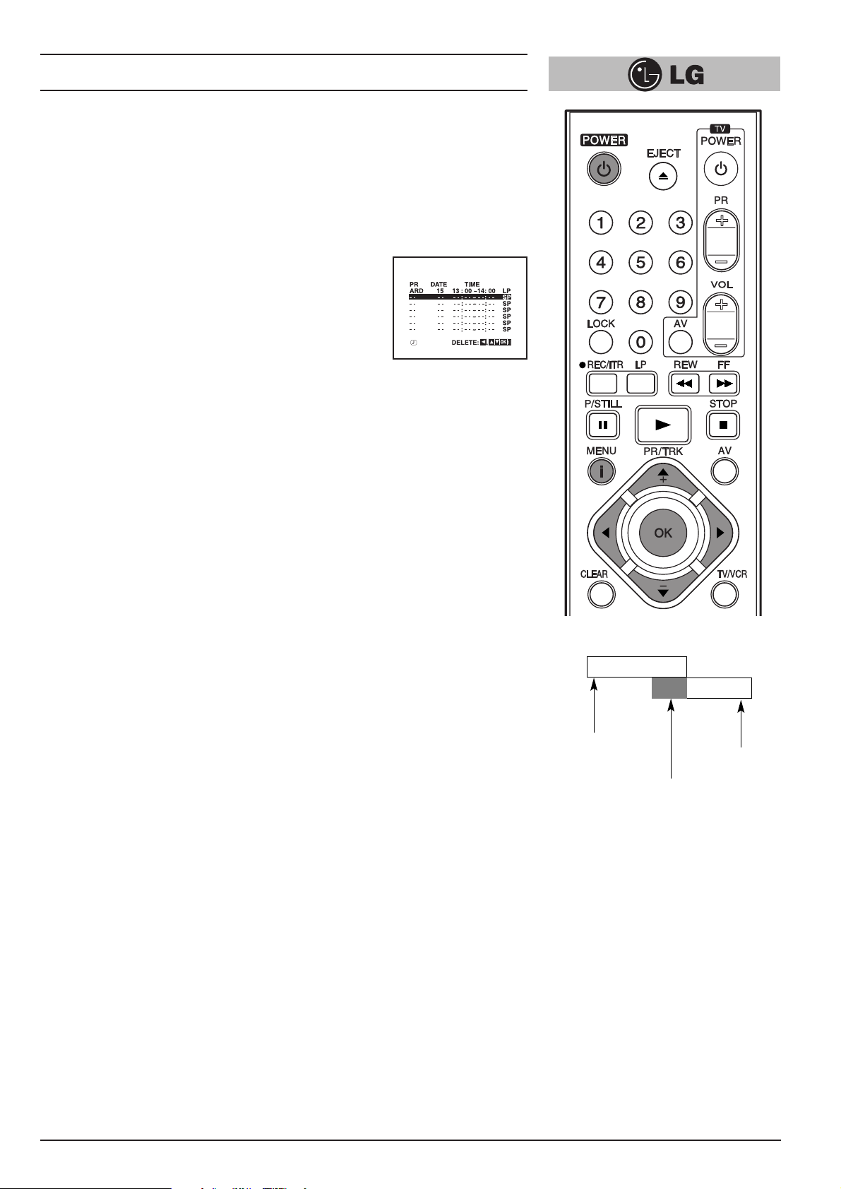
Overlapping timer programmes.
When timer programmes overlap, the programme which is
already recording continues to its scheduled end time.
Hence the beginning of the second programme will not be
recorded.
NOTE - If you wish to stop a timer recording which has
already started, press the “POWER” button.
14:00
15:00
14:30
PROGRAMME 1
PROGRAMME 2
15:30
(This portion will not be recorded)
Page 30

Other features
30
Introduction
This video recorder has a number of other features which make it easier and more
convenient to use. Some of these are described in this section of the manual. Later
sections describe the connection of the video recorder to other equipment, and
features relating on the video recorder.
The features described here are:
1
The On Screen Display of the time or tape counter, date, programme channel
and operation mode of the vide recorder.
2
The Digital Tape Counter and Remaining Tape Volume indicator.
3
The Memory Stop facility that can be used during rewind to stop the tape at a
preset point.
4
The tracking control that optimises the picture quality.
5
The Automatic Playback facility which plays back a tape, rewinds and ejects it
and switches off the video recorder.
6
Automatic Memory Power Shut Off when a video cassette is rewound.
7
A Child Lock facility so that the video recorder can be controlled only from the
handset.
8
The 16:9 wide-screen recording and playback.
9
Self-diagnosis.
Page 31

Other features
31
ON SCREEN DISPLAY OF THE TIME OR TAPE COUNTER, REMAINING TAPE
VOLUME, DATE, PROGRAMME CHANNEL AND OPERATION MODE OF THE
VIDEO RECORDER.
When the “OK” button is pressed, a display occurs on the TV screen of the current
time or the tape counter and the remaining tape volume, the date, year and day of
the week, the programme channel and the operation mode of the video recorder.
The tape counter and the volume of the tape remaining appear only while a tape is
loaded. After two seconds the clock display or the tape counter and the volume of
tape remaining will only remain. If you press the “OK” once again within two seconds
the clock display changes to the tape counter and the volume of the tape remaining
or vice versa. Press the “OK” button again to remove the display from the TV screen.
Note - If a recording is taking place these On Screen displays will not be recorded
onto the tape.
Digital Tape Counter/Remaining Tape Volume
The Digital Tape Counter and Remaining Tape Volume can be displayed on the TV
screen instead of the time by repeatedly pressing the “OK” button.
The Digital Tape Counter gives you the relative positions of recordings on the tape. If
you set the counter to 0:00:00 at the beginning of a tape, you can note the counter
reading at the beginning of each separate recording.
To set the counter to M 0:00:00 press the “CLEAR” button.
The memory stop facility
Memory Stop automatically stops a tape when the tape counter is 0:00:00. This
feature may be used to return the tape to a preselected position immediately after
making a recording, or to repeatedly playback a portion of a tape.
1
Press the “OK” button to set the display to the counter.
2
Before playback or recording, press the “CLEAR” button. The counter will read
M 0:00:00.
3
Begin the playback or recording.
The tape counter gives the actual time in hours, minutes and seconds.
4
Press the “STOP” button when playback or recording is completed.
5
Press the “REW” button. The tape will rewind and automatically stop when the
counter returns to M 0:00:00.
STOP
SP
ARD
1. 01.04 11:00
VCR RECORDER
FUNCTION
CHANNEL
PROGRAMME
DAY/MONTH/
YEAR/DAY OF
THE WEEK
Clock/Tape
counter/Remaining
Tape Volume
THU
Page 32

Other features
32
Tracking Controls
Tracking distortions show up as streaks or an unstable picture. This video recorder
can set the tracking automatically. You can also set the tracking manually if you need
to do so.
Automatic tracking - The automatic tracking adjusts the tracking to playback a tape
with the optimum picture quality. As soon as you start to playback a tape the tracking
will be adjusted if necessary.
Manual tracking - If the quality of the recording is poor, or if the tapes are damaged,
the automatic tracking will not be able to work correctly. In these cases you will have
to remove tracking distortions manually.
You can adjust the tracking during playback with the cursor TRK + and - buttons.
Press them repeatedly until the distortions have been eliminated.
You can switch on the automatic tracking again after using the manual tracking feature
by pressing the “0” button. When you change a video cassette, the automatic tracking
will always be switched on again.
Automatic Playback
Automatic Playback is a very convenient automatic action of this video recorder. It
occurs whenever you insert into the video recorder a video cassette from which the
safety tab has been removed (e.g. a video cassette which you have hired).
Automatic Playback carries out the following procedures:
It automatically switches on the video recorder’s power and starts to playback the
tape.
At the end of the tape, it automatically rewinds.
The tape is ejected automatically.
The video recorder switches itself off.
Automatic Memory Power Shut-Off
This feature of the video recorder enables you to initiate switching off the video
recorder during tape rewind. Hence you do not have to wait until a tape has rewound
before you can switch the video recorder off.
To activate Automatic Memory Power Shut Off press the “POWER” button during tape
rewind. The tape will rewind to the beginning and the video recorder will switch itself
off.
Pressing any of the control buttons (e.g. “POWER” or “PLAY”) after setting Automatic
Memory Power Shut Off will cancel it.
Page 33

Other features
33
The Child Lock
The control buttons on the front of the video recorder are inoperative. The video
recorder can be controlled only from the handset.
1
Press the “LOCK” button. SAFE will appear on the TV screen. SAFE
will flicker in your video recorder’s display for a few seconds.
The control buttons on the front of the video recorder are inoperative (except for
“STOP/EJECT”). The video recorder can be controlled only from the handset.
If any buttons on the front of your VCR are pressed SAFE will appear in your
video recorder’s display and on the TV screen for a few seconds.
2
To switch off the locking, press the “LOCK” button again.
OFF will flicker in your video recorder’s display for a few seconds.
16:9 Compatibility (Wide - screen TV)
This video recorder can be recorded and played back the 16:9 wide aspect ratio
programmes.
Select the required position in the main menu as described on page 11:
To record in a wide-screen format, you have to set to “16:9”, or if you set to “4:3” the
video recorder will be recorded in normal format.
When you set to “AUTO”, the video recorder will be automatically played back the
wide-screen programmes as wide, the normal programmes as normal.
Self-Diagnosis
This function informs you of an error messages for solving the problems more easily.
1
Press the “i” button on the remote control handset. The menu will appear on the
TV screen.
2
Select “Dr.” with the cursor “F” and “G” buttons and press the “OK” button.
3
Check a problem with the cursor “D” and “E” buttons.
4
Press the “i” button.
NOTE:
When the picture disappears on the TV screen while playing back a 16:9
programme or recording in 16:9 format, set the TV to “AV” mode.
Menu of Video Doctor Status of Display Solution & Information
HEAD STATUS PLEASE CLEAN Clean your video heads
TAPE STATUS NOT RECORDABLE Insert a tape with its
protection tab in place
NO.OF TIMER 1 Shows the number of timer
PROGRAMME recording
NEXT TIMER PROGRAMME
ARD 26 10:00~ 11:00 SP
Shows the status of
current timer recording
G
SORTIE
AUDIO
OUT
L
ENTREE
EURO AV2 DECODER
ANTENNE
AERIAL
EURO AV1 AUDIO/VIDEO
SORTIE
ANTENNE
RF.OUT
Wide - screen TV
D
R
VCR
VIDEO DOCTOR
Dr.
HEAD STATUS
TAPE STATUS
NO. OF TIMER PROGRAMME
NEXT TIMER PROGRAMME
OK
i
Page 34

The Hi-Fi stereo sound system
34
Introduction
This video recorder will record and playback Hi-Fi stereo sound. There are, therefore,
several possible ways of recording and playing back the sound. These are described
below.
The audio tracks
Video cassette tapes recorded on this video recorder will have a normal mono audio
track and two video tape Hi-Fi stereo audio tracks. These allow you to make audio
recordings in Hi-Fi stereo or bilingual mode from a TV broadcast, a stereo audio
system, a video disc or another video recorder.
Using your video recorder in combination with a Hi-Fi audio system will enhance the
sound quality of video tapes.
Stereo, bilingual, mono
STEREO AUDIO RECORDING- A TV broadcast being transmitted in stereo sound
mode will display STEREO on the TV screen. During recording stereo sound will
automatically be recorded on the Hi-Fi stereo tracks of the video tape, and in mono on
the mono track.
BILINGUAL AUDIO RECORDING- A TV broadcast being transmitted in bilingual
sound will display BIL on the TV screen. Both audio channels will automatically be
recorded on the Hi-Fi stereo tracks of the video tape, and the main channel (left) will
be recorded on the mono track.
Audio output during playback
The audio output mode during playback is that chosen “AUDIO” in the main menu.
The choice is STEREO, LEFT (left channel), RIGHT (right channel) or MONO.
Note- that whilst adjusting the auto tracking control Hi-Fi stereo sound may revert to
mono sound
BILINGUAL AUDIO OUTPUT - If the audio output is bilingual the primary language is
output from the left channel, and the secondary language is output simultaneously
from the right channel when the audio setting is STEREO. The primary language is
output from both channels when the audio setting is MONO.
AUDIO TRACKS
MONO Hi-Fi TRACKS
TRACK L-CH R-CH
STEREO L+R-CH L-CH R-CH
L-CH L-CH R-CH
BILINGUAL
(Main) (Main) (Sub)
MONO MONO MONO MONO
TYPE OF
BROADCAST
Page 35

Recording from another equipment
35
Simulcast stereo recording and playback Recording
Some TV programmes is also broadcast in stereo sound on FM radio. For these
simulcast broadcasts you can record the picture from the TV programme, and the
sound from your audio system as follows:
1
Connect your audio system to the “AUDIO IN (L/R)” on the front of the video
recorder.
2
Select “SC” mode with the “AV” button on the remote control handset.
3
Select the programme to be recorded with the handset.
4
Turn on your audio system and tune in to the sound broadcast.
5
Start recording.
NOTE: The Simulcast Stereo audio will be recorded on the Hi-Fi Audio tracks.
The Normal (Mono) audio track will record the TV programme FM mono
sound.
PLAYBACK
You can play back the stereo sound through a stereo TV set. To playback the stereo
sound through your audio system, connect it to the “AUDIO OUT” terminals on the
back of the video recorder. Turn off the sound on your TV set.
Recording from a second video recorder (for tape copying)
1
A second video recorder (for tape copying) should be connected to the “AUDIO
IN (L/R)” and VIDEO IN terminals on the front of the video recorder or one of the
EURO SCART sockets on the back.
2
The appropriate audio/video mode should be set with the “AV” button.
3
Insert an empty cassette into this video recorder, and if you are copying another
tape insert it into the second video recorder.
4
Start recording on this video recorder, and if appropriate, the playback at the
second video recorder.
NOTE - Unauthorised recording of copyrighted TV programmes, films video
cassette and other materials may infringe the rights of copyright owners and
be contrary to copyright laws.
VIDEO IN L(MONO)-AUDIO IN-R
FM
AM
300•ÿ
FM
75•ÿ
RL
To AUDIO OUT
(L/R)
VIDEO IN L- AUDIO IN -R
To AUDIO IN (L/R)
G
SORTIE
D
AUDIO
OUT
L
R
ENTREE
EURO AV2 DECODER
ANTENNE
AERIAL
EURO AV1 AUDIO/VIDEO
SORTIE
ANTENNE
RF.OUT
EURO AV1
AERIAL
AUDIO OUT
R
L
RF. OUT
Page 36

ez (easy) power off
The sequence of “Stop Rewind Eject Power Off ” is operated automatically
by pressing ez POWER OFF.
1
During play back press ez POWER OFF.
2
Your VCR will be operated as the following;
ez (easy) repeat
By pressing & holding ez REPEAT during play back, the holding section is replayed
twice automatically.
1
During play back, press & hold ez REPEAT at the point where repeat play is to
be concluded.
2
Then, your VCR will go into reverse search.
3
Release ez REPEAT at the point where repeat play is to start.
4
The holding section is replayed twice automatically.
5
Pressing ez REPEAT again during repeat play, will return to normal play.
ez (easy) operations
36
STOP REWIND
EJECT
POWER
OFF
Page 37

Controlling the TV
37
You can control the sound level, input source, and power switch of your LG TV with the
supplied remote control.
You can control your TV using the buttons below
By pressing You can
TV POWER Turns the TV on or off..
TV PR +/– Scans up or down through memorized channels.
TV VOL +/– Adjust the volume of the TV.
TV AV Switch the TV’s input source between the TV and other input
sources
Controlling other TVs with the remote control
You can control the sound level, input source, and power switch of non-LG TVs as
well. If your TV is listed in the table below, set the appropriate manufacturer code.
1
While holding down TV POWER button, press the number buttons to select the
manufacturer code for your TV (see the table below).
2
Release TV POWER button.
Code numbers of controllable TVs
If more than one code number is listed, try entering them one at a time until you find
the one that works with your TV.
Manufacturer Code Number
LG / GoldStar 1 (Default), 2
Zenith 1, 3, 4
Samsung 6, 7
Sony 8, 9
Hitachi 4
NOTES:
O Depending on your TV, some or all buttons may not function on the TV, even after
entering the correct manufacturer code.
O If you enter a new code number, the code number previously entered will be erased.
O When you replace the batteries of the remote, the code number you have set may
be reset to the default setting. Set the appropriate code number again.
Page 38

38
Specifications
General
Power : 200-240V~, 50Hz.
Power consumption : Approx. 12 watts (Energy saving mode: 3 watts)
Video Head system : Double azimuth 4 heads, helical scanning system
Tape speed : 23.39 mm/sec (SP mode)/11.69 mm/sec (LP mode)
Tape format : Tape width 1/2" (12.7 mm high density Video tape)
Maximum recording time : 4 hours in SP mode/8 hours in LP mode
(with E-240 tape)
Rewind time : Approx. 65(±10) sec. (with E-180 tape)
Dimensions (W X H X D) : 14.2" X 3.2" X 9.1" (360 X 82 X 230 mm)
Weight : 2.87 kg
Operating temperature : 41°F-95°F (5°C-35°C)
Operating humidity : Less than 80 %
Timer : 24 hours display type
Video
Television system : CCIR standard (625 lines, 50 fields) PAL (B/G),
SECAM (B/G) colour signal
Recording format : PAL/MESECAM
RF reception : PAL B/G, SECAM B/G
RF OUT : PAL G
Input level : VIDEO IN (SCART, RCA type)
1.0 Vp-p, 75 ohm, unbalanced
Output level : VIDEO OUT (SCART type)
1.0 Vp-p, 75 ohm, unbalanced
Signal to noise ratio : More than 43 dBm
RF modulator : UHF channels 22-68 (Adjustable)
Audio
Input level : AUDIO IN (SCART, RCA type)
Scart type: -6.0 dBm, more than 10 kΩ
RCA type: -6.0 dBm, more than 47 kΩ
Output level : AUDIO OUT (SCART, RCA type)
Scart type: -6.0 dBm, less than 1 kΩ
RCA type: -6.0 dBm, less than 1 kΩ
Audio track : Mono track & Hi-Fi track
Audio frequency response : Normal:100 Hz-10 kHz (-6/+3 dBm)
Hi-Fi: 20 Hz-20 kHz (-3/+3 dBm)
Audio signal to noise ratio : Normal audio: More than 43 dB (at SP mode)
Hi-Fi audio: More than 70 dB (at SP mode)
Audio dynamic range : Hi-Fi audio: More than 85 dB (at SP mode)
● Design and specifications are subject to change without notice!
Page 39

39
Before calling for service...
Please check to see if any problem which you may have with your video recorder is
described here before taking it for service or calling a service engineer.
Problem Possible solution?
No mains power to the recorder • Is the video recorder plugged into the
mains?
• Is the mains supply on and switched
on?
TV programmes cannot be recorded • Can you get a picture on the TV
screen?
• If are not the aerial and RF lead
connected?
• Are the TV channels properly tuned in?
• Has the safety tab been removed from
the video cassette to prevent recording?
A timer recording does not take place • Is POWER off?(Is the “TIMER” showing
in the display?)
• Were the recording start and end times
set correctly?
• Are the timer settings in the timer
menu?
• Was the power interrupted after setting
the timer?
If so the time setting will be erased and
timer recordings will not take place.
AUTO PLAY does not work • Has the safety tab been removed from
the video cassette?
There is no picture on playback, or it is • Are the TV channels properly tuned in?
noisy and streaky • Try another video cassette.
• Can you minimise the noise bars to an
acceptable level with the “0” or “
D” and
“
E” buttons?
The top of the playback picture is • Is the video cassette damaged?
unstable Try another one.
• Adjust the horizontal hold control on
you TV set.
• Insure that you are using the “video”
channel on your TV set example 0, 8, 9
or 12.
Video cassettes cannot be inserted • Is the cassette compartment empty?
• Are you trying to insert the cassette the
right way round?
No Hi-Fi sound • Switch “AUDIO” in the main menu to
“STEREO”.
Video Head Cleaning
Whenever a video cassette is inserted into or ejected from your Video the video head
is automatically cleaned. This should mean that additional head cleaning should not
be necessary. However dirt accumulating on the head after a long period of time can
cause the playback picture to become blurred or broken up. High quality video cassette tapes will not normally deposit dirt onto the video head, but old or damaged
tapes might.
Page 40

LG Electronics Deutschland GmbH
Jakob-Kaiser-Straße 12
Postfach 244, 47877 Willich
Telefon: 02154 / 492-0, Telefax: 02154 / 428799
Internet: www.lge.de
P/N: MFL46896863
 Loading...