

LG LV240HV4, LV180HV4, LV420HV, LV360HV4, LV480HV Installation Manual
LV180HV4
LV240HV4
SINGLE ZONE
VERTICAL AIR HANDLING UNIT
INSTALLATION MANUAL
LV360HV4 LV420HV LV480HV

PROPRIETARY DATA NOTICE
This document, as well as all reports, illustrations, data, information, and
other materials are the property of LG Electronics U.S.A., Inc., and are
disclosed by LG Electronics U.S.A., Inc., only in confidence.
This document is for design purposes only.
Do not throw away, destroy, or lose this manual.
Please read carefully and store in a safe place for future reference.
Content familiarity required for proper installation.
The instructions included in this manual must be followed to prevent product malfunction, property damage, injury, or death to the user or
other people. Incorrect operation due to ignoring any instructions will cause harm or damage. The level of seriousness is classified by the
symbols described below.
A summary list of safety precautions begins on page 3.
For more technical materials such as submittals, engineering
databooks, and catalogs, visit www.lghvac.com.
For continual product development, LG Electronics U.S.A., Inc., reserves the right to change specifications without notice.
This document, as well as all reports, illustrations, data, information, and other materials are the property of LG Electronics U.S.A., Inc.
IM_SZ_VAHU_12_17
©LG Electronics U.S.A., Inc.
SAFETY INSTRUCTIONS
DANGER
The instructions below must be followed to prevent product malfunction, property damage, injury or death to the user or other people. Incorrect operation due to ignoring any instructions will cause harm or damage. The level of seriousness is classified by the symbols described
below.
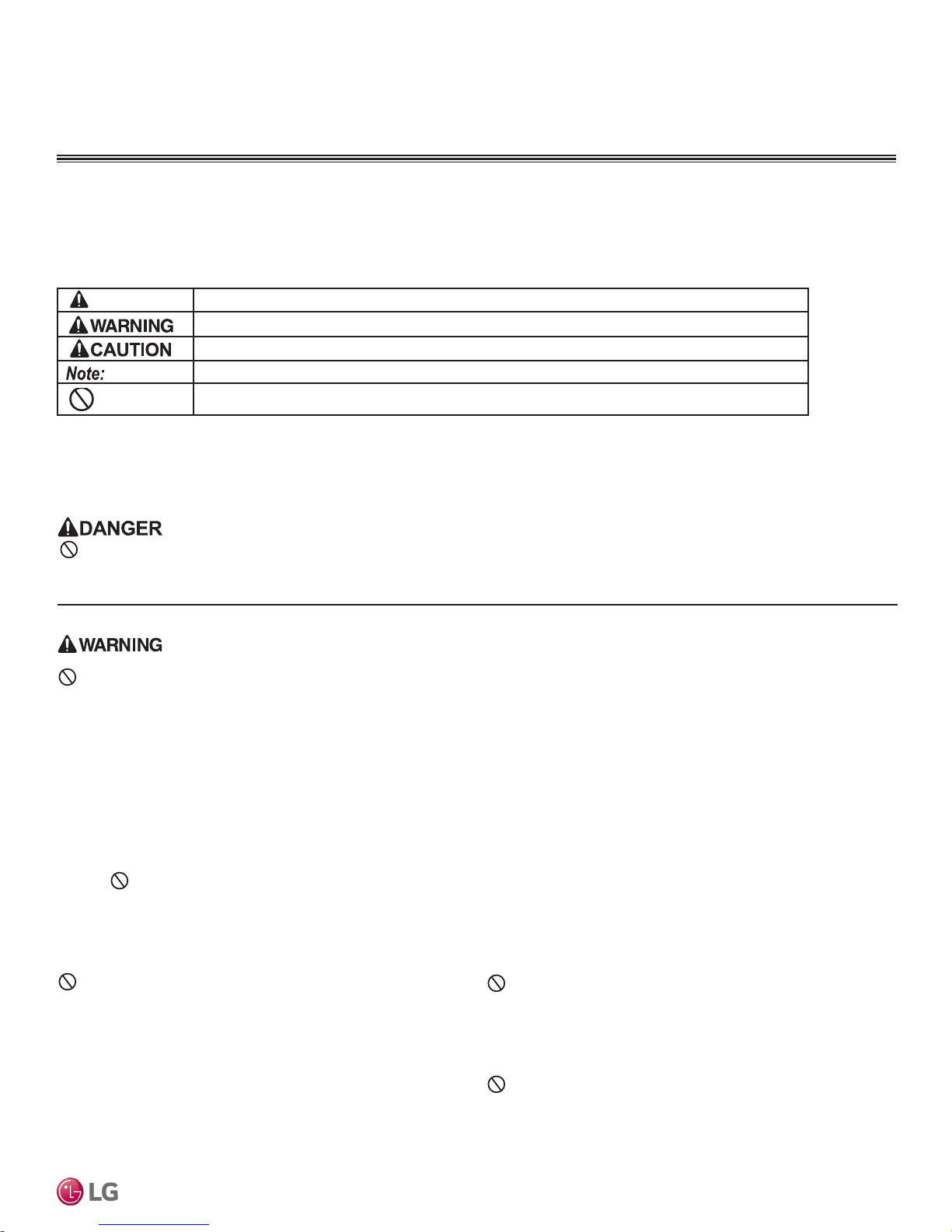
TABLE OF SYMBOLS
This symbol indicates an imminently hazardous situation which, if not avoided, will result in death or serious injury.
This symbol indicates a potentially hazardous situation which, if not avoided, could result in death or serious injury.
This symbol indicates a potentially hazardous situation which, if not avoided, may result in minor or moderate injury.
This symbol indicates situations that may result in equipment or property damage accidents only.
This symbol indicates an action that must not be completed.
INSTALLATION
Don’t store or use ammable gas / combustibles near the unit.
There is risk of re, explosion, and physical injury or death.
Do not install or remove the unit by yourself (end user).
Ask the dealer or an LG trained service provider to install the
unit.
Improper installation by the user may result in water leakage, re,
explosion, electric shock, physical injury or death.
For replacement of an installed unit, always contact an LG
trained service provider.
There is risk of re, electric shock, explosion, and physical injury or
death.
The unit is shipped with refrigerant and the service valves
closed.
non-condensibles have been removed from the piping system and authorization to do so has been obtained from the
commissioning agent.
There is a risk of physical injury or death.
Do not open service valves on the unit until all
Safety Instructions
Always check for system refrigerant leaks after the unit has
been installed or serviced.
Exposure to high concentration levels of refrigerant gas may lead to
illness or death.
Wear protective gloves and safety goggles when handling
equipment. Sharp edges may cause personal injury.
Dispose the packing materials safely.
• Packing materials, such as nails and other metal or wooden parts,
may cause puncture wounds or other injuries.
• Tear apart and throw away plastic packaging bags so that children
may not play with them and risk suffocation and death.
Install the unit considering the potential for strong winds or
earthquakes.
Improper installation may cause the unit to fall over, resulting in physical
injury or death.
Do not operate the compressor with the service valves
closed.
There is a risk of explosion, physical injury, or death.
Periodically check that the outdoor frame is not damaged.
There is a risk of explosion, physical injury, or death.
Conrm all control box and panel covers are secure and
intact.
If cover panels are not installed securely, dust, water and animals may
enter the unit, causing re, electric shock, and physical injury or death.
Due to our policy of continuous product innovation, some specifications may change without notification.
©LG Electronics U.S.A., Inc., Englewood Cliffs, NJ. All rights reserved. “LG” is a registered trademark of LG Corp.
Do not change the settings of the protection devices.
If the pressure switch, thermal switch, or other protection device is
shorted and forced to operate improperly, or parts other than those
specied by LG are used, there is risk of re, electric shock, explosion,
and physical injury or death.
Do not install the unit on a defective stand.
There is a risk of physical injury.
3
SAFETY INSTRUCTIONS
INSTALLATION - CONTINUED
If the air conditioner is installed in a small space, take
measures to prevent the refrigerant concentration from
exceeding safety limits in the event of a refrigerant leak.
Install the unit in a safe location where nobody can step on or
fall onto it.
There is risk of physical injury or death.
Consult the latest edition of ASHRAE (American Society of Heating,
Refrigerating, and Air Conditioning Engineers) Standard 15. If the
refrigerant leaks and safety limits are exceeded, it could result in personal injuries or death from oxygen depletion.
Properly insulate all cold surfaces to prevent “sweating.”
Cold surfaces such as uninsulated piping can generate condensate
that could drip, causing a slippery surface that creates a risk of slipping,
falling, and personal injury.
Be very careful when transporting the product.
• Do not attempt to carry the product without assistance.
• Some products use polypropylene bands for packaging. Do not use polypropylene bands to lift the unit.
• Suspend the unit from the base at specified positions.
• Support the unit a minimum of four points to avoid slippage from rigging apparatus.
Do not install the unit in a noise sensitive area.
Don’t install the unit where it’s directly exposed to ocean
winds.
When connecting refrigerant tubing, remember to allow for
pipe expansion.
Improper piping may cause refrigerant leaks and system malfunction.
Ocean winds may cause corrosion, particularly on the condenser and
evaporator ns, which, in turn could cause product malfunction or inefcient performance.
When installing the unit in a low-lying area, or a location that
is not level, use a raised concrete pad or concrete blocks to
provide a solid, level foundation.
This may prevent water damage and reduce abnormal vibration.
Take appropriate actions at the end of HVAC equipment life
to recover, recycle, reclaim or destroy R410A refrigerant
according to applicable U.S. Environmental Protection
Agency (EPA) rules.
Periodically check that the outdoor frame is not damaged.
There is a risk of equipment damage.
Properly insulate all cold surfaces to prevent “sweating.”
Cold surfaces such as uninsulated piping can generate condensate that
may drip and cause a slippery surface condition and/or water damage to
walls.
When installing the unit in a hospital, mechanical room, or
similar electromagnetic eld (EMF) sensitive environment,
provide sufcient protection against electrical noise.
Inverter equipment, power generators, high-frequency medical equip-
Single Zone Vertical Air Handling Unit Installation Manual
ment, or radio communication equipment may cause the air conditioner to
operate improperly. The unit may also affect such equipment by creating
electrical noise that disturbs medical treatment or image broadcasting.
Do not use the product for special purposes such as
preserving foods, works of art, wine coolers, or other
precision air conditioning applications. The equipment is
designed to provide comfort cooling and heating.
There is risk of property damage.
Do not make refrigerant substitutions. Use R410A only.
If a different refrigerant is used, or air mixes with original refrigerant, the
unit will malfunction and be damaged.
Keep the unit upright during installation to avoid vibration or
water leakage.
Due to our policy of continuous product innovation, some specifications may change without notification.
4
©LG Electronics U.S.A., Inc., Englewood Cliffs, NJ. All rights reserved. “LG” is a registered trademark of LG Corp.
Install the unit in a safe location where nobody can step on or
fall onto it.
Do not install the unit on a defective stand.
There is risk of unit and property damage.
Install the drain hose to ensure adequate drainage.
There is a risk of water leakage and property damage.
Don’t store or use ammable gas / combustibles near the
unit.
There is risk of product failure.
Always check for system refrigerant leaks after the unit has
been installed or serviced.
Low refrigerant levels may cause product failure
The unit is shipped with refrigerant and the service valves
closed.
non-condensibles have been removed from the piping system
and authorization to do so has been obtained from the commissioning agent.
Do not open service valves on the unit until all
There is a risk of refrigerant contamination, refrigerant loss and equipment damage.
Do not run the compressor with the service valves closed.
There is a risk of equipment damage.
WIRING
High voltage electricity is required to operate this system.
Adhere to the National Electrical Codes and these
instructions when wiring.
Improper connections and inadequate grounding can cause accidental
injury or death.
Always ground the unit following local, state, and National
Electrical Codes.
The information contained in this manual is intended for use
by an industry-qualied, experienced, certied electrician
familiar with the U.S. National Electric Code (NEC) who is
equipped with the proper tools and test instruments.
Failure to carefully read and follow all instructions in this manual can
result in equipment malfunction, property damage, personal injury or
death.
SAFETY INSTRUCTIONS
Turn the power off at the nearest disconnect before servicing
the equipment.
Electrical shock can cause physical injury or death.
Properly size all circuit breakers or fuses.
There is risk of re, electric shock, explosion, physical injury or death.
Refer to local, state, and federal codes, and use power wires
of sufcient current capacity and rating.
Wires that are too small may generate heat and cause a re.
Secure all eld wiring connections with appropriate wire
strain relief.
Improperly securing wires will create undue stress on equipment power
lugs. Inadequate connections may generate heat, cause a re and
physical injury or death.
Safety Instructions
All electric work must be performed by a licensed electrician
and conform to local building codes or, in the absence of
local codes, with the National Electrical Code, and the
instructions given in this manual.
If the power source capacity is inadequate or the electric work is not
performed properly, it may result in re, electric shock, physical injury or
death.
Due to our policy of continuous product innovation, some specifications may change without notification.
©LG Electronics U.S.A., Inc., Englewood Cliffs, NJ. All rights reserved. “LG” is a registered trademark of LG Corp.
5
SAFETY INSTRUCTIONS
OPERATION
Do not provide power to or operate the unit if it is ood-
ed or submerged.
There is risk of re, electric shock, physical injury or death.
Use a dedicated power source for this product.
There is risk of re, electric shock, physical injury or death.
Do not allow water, dirt, or animals to enter the unit.
There is risk of re, electric shock, physical injury or death.
Do not operate the disconnect switch with wet hands.
There is risk of re, electric shock, physical injury or death.
If gas leaks out, ventilate the area before operating the unit.
If the unit is mounted in an enclosed, low-lying, or poorly ventilated area,
and the system develops a refrigerant leak, it may cause re, electric
shock, explosion, physical injury, or death.
Periodically check power wiring for damage.
Power wiring must be replaced by the manufacturer, its service agent, or
similar qualied persons in order to avoid physical injury and/or electric
shock.
Avoid excessive cooling and periodically perform ventilation
to the unit.
Inadequate ventilation is a health hazard.
Do not touch the refrigerant piping during or after
operation.
It can cause burns or frostbite.
Do not operate the unit with the panel(s) or protective
cover(s) removed; keep ngers and clothing away from
moving parts.
The rotating, hot, cold, and high-voltage parts of the unit can cause
Do not open the inlet grille of the unit during operation.
Do not operate the unit with the panels or guards removed.
inlet or outlet when the unit has power applied to it.
not touch the electrostatic lter, if the unit includes one.
The unit contains sharp, rotating, hot, and high voltage parts that can
cause personal injury and/or electric shock.
Securely attach the electrical part cover to the indoor unit
and the service panel to the outdoor unit.
Non-secured covers can result in burns or electric shock due to dust or
water in the service panel.
physical injury or death.
Periodically verify the equipment mounts have not
deteriorated.
If the base collapses, the unit could fall and cause physical injury or
death.
To avoid physical injury, use caution when cleaning or servicing the air conditioner.
Single Zone Vertical Air Handling Unit Installation Manual
Clean up the site after installation is nished, and check
that no metal scraps, screws, or bits of wiring have been left
inside or surrounding the unit.
Securely attach the electrical part cover to the indoor unit
and the service panel to the outdoor unit.
Non-secured covers can result in malfunction due to dust or water in the
service panel.
Do not insert hands or other objects through the
Do
Do not use this equipment in mission critical or specialpurpose applications such as preserving foods, works of art,
wine coolers or refrigeration. The equipment is designed to
provide comfort cooling and heating.
Oil, steam, sulfuric smoke, etc., can signicantly reduce the performance
of the unit, or damage its parts.
Do not block the inlet or outlet.
Unit may malfunction.
Due to our policy of continuous product innovation, some specifications may change without notification.
6
©LG Electronics U.S.A., Inc., Englewood Cliffs, NJ. All rights reserved. “LG” is a registered trademark of LG Corp.
Periodically verify the equipment mounts have not
deteriorated.
If the base collapses, the unit could fall and cause property damage
or product failure.
Do not allow water, dirt, or animals to enter the unit.
There is risk of unit failure.

TABLE OF CONTENTS
General Data ..............................................................................................................................................8
Unit Nomenclature ................................................................................................................................... 8
Specications ..........................................................................................................................................9
Electrical ................................................................................................................................................ 11
Location Selection ................................................................................................................................. 12
General Installation Guidelines .............................................................................................................. 14
Oceanside Applications ......................................................................................................................... 14
Required Outdoor Unit Clearances .......................................................................................................15
Required Indoor Unit Clearances .......................................................................................................... 20
Horizontal Right Installation ................................................................................................................... 22
Vertical Downow Installation ................................................................................................................23
Installing Ductwork ................................................................................................................................26
Refrigerant Safety/Device Connection Limitations ................................................................................ 27
Selecting Field Supplied Piping ............................................................................................................. 28
Copper Expansion and Contraction .......................................................................................................29
Piping Handling .....................................................................................................................................31
Refrigerant System Engineering ............................................................................................................32
Flaring and Brazing Procedures ............................................................................................................ 35
Refrigerant Piping Connections .............................................................................................................37
Installation Overview .............................................................................................................................37
Directional Pipe Formation .................................................................................................................... 38
Outdoor Unit Connections ..................................................................................................................... 39
Indoor Unit Connections ........................................................................................................................ 40
Drain Hose .............................................................................................................................................41
Bundling and Cutting Line .....................................................................................................................42
Electrical System Installation ................................................................................................................. 45
General Information and Safety Guidelines ...........................................................................................45
Power Wiring Specications and Best Practices ................................................................................... 46
Wall Controller Installation .....................................................................................................................49
External Static Pressure Setting Values ................................................................................................ 50
Indoor Unit Electrical Connections ........................................................................................................51
Outdoor Unit Electrical Connections ......................................................................................................52
Indoor Unit Wiring Diagram ................................................................................................................... 53
Outdoor Unit Wiring Diagram LUU188HV, LUU248HV ......................................................................... 54
Outdoor Unit Wiring Diagram LUU368HV, LUU428HV, LUU488HV 55
NK/NJ Chassis Wiring Diagram Legend ................................................................................................56
NJ/NK Chassis DIP Switch Settings ...................................................................................................... 57
Final Installation Procedures .................................................................................................................58
Triple Leak / Pressure Check ................................................................................................................58
Triple Leak / Pressure and Evacuation Procedures ..............................................................................59
Triple Evacuation Procedure .................................................................................................................60
Trim Charge, Test Run ........................................................................................................................... 61
Pump Down, Cooling Only Mode ..........................................................................................................62
LG SIMS - Self Diagnosis Functions .................................................................................................... 63
Error Codes .......................................................................................................................................... 65
Refrigerant Leaks .................................................................................................................................. 67
Installation Checklist ...............................................................................................................................68
Due to our policy of continuous product innovation, some specifications may change without notification.
©LG Electronics U.S.A., Inc., Englewood Cliffs, NJ. All rights reserved. “LG” is a registered trademark of LG Corp.
7
GENERAL DATA
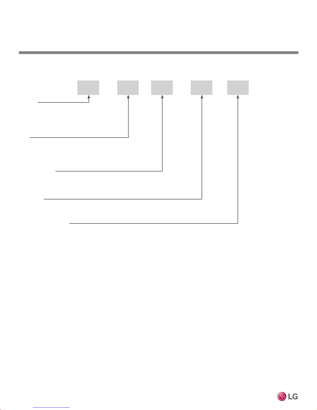
Unit Nomenclature
Single Zone Vertical Air Handling Indoor and Outdoor Units
LV N 24 HV4
Family
L = LG
U = Single Zone Universal
V = Vertical Air Handling Unit
Type
N = Indoor Unit
U = Outdoor Heat Pump Unit
Nominal Capacity
(Nominal cooling capacity in Btu/h)
18 = 18,000 24 = 24,000 36 = 36,000 42 = 42,000 48 = 48,000
Generation
Indoor/Outdoor Product
H = Heat Pump
V = Inverter
4 = Generation 4/Multi Compatible
0
Single Zone Vertical Air Handling Unit Installation Manual
Due to our policy of continuous product innovation, some specifications may change without notification.
8
©LG Electronics U.S.A., Inc., Englewood Cliffs, NJ. All rights reserved. “LG” is a registered trademark of LG Corp.
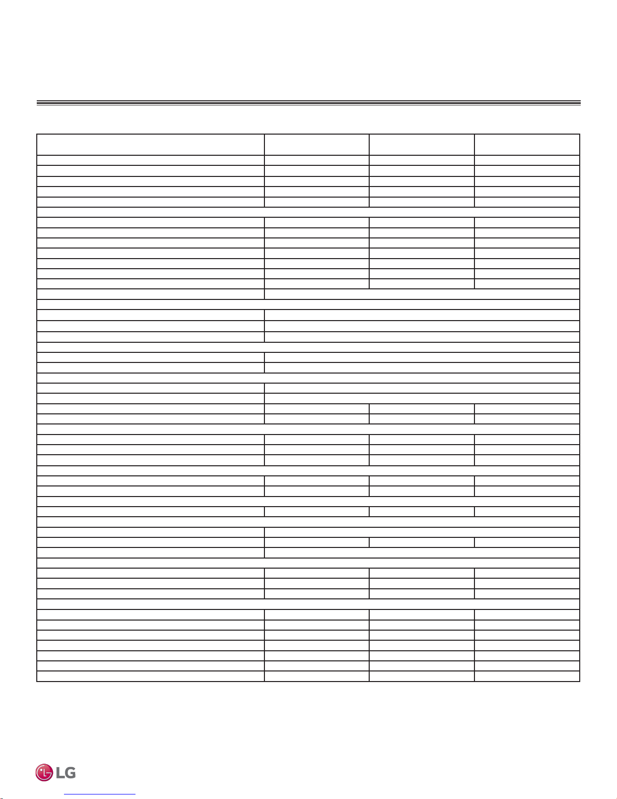
Table 1: Single Zone Vertical Air Handling Unit Specications
System (Model) (Indoor Unit / Outdoor Unit)
Cooling Capacity1 (Min/Rated/Max) (Btu/h) 8,000 ~ 18,000 ~ 24,000 9,000 ~ 24,000 ~ 28,000 14,000 ~ 36,000 ~ 44,000
Cooling Power Input
Heating Capacity (Min/Rated/Max) (Btu/h) 9,000 ~ 20,000 ~ 23,000 10,000 ~ 27,000 ~ 30,000 15,000 ~ 40,000 ~ 47,000
Heating Power Input
COP (OD 47°F) 3.66 3.50 3.46
Maximum Heating Capacity (Btu/h)
Outdoor 17°F (WB)/Indoor 70°F (DB) 18,000 22,000 32,000
Outdoor 5°F (WB)/Indoor 70°F (DB) 16,000 20,000 30,000
Power Input [W] @ Outdoor 5℉ (WB) 2,500 3,200 4,400
Outdoor -4°F (WB)/Indoor 70°F (DB) 11,000 15,000 22,000
EER (OD 95°F) 13.33 12.50 12.50
SEER 19.0 18.0 18.0
HSPF 9.5 10.0 10.0
Power Supply V, Hz, Ø
Outdoor Unit Operating Range
Cooling (°F DB) 5 - 118
Optional Wind Baffle - Cooling(°F DB) Yes (-4)
Heating (°F WB) -4 - 64
Indoor Unit Operating Range
Cooling (°F WB) 57-77
Heating (°F DB) 59-81
Unit Data
Refrigerant Type
Refrigerant Control EEV
IDU Sound Pressure Level dB(A) (H/M/L)
ODU Sound Pressure Level dB(A) (Cool/Heat)
Unit Weight (lbs.)
IDU (Net/Shipping) 129 / 140 129 / 140 165 / 188
ODU (Net/Shipping) 129 / 141 129 / 141 203 / 232
Power Wiring / Communications Cable (No. x AWG)
Compressor
Compressor (Qty.) Twin Rotary (1) Twin Rotary (1) Twin Rotary (1)
Compressor Oil PVE PVE PVE
Dehumidification
Pints/Hour 2 2.5 3.4
Fan
IDU Type x Qty. Sirocco x 1
ODU Type x Qty. Propeller x 1 Propeller x 1 Propeller x 2
Motor / Drive Brushless Digitally Controlled/Direct
Airflow Rate
IDU (H / M / L [CFM]) 640 / 580 / 480 710 / 640 / 480 1,100 / 1,000 / 900
ODU (Max. [CFM]) 2,048 2,048 1,942 x 2
Factory Set (High) External Static Pressure (in.wg) 0.3 0.3 0.3
Piping
Liquid (in.) 3/8 3/8 3/8
Vapor (in.) 5/8 5/8 5/8
IDU Condensate Drain, Primary & Secondary O.D. (in.) 3/4 FPT 3/4 FPT 3/4 FPT
Additional Refrigerant Charge (oz./ft.) 0.43 0.43 0.43
Pipe Length
Piping Length
Max. Elevation Difference (ft.) 98.4 98.4 98.4
Cooling capacity rating obtained with air entering the indoor unit at 80ºF dry bulb (DB) and 67ºF wet
bulb (WB) and outdoor ambient conditions of 95ºF dry bulb (DB) and 75ºF wet bulb (WB).
Heating capacity rating obtained with air entering the indoor unit at 70ºF dry bulb (DB) and 59ºF wet
bulb (WB) and outdoor ambient conditions of 47ºF dry bulb (DB) and 43ºF wet bulb (WB).
This data is rated 0 ft above sea level with 24.6 of refrigerant line per indoor unit and a 0 ft level
difference outdoor and indoor units.
This unit comes with a dry nitrogen charge.
1
Power Input is rated at high speed.
2
Power wiring to the ODU is field supplied, solid or stranded, and must comply with the applicable local
1
(Min/Rated/Max) (kW) 0.65 ~ 1.35 ~ 2.70 0.70 ~ 1.92 ~ 3.20 1.25 ~ 2.88 ~ 4.80
1
(Rated) (kW) 0.65 ~ 1.60 ~ 2.10 0.75 ~ 2.26 ~ 2.80 1.35 ~ 3.39 ~ 5.05
2
208-230/60/1
3
4
5
42 / 42 / 41 43 / 42 / 41 45 / 44 / 43
5
7
(Minimum/ Maximum) (ft.) 6.6/164 6.6/164 6.6/246
7
(no add’l refrigerant, ft.) 24.6 24.6 24.6
Due to our policy of continuous product innovation, some specifications may change without notification.
©LG Electronics U.S.A., Inc., Englewood Cliffs, NJ. All rights reserved. “LG” is a registered trademark of LG Corp.
GENERAL DATA
Specications
LV180HV4
(LVN180HV4/LUU188HV)
48 / 52 48 / 52 52 / 54
6
3 x 12 / 4 x 18 3 x 12 / 4 x 18 3 x 10 / 4 x 18
and national codes.
3
Low Ambient Wind Baffle Kit allows operation down to 0°F in cooling mode.
4
Take appropriate actions at the end of HVAC equipment life to recover, recycle, reclaim or destroy R410A
refrigerant according to applicable regulations (40 CFR Part 82, Subpart F) under section 608 of CAA.
5
Sound pressure levels are tested in an anechoic chamber under ISO Standard 3745.
6
All power/communication cables from the ODU to the IDU to be minimum 18 AWG, 4-conductor,
stranded, shielded or unshielded (if shielded, must be grounded to the chassis at the ODU only), and
must comply with applicable and national code.
7
Piping lengths are equivalent.
LV240HV4
(LVN240HV4/LUU248HV)
R410A
LV360HV4
(LVN360HV4/LUU368HV)
Product Data
9
GENERAL DATA
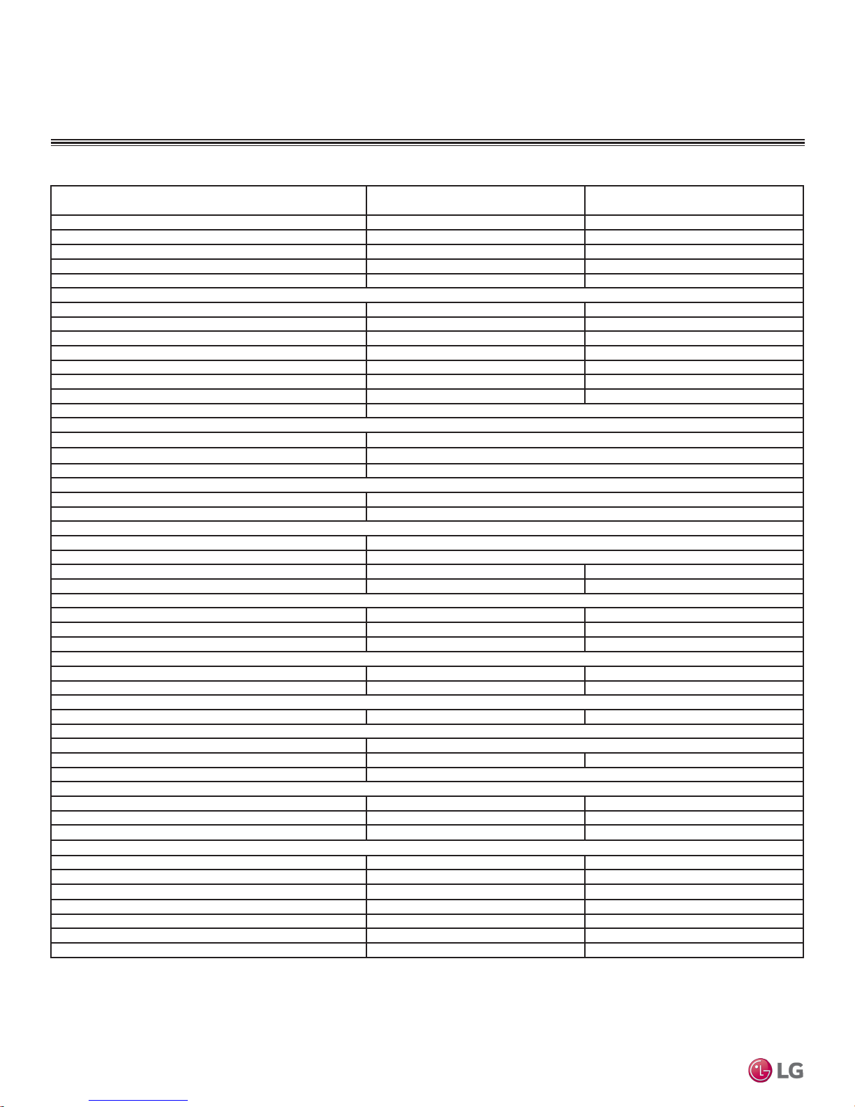
Table 2: Single Zone Vertical Air Handling Unit Specications - continued
System (Model) (Indoor Unit / Outdoor Unit)
Cooling Capacity1 (Min/Rated/Max) (Btu/h) 17,000 ~ 42,000 ~ 48,000 18,000 ~ 48,000 ~ 53,000
Cooling Power Input
Heating Capacity (Min/Rated/Max) (Btu/h) 18,000 ~ 47,000 ~ 55,000 19,000 ~ 56,000 ~ 60,000
Heating Power Input
COP (OD 47°F) 3.44 3.22
Maximum Heating Capacity (Btu/h)
Outdoor 17°F (WB)/Indoor 70°F (DB) 37,000 40,000
Outdoor 5°F (WB)/Indoor 70°F (DB) 32,000 34,000
Power Input [W] @ Outdoor 5℉ (WB) 4,800 5,250
Outdoor -4°F (WB)/Indoor 70°F (DB) 24,000 26,000
EER (OD 95°F) 11.05 10.00
SEER 17.0 16.5
HSPF 10.0 9.5
Power Supply V, Ø, Hz
Outdoor Unit Operating Range
Cooling (°F DB) 5 - 118
Optional Wind Baffle _ Cooling(°F DB) Yes (-4)
Heating (°F WB) -4 - 64
Indoor Unit Operating Range
Cooling (°F WB) 57-77
Heating (°F DB) 59-81
Unit Data
Refrigerant Type
Refrigerant Control EEV
IDU Sound Pressure Level dB(A) (H/M/L)
ODU Sound Pressure Level dB(A) (Cool/Heat)
Unit Weight (lbs.)
IDU (Net/Shipping) 165 / 188 165 / 188
ODU (Net/Shipping) 203 / 232 203 / 232
Power Wiring / Communications Cable (No. x AWG)
Compressor
Compressor (Qty.) Twin Rotary (1) Twin Rotary (1)
Compressor Oil PVE PVE
Dehumidification
Pints/Hour 2 2.5
Fan
IDU Type x Qty. Sirocco x 1
ODU Type x Qty. Propeller x 2 Propeller x 2
Motor / Drive Brushless Digitally Controlled/Direct
Airflow Rate
Single Zone Vertical Air Handling Unit Installation Manual
IDU (H / M / L [CFM]) 1,260 / 1,100 / 1,000 1,400 / 1,260 / 1,000
ODU (Max. [CFM]) 1,942 x 2 1,942 x 2
Factory Set (High) External Static Pressure (in.wg)
Piping
Liquid (in.) 3/8 3/8
Vapor (in.) 5/8 5/8
IDU Condensate Drain, Primary & Secondary O.D. (in.) 3/4 FPT 3/4 FPT
Additional Refrigerant Charge (oz./ft.) 0.43 0.43
Pipe Length
7
Piping Length
Max. Elevation Difference (ft.) 98.4 98.4
Cooling capacity rating obtained with air entering the indoor unit at 80ºF dry bulb (DB) and 67ºF wet
bulb (WB) and outdoor ambient conditions of 95ºF dry bulb (DB) and 75ºF wet bulb (WB).
Heating capacity rating obtained with air entering the indoor unit at 70ºF dry bulb (DB) and 59ºF wet
bulb (WB) and outdoor ambient conditions of 47ºF dry bulb (DB) and 43ºF wet bulb (WB).
This data is rated 0 ft above sea level with 24.6 of refrigerant line per indoor unit and a 0 ft level
difference outdoor and indoor units.
This unit comes with a dry nitrogen charge.
1
Power Input is rated at high speed.
2
Power wiring to the ODU is field supplied, solid or stranded, and must comply with the applicable local
and national codes.
10
1
(Min/Rated/Max) (kW) 1.35 ~ 3.80 ~ 5.30 1.40 ~ 4.80 ~ 6.00
1
(Rated) (kW) 1.45 ~ 4.00 ~ 5.65 1.50 ~ 5.10 ~ 6.20
2
208-230/60/1
3
4
5
48 / 45 / 44 49 / 48 / 44
5
(Minimum/ Maximum) (ft.) 6.6/246 6.6/246
7
(no add’l refrigerant, ft.) 24.6 24.6
Due to our policy of continuous product innovation, some specifications may change without notification.
©LG Electronics U.S.A., Inc., Englewood Cliffs, NJ. All rights reserved. “LG” is a registered trademark of LG Corp.
LV420HV
(LVN420HV/LUU428HV)
LV480HV
(LVN480HV/LUU488HV)
R410A
52 / 54 52 / 54
6
3 x 12 / 4 x 18 3 x 12 / 4 x 18
0.3 0.3
3
Low Ambient Wind Baffle Kit allows operation down to 0°F in cooling mode.
4
Take appropriate actions at the end of HVAC equipment life to recover, recycle, reclaim or destroy R410A
refrigerant according to applicable regulations (40 CFR Part 82, Subpart F) under section 608 of CAA.
5
Sound pressure levels are tested in an anechoic chamber under ISO Standard 3745.
6
All power/communication cables from the ODU to the IDU to be minimum 18 AWG, 4-conductor,
stranded, shielded or unshielded (if shielded, must be grounded to the chassis at the ODU only), and
must comply with applicable and national code.
7
Piping lengths are equivalent.
GENERAL DATA
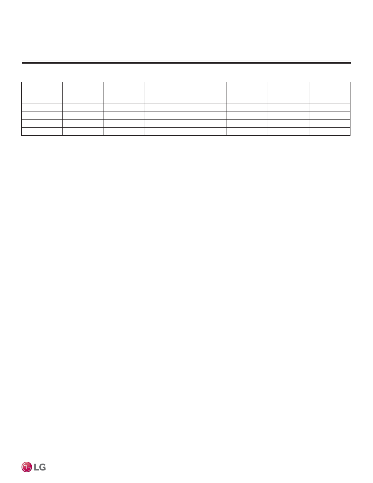
Table 3: Single Zone Vertical Air Handling Unit Electrical Data
Model Number Nominal Tons
Compressor
Qty
LV180HV4 1-1/2 1 13.5/13.5 1 1.6 20 30
LV240HV4 2 1 13.5/13.5 1 1.6 20 30
LV360HV4 3 1 21/21 2 1.6/1.6 32 40
LV420HV 3-1/2 1 21/21 2 1.6/1.6 32 40
LV480HV 4 1 21/21 2 1.6/1.6 32 40
Voltage tolerance is ±10%.
Maximum allowable voltage imbalance is 2%.
MSC = Maximum Starting Current.
Compressor
(A) Cool / Heat
Fan Qty
MCA = Minimum Circuit Ampacity.
Maximum Overcurrent Protection (MOP) is calculated as follows: (Largest motor FLA x 2.25) + (Sum of
other motor FLA) rounded down to the nearest standard fuse size.
Outdoor Unit
Fan (A)
MCA (A) MOP (A)
Electrical
Product Data
Due to our policy of continuous product innovation, some specifications may change without notification.
©LG Electronics U.S.A., Inc., Englewood Cliffs, NJ. All rights reserved. “LG” is a registered trademark of LG Corp.
11
GENERAL INSTALLATION GUIDELINES
DANGER
Location Selection
Selecting the Best Location
• Do not install the unit in an area where combustible gas may generate, flow, stagnate, or leak. These conditions can cause a fire, resulting
in bodily injury or death.
• Do not install the unit in a location where acidic solution and spray (sulfur) are often used as it can cause bodily injury or death.
• Do not use the unit in environments where oil, steam, or sulfuric gas are present as it can cause bodily injury or death.
Install a fence to prevent vermin from crawling into the unit or unauthorized individuals from accessing it. Follow the placement guidelines set forth in
“Clearance Requirements.”
When deciding on a location to place the outdoor unit, be sure to choose an area where run-off water from defrost cycle will not accumulate and
freeze on sidewalks or driveways, which may create unsafe conditions. Properly install and insulate any drain hoses to prevent the hose from freezing, cracking, leaking, and causing unsafe conditions from frozen condensate.
Indoor units (IDUs) must not be placed in an environment where the IDUs may be exposed to harmful volatile organic compounds (VOCs) or in
environments where there is improper air make up or supply or inadequate ventilation. If there are concerns about VOCs in the environment where
the IDUs are installed, proper air make up or supply and/or adequate ventilation must be provided. Additionally, in buildings where IDUs will be
exposed to VOCs consider a factory-applied epoxy coating to the fan coils for each IDU.
Select a location for installing the outdoor unit that will meet the following conditions:
• Where there is enough structural strength to bear the weight of the unit.
• A location that allows for optimum air flow and is easily accessible for inspection, maintenance, and service.
• Where piping between the outdoor unit and indoor unit is within allowable limits.
• Include space for drainage to ensure condensate flows properly out of the unit when it is in heating mode. Avoid placing the outdoor unit in
a low-lying area where water could accumulate.
• If the outdoor unit is installed in a highly humid environment (near an ocean, lake, etc.), ensure that the site is well-ventilated and has a lot
of natural light (Example: Install on a rooftop).
Don’t
• Where it will be subjected to direct thermal radiation from other heat sources, or an area that would expose the outdoor unit to heat or steam
like discharge from boiler stacks, chimneys, steam relief ports, other air conditioning units, kitchen vents, plumbing vents, and other sources
of extreme temperatures.
• Where high-frequency electrical noise / electromagnetic waves will affect operation.
Where operating sound from the unit will disturb inhabitants of surrounding buildings.
Single Zone Vertical Air Handling Unit Installation Manual
• Where the unit will be exposed to direct, strong winds.
• Where the discharge of one outdoor unit will blow into the inlet side of an adjacent unit (when installing multiple outdoor units).
Planning for Snow and Ice
To ensure the outdoor unit operates properly, certain measures are required in locations where there is a possibility of heavy snowfall or
severe wind chill or cold:
1. Prepare for severe winter wind chills and heavy snowfall, even in areas of the country where these are unusual phenomena.
2. Position the outdoor unit so that its airflow fans are not buried by direct, heavy snowfall. If snow piles up and blocks the airflow, the sys-
tem may malfunction.
3. Remove any snow that has accumulated four (4) inches or more on the top of the outdoor unit.
4. In climates that may experience significant snow buildup, mount the outdoor unit on a raised, field-provided platform or stand. The raised
support platform must be high enough to allow the unit to remain above possible snow drifts, and must be higher than the maximum anticipated snowfall for the location.
Due to our policy of continuous product innovation, some specifications may change without notification.
12
©LG Electronics U.S.A., Inc., Englewood Cliffs, NJ. All rights reserved. “LG” is a registered trademark of LG Corp.

GENERAL INSTALLATION GUIDELINES
Location Selection
Planning for Snow and Ice, continued.
5. Design the mounting base to prevent snow accumulation on the platform in front or back of the unit frame.
6. Provide a field fabricated snow protection hood to keep snow and ice and/or drifting snow from accumulating on the coil surfaces.
7. To prevent snow and heavy rain from entering the outdoor unit, install the condenser air inlets and outlets facing away from direct
winds.
8. Consider tie-down requirements in case of high winds or where required by local codes.
When deciding on a location to place the outdoor unit, be sure to choose an area where run-off water from defrost cycle will not accumulate and
freeze on sidewalks or driveways, which may create unsafe conditions. Properly install and insulate any drain hoses to prevent the hose from freezing, cracking, leaking, and causing unsafe conditions from frozen condensate.
Choose an area where run-off water from defrost cycle will not accumulate and freeze on sidewalks or driveways. Properly install and insulate any
drain hoses to prevent the hose from freezing, cracking, leaking, and damaging the outdoor unit.
The indoor unit may take longer to provide heat, or heating performance will be reduced in winter if the unit is installed:
1. In a narrow, shady location.
2. Near a location that has a lot of ground moisture.
3. In a highly humid environment.
4. In an area in which condensate does not drain properly.
General Installation Guidelines
Due to our policy of continuous product innovation, some specifications may change without notification.
©LG Electronics U.S.A., Inc., Englewood Cliffs, NJ. All rights reserved. “LG” is a registered trademark of LG Corp.
13
GENERAL INSTALLATION GUIDELINES
Oceanside Applications
Tie-Downs and Wind Restraints
• The strength of the Single Zone system frame is adequate to be used with field-provided wind restraint tie-downs.
• The strength of the roof must be checked before installing the outdoor units.
• If the installation site is prone to high winds or earthquakes, when installing on the wall or roof, securely anchor the mounting base using a
field-provided tie-down configuration approved by a local professional engineer.
• The overall tie-down configuration must be approved by a local professional engineer. Always refer to local code when using a wind re-
straint system.
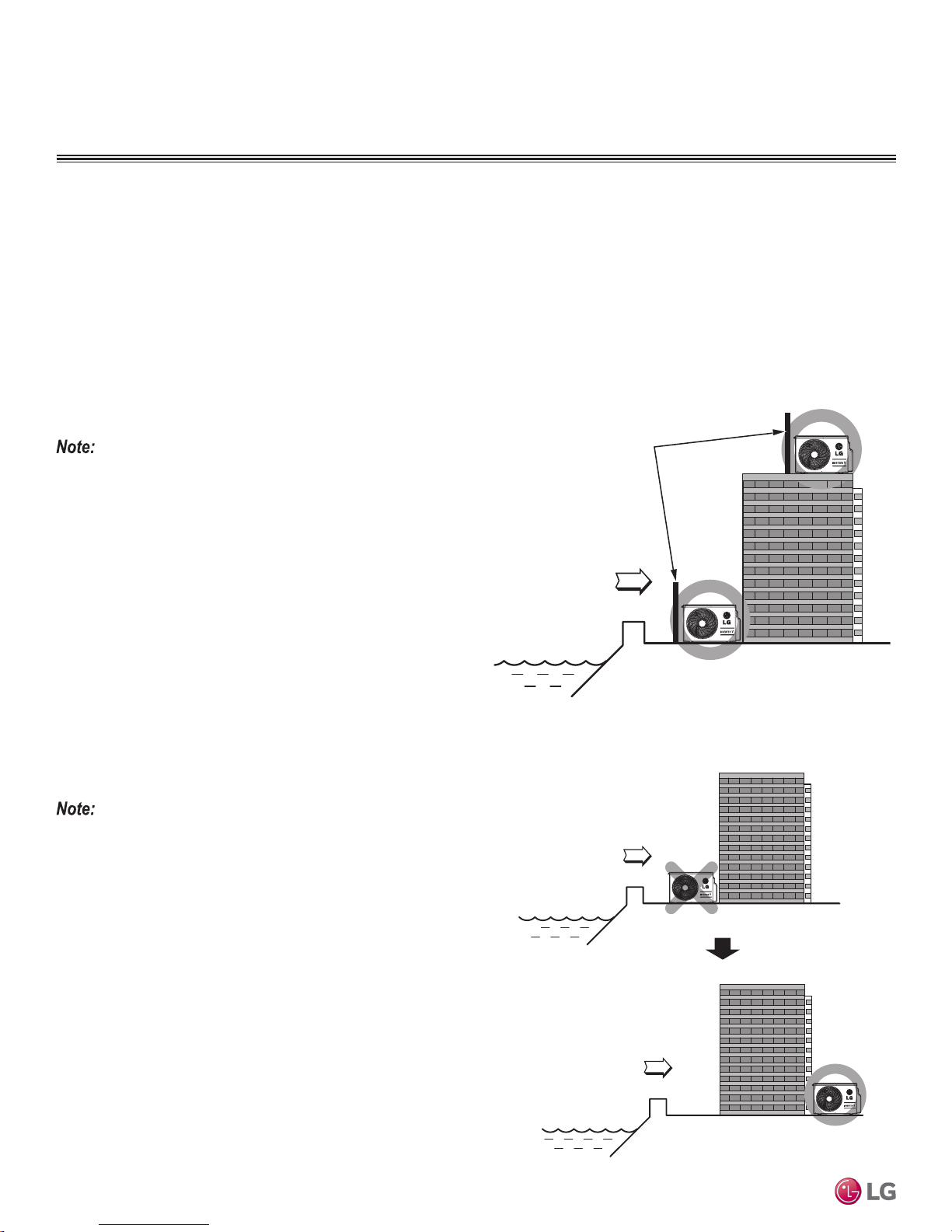
Oceanside Applications
Use of a Windbreak to Shield from Sea Wind
Ocean winds may cause corrosion, particularly on the condenser and
evaporator ns, which, in turn could cause product malfunction or inefcient performance.
• Avoid installing the outdoor unit where it would be directly exposed
to ocean winds.
• Install the outdoor unit on the side of the building opposite from
direct ocean winds.
• Select a location with good drainage.
• Periodically clean dust or salt particles off of the heat exchanger
with water.
• If the outdoor unit must be placed in a location where it would
be subjected to direct ocean winds, install a concrete windbreak
strong enough to block any winds.
• Windbreak must be more than 150% of the outdoor unit’s height.
There must be 2 to 3-1/2 inches of clearance between the outdoor
unit and the windbreaker for purposes of air flow.
Additional anti-corrosion treatment may need to be applied to the outdoor unit at oceanside locations.
Figure 1: Oceanside Placement Using Windbreak.
Windbreak
Sea wind
Figure 2: Placement Using Building as Shield.
Building
Sea wind
Use of a Building to Shield from Sea Wind
Single Zone Vertical Air Handling Unit Installation Manual
If a windbreak is not possible, a building or larger structure must be
used to shield the outdoor unit from direct exposure to the sea wind.
The unit must be placed on the side of the building directly opposite
to the direction of the wind as shown at right.
Due to our policy of continuous product innovation, some specifications may change without notification.
14
©LG Electronics U.S.A., Inc., Englewood Cliffs, NJ. All rights reserved. “LG” is a registered trademark of LG Corp.
Building
Sea wind
GENERAL INSTALLATION GUIDELINES
Case 1
Case 2 Case 3
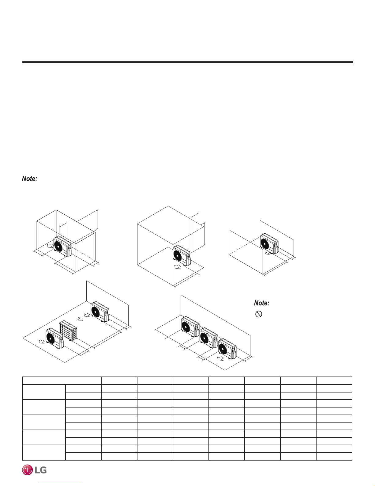
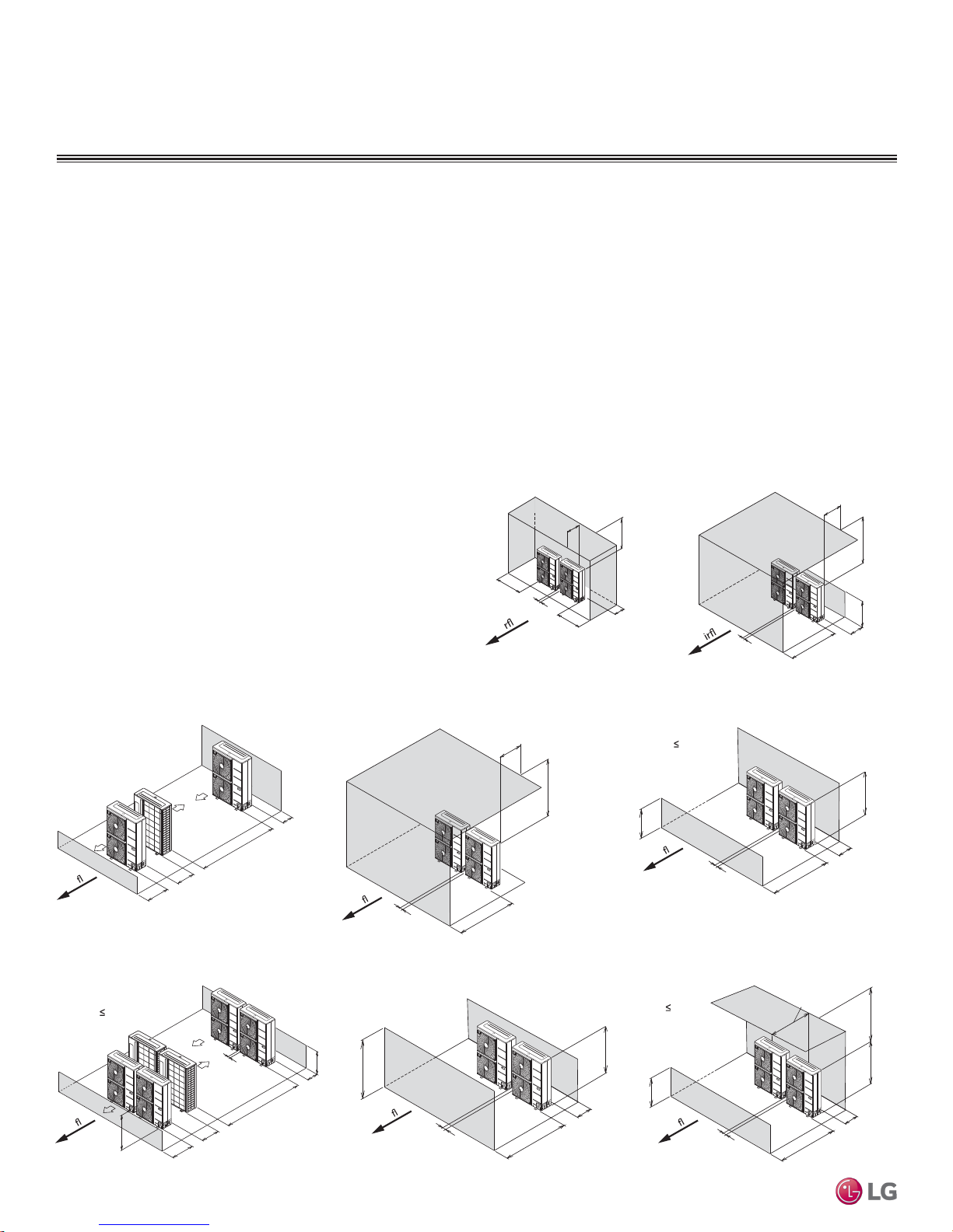
Required Outdoor Unit Clearances
Minimum Clearance Requirements for Single Fan Outdoor Units
Proper clearance for the outdoor unit coil is critical for proper unit operation. When installing the outdoor unit, consider service, inlet and
outlet and minimum allowable space requirements as illustrated in the diagrams below.
Specific clearance requirements in the diagram below are for single fan outdoor units. Figure 3 shows the overall minimum clearances that
must be observed for safe operation and adequate airflow around the outdoor unit.
When placing the outdoor unit under an overhang, awning, sunroof or other “roof-like structure”, observe the clearance requirements (as
shown in Cases 1 and 2 in Figure 3) for height in relation to the unit. This clearance ensures that heat radiation from the condenser is not
restricted around the unit.
Adhere to all clearance requirements if installing the unit on a roof. Be sure to level the unit and ensure that the unit is adequately anchored.
Consult local codes for rooftop mounting requirements. To have successful service access to the outdoor unit, see Figure 3 for minimum
spacing. When installing multiple outdoor units, see Cases 4 and 5 in Figure 3 for correct spacing requirements. Outdoor unit fans draw air
from the back of the unit and discharge out the front. Place units back to back and front to front.
If the outdoor unit is installed between standard and minimum clearances, capacity decreases approximately 10%.
Figure 3: Single Fan Outdoor Unit Service Access and Allowable Clearances Diagram.
General Installation Guidelines
20 inches or less
A
B
Case 4
G
D
F
E
Table 4: Outdoor Unit Service Access and Allowable Clearances Diagram Legend.
Unit: Inch A B C D E F G
Case 1
Case 2
Case 3
Case 4
Case 5
Standard 12 24 - 12 - - Minimum 4 10 - 4 - - 40
Standard - - 20 - - - Minimum - - 14 - - - 40
Standard - - 20 12 - - Minimum - - 14 4 - - Standard - - - 12 24 - Minimum - - - 4 8 79 Standard - 24 - 12 - - Minimum - 10 - 4 - - -
Due to our policy of continuous product innovation, some specifications may change without notification.
©LG Electronics U.S.A., Inc., Englewood Cliffs, NJ. All rights reserved. “LG” is a registered trademark of LG Corp.
1/16 inch
20 inches or less
G
D
C
C
Case 5
Do not place the unit where animals
and/or plants will be in the path of the warm
D
B
B
air, or where the warm air and/or noise will
disturb neighbors.
D
15
GENERAL INSTALLATION GUIDELINES
Min. 59"
Min. 40"
Min. 59"
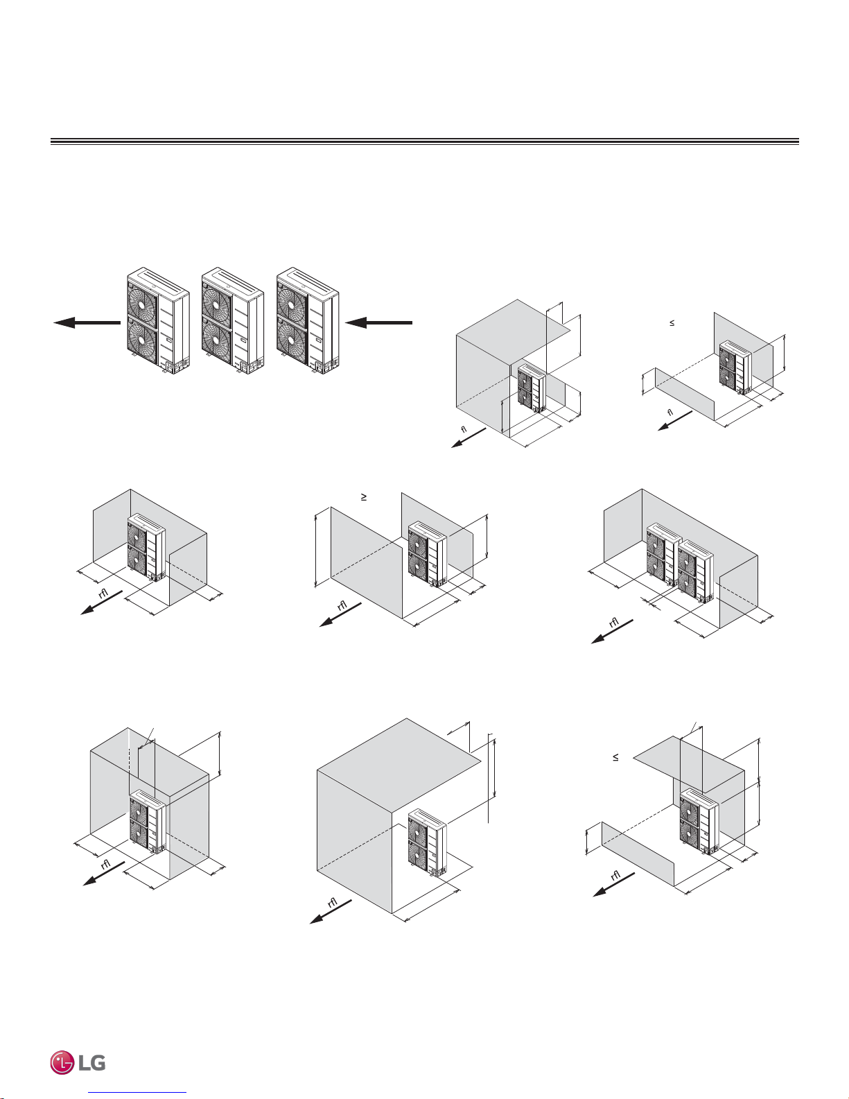
Required Outdoor Unit Clearances
Minimum Clearance Requirements for Dual Fan Outdoor Units
Proper clearance for the outdoor unit coil is critical for proper unit operation. When installing the outdoor unit, consider service, inlet and
outlet and minimum allowable space requirements as illustrated in the diagrams below.
Specific clearance requirements in the diagram below are for dual fan outdoor units. Figure 3 shows the overall minimum clearances that
must be observed for safe operation and adequate airflow around the outdoor unit.
When placing the outdoor unit under an overhang, awning, sunroof or other “roof-like structure”, observe the specified clearance requirements for height in relation to the unit. This clearance ensures that heat radiation from the condenser is not restricted around the unit.
Adhere to all clearance requirements if installing the unit on a roof. Be sure to level the unit and ensure that the unit is adequately anchored.
Consult local codes for rooftop mounting requirements.
To have successful service access to the outdoor unit, see Figure 3 for minimum spacing. When installing multiple outdoor units, refer to the
appropriate clearance diagram for your installation. Outdoor unit fans draw air from the back of the unit and discharge out the front. Place
units back to back and front to front.
Figure 4: Dual Fan Outdoor Unit Service Access
and Allowable Clearances Diagram.
Single Row Units—High Rear Wall and Low Front Wall with
No Side Walls or Overhang
Min. 4"
Min. 79"
w
o
r
i
A
Single Zone Vertical Air Handling Unit Installation Manual
Min. 8"
Min. 40"
Double Row Units—Low Rear and Front Walls with No
Side Walls or Overhang
LR H
Min. 4"
w
o
r
i
A
H
Min. 119"
Min. 24"
Side by Side —High Front Wall with Building Overhang
and No Side or Rear Walls
o
r
i
A
Side by Side—High Front and Rear Walls with No
Side Wall
LR
LF
Min. 12"
w
Min. 4"
LF > H
A
Side by Side—High Rear and Side
Walls with Building Overhang
Max. 20"
Min. 40"
Side by Side—High Rear and Front Walls
with Building Overhang
LR < H
Max. 20"
Min. 40"
Min. 40"
Min. 4"
w
o
i
A
Min. 4"
Max. 20"
Min. 40"
Min. 40"
w
o
r
i
Min 4"
Min. 12"
Min. 12"
w
o
Min. 4"
A
Min. 50"
Side by Side—High Rear Wall and Low Front Wall with
No Side Walls
LF H
LF
w
o
r
i
A
Min 4"
Min. 59"
Side by Side—High Rear Wall and Low Front Wall with
Building Overhang and No Side Walls
LF H
H
LF
w
o
r
i
A
Min 4"
Max. 20"
LR
Min. 12"
H
Min. 12"
Min. 40"
H
Min. 12"
Due to our policy of continuous product innovation, some specifications may change without notification.
16
©LG Electronics U.S.A., Inc., Englewood Cliffs, NJ. All rights reserved. “LG” is a registered trademark of LG Corp.
GENERAL INSTALLATION GUIDELINES
Min. 20"
Required Outdoor Unit Clearances
Figure 4: Dual Fan Outdoor Unit Service Access and Allowable Clearances Diagram - continued
Airflow
Single Unit—High Rear Wall with or
without High Side Walls
Min. 4"
A
i
w
o
Min. 4"
Min. 4"
Single Unit—High Front Wall with Building
Overhand and No Side Walls
Airflow
Single Unit—High Rear and Front Walls with
No Side Walls
LR < H
o
ir
A
LF H
LF
w
o
i
A
Min. 20"
w
H
Min. 4"
Single Unit—High Rear Wall and Low
Front Wall with No Side Walls
Max. 20"
LF H
Min. 40"
LF
H
Min. 40"
LR
Min. 10"
Side by Side—High Rear and Side Walls
w
o
ir
A
Min. 20"
H
Min. 4"
General Installation Guidelines
Min. 40"
Min. 4"
w
o
i
A
Min. 4"
Min. 12"
Single Unit—High Rear and Side Walls with
Building Overhang
Max. 20"
Min. 40"
Min. 6"
A
i
w
o
Min. 4"
Min. 6"
Due to our policy of continuous product innovation, some specifications may change without notification.
©LG Electronics U.S.A., Inc., Englewood Cliffs, NJ. All rights reserved. “LG” is a registered trademark of LG Corp.
Single Unit—High Front and Rear Walls with
Building Overhang and No Side Walls
Max. 20"
w
o
i
A
Min 40"
Single Unit—High Rear Wall and Low Front Wall
with Building Overhang and No Side Walls
Max. 20"
LF H
LF
w
o
i
A
Min. 40"
Min. 12"
Min. 40"
H
17
GENERAL INSTALLATION GUIDELINES
CAUTION
M10
Anchor Bolt
2-3/4~4-23/32
13/16
Unit: Inch
Rigging and Lifting Instructions
Wear protective gloves and safety goggles when handling equipment. Sharp edges may cause personal injury.
Dispose of the packing materials safely.
• Packing materials, such as nails and other metal or wooden parts, may cause puncture wounds or other injuries.
• Tear apart and throw away plastic packaging bags so that children may not play with them and risk suffocation and death.
Be very careful when transporting the product. There is a risk of the product falling and causing physical injury.
• Use appropriate moving equipment to transport each frame; ensure the equipment is capable of supporting the weights listed.
• Some products use polypropylene bands for packaging. Do not use polypropylene bands to lift the unit.
• Support the outdoor unit at a minimum of four points to avoid slippage from rigging apparatus.
• Make sure the outdoor unit is in its original packaging to avoid damage during local transport.
• At the time of delivery, the package must be checked for any damage (exterior and interior). Report any damage to the carrier claims
agent immediately.
• Handle the outdoor unit with care. Keep the outdoor unit upright to avoid damaging inside components.
• If a forklift is to transport the outdoor unit, the forklift arms must pass through the openings at the bottom.
• If a crane is to suspend the outdoor unit, it is recommended that two (2) ropes at least twenty-three (23) feet in length be used. Pass
the ropes under the unit. Pass the rope through the two (2) forklift slots each at the front and rear of the outdoor unit.
• To prevent damage to the outdoor unit, always lift the unit with the ropes attached at four (4) points at an angle of ≤40°.
• Always include padding to protect the outdoor unit from rope damage, and take into consideration the outdoor unit’s center of gravity.
Concrete Platform Specifications
• Concrete foundations must be made of one part cement, two parts sand, and four parts gravel.
• The surface of the foundation must be finished with mortar with rounded edges, and weatherproofed.
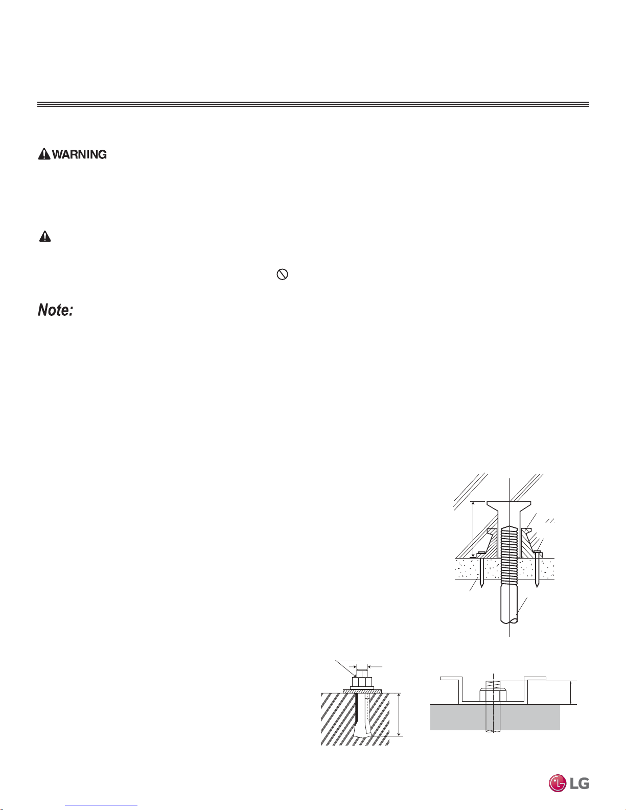
Anchoring the Outdoor Unit
• Tightly anchor the outdoor unit with a bolt and nut to a concrete or rigid platform.
• When installing on a wall (with field-supplied brackets), roof, or rooftop, securely anchor the
mounting platform with nails, taking into consideration the possibility of strong winds or earthquakes.
Single Zone Vertical Air Handling Unit Installation Manual
• If there is a possibility of vibration from the outdoor unit transmitting to the building, add an
anti-vibration material to the platform.
Figure 6: Close up of Bolt Attachment.
Figure 5: Example of Using an Insert for
a Hole in a Reinforced Concrete Beam.
Polyblock /
Anti-Vibration
Material
Insert
Concrete Beam
Nail Securing
Polyblock
Suspension Bolt
18
Due to our policy of continuous product innovation, some specifications may change without notification.
©LG Electronics U.S.A., Inc., Englewood Cliffs, NJ. All rights reserved. “LG” is a registered trademark of LG Corp.
GENERAL INSTALLATION GUIDELINES
Bolt
Refrigerant Pipe
Connection Location
Top of Outdoor Unit
(Looking Down)
Bolt
Bolt
Bolt
Minimum
8
7-7/8
15-3/4
Minimum 24-13/32
Unit: Inch
Minimum
3-15/16)
21-1/2
Minimum 14-9/16
Unit: Inch
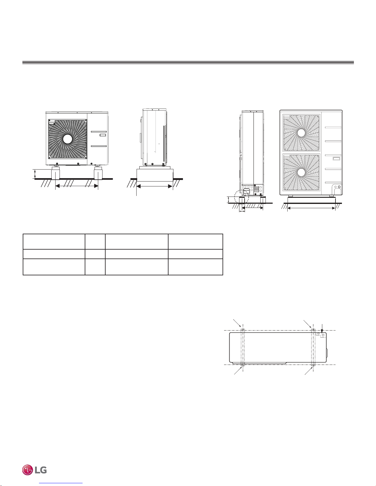
Outdoor Unit Platform Requirements
Outdoor Unit Foundation Requirements.
Figure 7: LUU188HV and LUU248HV Outdoor Units.
Table 5: Outdoor Unit Foundation Specications.
Outdoor Unit Type
Bolt
Type
Concrete Height Bolt Depth
LUU188HV, LUU248HV M10-J Minimum 4 inches Minimum 3 inches
LUU368HV, LUU428HV,
LUU488HV
M10-J Minimum 8 inches Minimum 3 inches
Figure 8: LMU368HV, LMU428HV, LMU488HV Outdoor Units.
General Installation Guidelines
Bolting the Outdoor Unit to the Platform
1. Ensure that the concrete platform will not degrade easily, and has enough
strength to bear the weight of the unit.
2. Include an H-beam support. Firmly attach the corners, otherwise the support
will bend.
3. Use a hexagon nut.
4. Use anti-vibration material.
5. Include enough space around the concrete foundation for condensate
drainage.
6. Seal all wiring and piping access holes to prevent insects from entering the
unit.
Due to our policy of continuous product innovation, some specifications may change without notification.
©LG Electronics U.S.A., Inc., Englewood Cliffs, NJ. All rights reserved. “LG” is a registered trademark of LG Corp.
Figure 9: Bolting the Outdoor Unit to the Platform (Piping
Location May Differ Depending on Outdoor Unit Model).
19
GENERAL INSTALLATION GUIDELINES
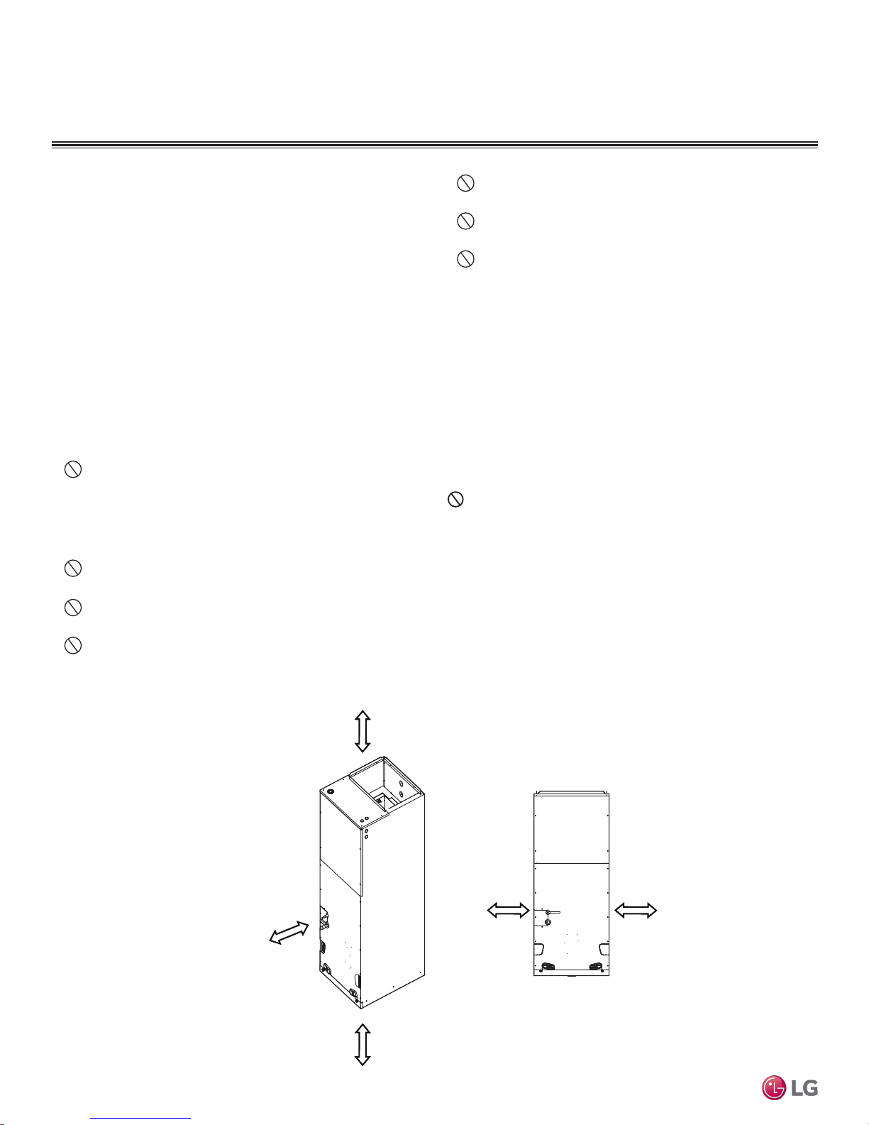
Required Indoor Unit Clearances
Indoor Unit Clearances
Follow recommended best practices when choosing an indoor location for the single zone indoor unit.
• Where there is enough structural strength to bear the weight of the
unit.
• Operating sound from the unit will not disturb occupants.
• Include enough space for service access.
• Include space for drainage to ensure condensate flows properly out
of the unit when it is in cooling mode.
• Use a level indicator to ensure the unit is installed on a level plane.
• Include space for drainage to ensure condensate flows properly out
of the unit when it is in cooling mode
Note:
The unit may be damaged, may malfunction, and/or will not operate as
designed if installed in any of these conditions:
Do not install the unit near a heat or steam source, or where
considerable amounts of oil, iron powder, or flour are used. These
materials may generate condensate, cause a reduction in heat
exchanger efficiency, or malfunction of the condensate drain. If
this is a potential problem, install a ventilation fan large enough to
vent out these materials
Do not install the unit where it will be subjected to direct thermal radiation from other heat sources.
Do not install the unit in an area where combustible gas may
generate, flow, stagnate, or leak. There is the possibility of fire.
Do not install the unit in a location where acidic solution and
spray (sulfur) are often used.
Do not use the unit in environments where oil, steam, or
sulfuric gas are present.
Do not install additional ventilation products on the chassis of
the unit.
Do not install the unit near high-frequency generator sources.
Installing in an Area Exposed to Unconditioned Air
In some installation applications, areas (floors, walls) in some rooms
may be exposed to unconditioned air. The room may be above or
next to an unheated garage or storeroom. To counter
this condition:
• Verify that carpet is or will be installed (carpet may increase
the temperature by three (3) degrees.
• Install radiant heat or another type of heating system to
the floor.
• Add insulation between the floor joists.
Volatile Organic Compounds
Indoor Units (IDUs) must not be placed in an environment where
the IDUs may be exposed to harmful volatile organic compounds
(VOCs) or in environments where there is improper air make up or
supply or inadequate ventilation. If there are concerns about VOCs
in the environment where the IDUs are installed, proper air make up
or supply and/ or adequate ventilation must be provided. Additionally, in buildings where IDUs will be exposed to VOCs consider a
factory-applied epoxy coating to the fan coils for each IDU.
Figure 10: VAHU Indoor Unit Installation Clearances.
More than
13-25/32
Single Zone Vertical Air Handling Unit Installation Manual
More than 23-5/8
clearance from
access panels
for Service
More than
Unit : inch
20
13-25/32
Due to our policy of continuous product innovation, some specifications may change without notification.
©LG Electronics U.S.A., Inc., Englewood Cliffs, NJ. All rights reserved. “LG” is a registered trademark of LG Corp.
0 (zero) 0 (zero)
GENERAL INSTALLATION GUIDELINES
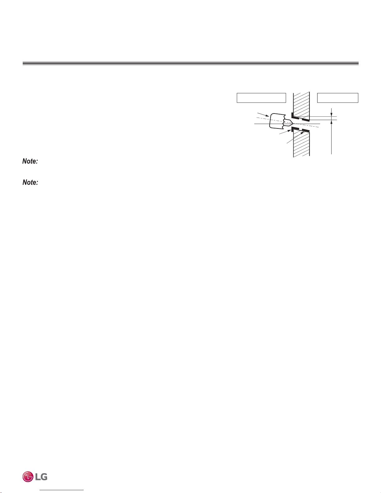
(3/16"~5/16")
Drilling the Piping Hole in the Wall
Follow all piping clearance recommendations.
1. Using a 2-5/8” hole core drill bit, drill a hole at the selected location. Avoid
obstructions in the wall such as electrical wires or conduits and water or gas
pipes.
• The slant of the hole must be 3/16” to 5/16” from level with the slant being
upward on the indoor unit side and downward on the outdoor unit side.
2. Finish off the newly drilled hole as shown with bushing and sleeve covering.
• Sleeve and bushing prevents damage to the tubing/bundling of the piping.
See Refrigerant Piping Connections for Indoor Unit for information on piping installation.
• Go to the Refrigerant Piping Connections section of this manual for information on
indoor unit piping connection installation.
• Go to the Electrical Connections section of this manual for information on conduit /
electrical wiring to the indoor unit.
Figure 11: Drilling Piping Hole.
Indoor
Core Drill
Bushing
Sleeve
WALL
Outdoor
General Installation Guidelines
Due to our policy of continuous product innovation, some specifications may change without notification.
©LG Electronics U.S.A., Inc., Englewood Cliffs, NJ. All rights reserved. “LG” is a registered trademark of LG Corp.
21
 Loading...