

Page 1
Before installing, operating or adjusting this product,
please read this instruction booklet carefully and completely.
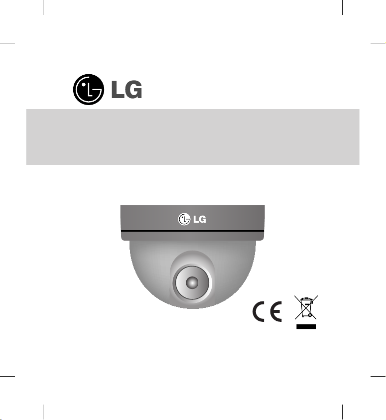
Color Video Camera
Instruction Manual
Models: LV300N-B
LV300P-B
Page 2
2
This lightning flash with arrowhead
symbol within an equilateral triangle is intended to alert the user to
the presence of uninsulated dangerous voltage within the product’s
enclosure that may be of sufficient
magnitude to constitute a risk of
electric shock to persons.
The exclamation point within an
equilateral triangle is intended to
alert the user to the presence of
important operating and maintenance (servicing) instructions in the
literature accompanying the product.
WARNING: Do not install this equipment in a
confined space such as a bookcase or similar
unit.
WARNING: This is a class A product. In a
domestic environment this product may cause
radio interference in which case the user may
be required to take adequate measures.
WARNING: Wiring methods shall be in accordance with the National Electric Code, ANSI/
NFPA 70.
WARNING: To reduce a risk of fire or electric
shock, do not expose this product to rain or
moisture.
CAUTION: The apparatus should not be
exposed to water (dripping or splashing) and no
objects filled with liquids, such as vases, should
be placed on the apparatus.
CAUTION: This installation should be made by
a qualified service person and should conform
to all local codes.
CAUTION: To avoid electrical shock, do not
open the cabinet. Refer servicing to qualified
personnel only.
Disposal of your old appliance
1. When this crossed-out wheeled
bin symbol is attached to a product it means the product is covered by the European Directive
2002/96/EC.
2. All electrical and electronic prod
ucts should be disposed of separately from the municipal waste
stream via designated collection
facilities appointed by the government or the local authorities.
3. The correct disposal of your
old appliance will help prevent
potential negative consequences
for the environment and human
health.
4. For more detailed information
about disposal of your old appliance, please contact your city
office, waste disposal service or
the shop where you purchased
the product.
CAUTION: TO REDUCE THE RISK OF
ELECTRIC SHOCK
DO NOT REMOVE COVER (OR BACK)
NO USER-SERVICEABLE PARTS INSIDE
REFER SERVICING TO QUALIFIED SERVICE
PERSONNEL.
CAUTION
RISK OF ELECTRIC SHOCK
DO NOT OPEN
FCC WARNING: This equipment may
generate or use radio frequency energy.
Changes or modifications to this equip-
ment may cause harmful interference
unless the modifications are expressly
approved in the instruction manual. The
user could lose the authority to operate
this equipment if an unauthorized change
or modification is made.
REGULATORY INFORMATION: FCC
Part 15
This equipment has been tested and
found to comply with the limits for a
Class A digital device, pursuant to Part
15 of the FCC Rules. These limits are
designed to provide reasonable protec-
tion against harmful interference when
the equipment is operated in a com-
mercial environment. This equipment
generates,uses,and can radiate radio
frequency energy and,if not installed and
used in accordance with the instruction
manual,may cause harmful interference
to radio communications. Operation of
this equipment in a residential area is
likely to cause harmful interference in
which case the user will be required
to correct the interference at his own
expense.
• A suitable conduit entries, knock-
outs or glands shall be provided in
the cable entries of this product in
the end user.
Page 3

3
FCC WARNING: This equipment may
generate or use radio frequency energy.
Changes or modifications to this equipment may cause harmful interference
unless the modifications are expressly
approved in the instruction manual. The
user could lose the authority to operate
this equipment if an unauthorized change
or modification is made.
REGULATORY INFORMATION: FCC
Part 15
This equipment has been tested and
found to comply with the limits for a
Class A digital device, pursuant to Part
15 of the FCC Rules. These limits are
designed to provide reasonable protection against harmful interference when
the equipment is operated in a commercial environment. This equipment
generates,uses,and can radiate radio
frequency energy and,if not installed and
used in accordance with the instruction
manual,may cause harmful interference
to radio communications. Operation of
this equipment in a residential area is
likely to cause harmful interference in
which case the user will be required
to correct the interference at his own
expense.
• A suitable conduit entries, knockouts or glands shall be provided in
the cable entries of this product in
the end user.
• Caution: Danger of explosion if
battery is incorrectly replaced.
Replaced only with the same or
equivalent type recommended by
the manufacturer. Dispose of used
batteries according to the manufacturer’s instructions.
• Holes in metal, through which insulated wires pass, shall have smooth
well rounded surfaces or shall be
provided with brushings.
This product is manufactured
to comply with the radio interference requirements of EEC
DIRECTIVE 2004/108/EC
and 2006/95/EC.
Page 4

4
Important Safety Instructions
1. Read these instructions. - All these
safety and operating instructions
should be read before the product is
operated.
2. Keep these instructions. -
The
safety, operating and use instructions
should be retained for future reference.
3. Heed all warnings. -
All warnings
on the product and in the operating
instructions should be adhered to.
4. Follow all instructions. -
All operating and use instructions should be
followed.
5. Do not use this apparatus near
water. - For example: near a bath
tub, wash bowl, kitchen sink, laundry
tub, in a wet basement; near a swimming pool; etc.
6. Clean only with dry cloth. -
Unplug
this product from the wall outlet
before cleaning. Do not use liquid
cleaners.
7. Do not block any ventilation open
ings. Install in accordance with
the manufacturer’s instructions.
- Slots and openings in the cabinet
are provided for ventilation, to ensure
reliable operation of the product, and
to protect it from over- heating. The
openings should never be blocked by
placing the product on a bed, sofa,
rug or other similar surface. This
product should not be placed in a
built-in installation such as a bookcase or rack unless proper ventilation
is provided and the manufacturer’s
instructions have been adhered to.
8. Do not install near any heat sourc
es such as radiators, heat registers, stoves, or other apparatus
(including amplifiers) that produce
heat.
9. Do not defeat the safety purpose
of the polarized or grounding-
type plug. A polarized plug has
two blades with one wider than
the other. A grounding type
plug has two blades and a third
grounding prong. The wide blade
or the third prong are provided
for your safety. If the provided
plug does not fit into your out-
let, consult an electrician for
replacement of the obsolete out-
let.
10. Protect the power cord from
being walked on or pinched par-
ticularly at plugs, convenience
receptacles, and the point where
they exit from the apparatus.
11. Only use attachments/acces
sories specified by the manufac-
turer.
12. Use only the cart, stand, tripod,
bracket, or table specified by the
manufacturer, or sold with appa-
ratus. When a cart is used, use
caution when moving the cart/
apparatus combination to avoid
injury from tip-over.
Important Safety Instructions
Page 5
5
9. Do not defeat the safety purpose
of the polarized or groundingtype plug. A polarized plug has
two blades with one wider than
the other. A grounding type
plug has two blades and a third
grounding prong. The wide blade
or the third prong are provided
for your safety. If the provided
plug does not fit into your outlet, consult an electrician for
replacement of the obsolete outlet.
10. Protect the power cord from
being walked on or pinched particularly at plugs, convenience
receptacles, and the point where
they exit from the apparatus.
11. Only use attachments/acces
sories specified by the manufacturer.
12. Use only the cart, stand, tripod,
bracket, or table specified by the
manufacturer, or sold with apparatus. When a cart is used, use
caution when moving the cart/
apparatus combination to avoid
injury from tip-over.
13. Unplug this apparatus during
lightning storms or when unused
for long periods of time.
14. Refer all servicing to qualified
service personnel. Servicing is
required when the apparatus has
been damaged in any way, such
as power- supply cord or plug is
damaged, liquid has been spilled
or objects have fallen into the
apparatus, the apparatus has
been exposed to rain or moisture, does not operate normally,
or has been dropped.
Important Safety Instructions
Page 6

What's in the box
6
Safety Precautions
Do not attempt to disassemble the camera
To prevent electric shock, do not remove
screws or covers. There are no user
serviceable parts inside. Ask a qualified
service personnel for servicing.
Do not use strong solvents or
detergents
Use a dry cloth to the camera when it is
dirty. If it is hard to remove the dirt on the
camera, use a mild detergent and wipe
it gently.
Before operating, please
check proper temperature,
humidity and power source
ratings.
Use the camera under conditions where
temperature is between -10 °C to +50 °C.
Do not expose the camera in
such conditions as shown
below.
Use in a room or area filled with cigarette
smoke, dust or gas.
Avoid the camera with direct
sunlight
Do not aim the camera at bright objects.
Never face it with direct sunlight or other
extremely bright objects. Otherwise
blooming or smear may be caused.
Handle the camera with care
Do not abuse the camera. Avoid striking,
shaking, etc. The camera could be damaged by improper handling or storage.
Do not expose the camera to
rain or moisture
This product is designed for indoor use
or location where it is protected from
rain and moisture. When exposed to
moisture, turn the power off immediately
and ask a qualified service personnel
for servicing. Moisture can damage the
camera and also create the danger of
electric shock.
Page 7

7
What's in the boxSafety Precautions
Video Cable
Camera Body
M4 Tapping Screws
(2 EA)
(Pan Lock Screw)
Adapter
(DC 12 V, 300 mA)
Optional
Page 8

Front View
Side View
Pan Base
6-pin Dip Switch
Tilt Base
Zoom Lever
Tilting Lock Screw
Focus Lever
Lens
Tilting Lock Screw
Dome Cover Separatory Spring
8
Construction Installation
Camera Installation
1. Aim the LG logo of the Dome Camera to face the place that you wish to
watch.
2. Tighten the M4 Tapping Screws to fix the Dome Camera on the ceiling,
then adjust the Pan(Left/ Right) by moving the Pan Base. Tighten the
M4 Tapping Screws after adjustment.
3. Loosen the Tilting Lock Screw. Adjust the Til
Tilt Base then tighten Tilting Lock Screw.
4.
Set the Zoom Lever to a point between "Tele" and "Wide" to choose the
desired angular field of view.
Set the Focus Lever to a point between "Near" and "Far" to choose the
desired focus of view.
5. Install the Dome Cover to the main body by turning it counterclockwise
to the end.
Notes
• When you install the camera, handle with care. The camera could be damaged by
improper handling or storage.
• If this camera is mounted on the other places except ceiling, you need an extra
bracket for mounting. (not supplied)
Page 9

99
Camera Installation
1. Aim the LG logo of the Dome Camera to face the place that you wish to
watch.
2. Tighten the M4 Tapping Screws to fix the Dome Camera on the ceiling,
then adjust the Pan(Left/ Right) by moving the Pan Base. Tighten the
M4 Tapping Screws after adjustment.
3. Loosen the Tilting Lock Screw. Adjust the Til
t(Up/ Down) by moving the
Tilt Base then tighten Tilting Lock Screw.
4.
Set the Zoom Lever to a point between "Tele" and "Wide" to choose the
desired angular field of view.
Set the Focus Lever to a point between "Near" and "Far" to choose the
desired focus of view.
5. Install the Dome Cover to the main body by turning it counterclockwise
to the end.
Notes
• When you install the camera, handle with care. The camera could be damaged by
improper handling or storage.
• If this camera is mounted on the other places except ceiling, you need an extra
bracket for mounting. (not supplied)
Hole for Fixing
Page 10

10
Installation
Camera Connection
Connect the Power Adapter (12 V, 300 mA; optional) to the Power
Input Jack of the camera as shown below.
Installation
NOTES:
•
When you disassemble the Dome Cover, lift the Dome Cover
Separatory Spring on the opposite side of LG Logo and turn the
Dome Cover clockwise simultaneously.
•
When you install the camera, handle with care. The camera could
be damaged by improper handling or storage.
•
If this camera is mounted on the other places except ceiling, you
need an extra bracket for mounting.(not supplied)
Power Input
Jack
Adapter
Jack
Power Adapter
(Not supplied)
Monitor
BNC
Page 11

11
Installation
NOTES:
•
When you disassemble the Dome Cover, lift the Dome Cover
Separatory Spring on the opposite side of LG Logo and turn the
Dome Cover clockwise simultaneously.
•
When you install the camera, handle with care. The camera could
be damaged by improper handling or storage.
•
If this camera is mounted on the other places except ceiling, you
need an extra bracket for mounting.(not supplied)
Dome Cover
Separatory Spring
Page 12

12
6-pin Dip Switch Setting
This camera has the 6-pin Dip
Switch for setting.
1. ELC / ALC
ELC (Electronic IRIS), ALC
(Auto IRIS)
The default setting is ALC.
2. FL (Flickerless)
Use for removing the flicker of
picture.
The default setting is OFF.
3. AWB/HOLD
AWB (Auto White Balance),
HOLD (White Balance Hold).
The default setting is AWB.
4. BLC
Backlight compensation eliminates strong background light
which makes the camera picture dark such as a spotlight.
You can select the mode for
adjusting the iris lens.
The default setting is OFF.
5. L/L
Line-Lock mode, Internal Mode.
Line-Lock when using AC 24 V
power.
The default setting is INT.
6. AGC (Auto Gain Control)
If the image are too dark,
change the maximum value to
make the image lighter. The
D&N function is activated automatically AGC ON mode.
The default setting is ON.
Setup Troubleshooting
Check the following guide for the
possible cause of a problem before
contacting service.
The picture is poor
Does the Dome Cover have lots of
dust on the surface?
- Use a dry cloth to clean the
camera when it is dirty.
Smear may be caused to the
screen of night than daytime.
- Adjust the Focus by moving the
Focus Lens.
Page 13

13
Check the following guide for the
possible cause of a problem before
contacting service.
The picture is poor
Does the Dome Cover have lots of
dust on the surface?
- Use a dry cloth to clean the
camera when it is dirty.
Smear may be caused to the
screen of night than daytime.
- Adjust the Focus by moving the
Focus Lens.
Contrast of the screen is not
clear.
Check the condition of the monitor.
A light source such as a spot light
causes burn-in on the display
screen. Adjust position or angle
of the camera to eliminate strong
background light.
Background screen appears
white extremely.
You can set the background
compensation to OFF.
Page 14

14
Dimension
91 mm
ø 121.5
ø 100
ø 90
10 mm
31 mm
Specifications
Model LV300N-B LV300P-B
Signal System NTSC PAL
Total / Effective Pixels 410 K / 380 K 470 K / 440 K
Pick-Up Device 6 mm Interline Color CCD (Super HAD)
Lens Vari-Focal Lens (f=4.0 to 9.0 mm/F=1.6)
Iris DC Iris
Signal Process Digital Signal Process (SS11X)
Scanning System 2 : 1 Interlace
Sync. System Internal
Scanning Frequency 59.94 Hz(VD) 50 Hz(VD)
Resolution 520 TV Lines
S/N Ratio More than 48 dB
Standard Illuminance 2 000 lx (3 200 K)
Sensitivity (1/3 output) 0.5 lx (F1.2)
Video Output Signal 1 Vp-p Composite (75 Ω)
Gain Control Auto
Exposure Automatic control with DC Iris motor
Shutter Speed 1/60 to 1/100 000 s 1/50 to 1/100 000 s
White Balance Auto
Back Light Compensation Auto / OFF
Power Source DC 12 V
Power Consumption Less than 2.3 W
Operating Temp. -10 °C to 50 °C (Humidity : 0 % RH to 80 % RH)
Storage Temp. -20 °C to 60 °C (Humidity : 0 % RH to 85 % RH)
Net Weight 270 g
Dimensions ø 121.5 (Diameter) x 91 mm(H)
Page 15

1515
Specifications
Model LV300N-B LV300P-B
Signal System NTSC PAL
Total / Effective Pixels 410 K / 380 K 470 K / 440 K
Pick-Up Device 6 mm Interline Color CCD (Super HAD)
Lens Vari-Focal Lens (f=4.0 to 9.0 mm/F=1.6)
Iris DC Iris
Signal Process Digital Signal Process (SS11X)
Scanning System 2 : 1 Interlace
Sync. System Internal
Scanning Frequency 59.94 Hz(VD) 50 Hz(VD)
Resolution 520 TV Lines
S/N Ratio More than 48 dB
Standard Illuminance 2 000 lx (3 200 K)
Sensitivity (1/3 output) 0.5 lx (F1.2)
Video Output Signal 1 Vp-p Composite (75 Ω)
Gain Control Auto
Exposure Automatic control with DC Iris motor
Shutter Speed 1/60 to 1/100 000 s 1/50 to 1/100 000 s
White Balance Auto
Back Light Compensation Auto / OFF
Power Source DC 12 V
Power Consumption Less than 2.3 W
Operating Temp. -10 °C to 50 °C (Humidity : 0 % RH to 80 % RH)
Storage Temp. -20 °C to 60 °C (Humidity : 0 % RH to 85 % RH)
Net Weight 270 g
Dimensions ø 121.5 (Diameter) x 91 mm(H)
Page 16

P/NO: MFL40426626
 Loading...