

Page 1

MICROWAVE OVEN
SERVICE MANUAL
MODEL: LTRM1240SW
LTRM1240SB
LTRM1240ST
CAUTION
BEFORE SERVICING THE UNIT, READ THE
SAFETY PRECAUTIONS IN THIS MANUAL.
Website http://us.lgservice.com
P/NO : 3828W5S6018
July, 2004
Printed in Korea
Page 2

-1-
This device is to be serviced only by properly qualified service personnel.
Consult the service manual for proper service procedures to assure continued safety operation and for precautions to be taken to
avoid possible exposure to excessive microwave energy.
PRECAUTIONS TO BE OBSERVED BEFORE AND DURING
SERVICING TO AVOID POSSIBLE EXPOSURE TO
EXCESSIVE MICROWAVE ENERGY
A) Do not operate or allow the oven to be operated with the door open.
B) Make the following safety checks on all ovens to be serviced before activating the magnetron or other
microwave source, and make repairs as necessary; (1) interlock operation, (2) proper door closing, (3) seal
and sealing surfaces (arcing, wear, and other damage), (4) damage to or loosening of hinges and latches, (5)
evidence of dropping or abuse.
C) Before turning on microwave power for any service test or inspection within the microwave generating
compartments, check the magnetron, wave guide or transmission line, and cavity for proper alignment,
integrity, and connections.
D) Any defective or misadjusted components in the interlock, monitor, door seal, and microwave generation and
transmission systems shall be repaired, replaced, or adjusted by procedures described in this manual before
the oven is released to the owner.
E) A microwave leakage check to verify compliance with the Federal Performance Standard should be performed
on each oven prior to release to the owner.
SAFETY PRECAUTIONS
CAUTION
MICROWAVE RADIATION
DO NOT BECOME EXPOSED TO RADIATION FROM THE MICROWAVE GENERATOR
OR OTHER PARTS CONDUCTING MICROWAVE ENERGY.
Page 3

-2-
MECHANICAL SERVICE INFORMATION
TABLE OF CONTENTS
1. Safety precautions
......................................................................................................................................
Inside front cover
2. Specifications
..............................................................................................................................................
3
3. Cautions
......................................................................................................................................................
4
4. Installations
.................................................................................................................................................
5
5. Overall Circuit Diagram
...............................................................................................................................
6-7
6. Operating Procedures
.................................................................................................................................
8-9
7. Procedure for Measuring Microwave Energy Leakage
..............................................................................
10-11
8. Disassembly Instructions ............................................................................................................................ 12-15
9. Interlock Continuity Test ............................................................................................................................. 16
10. Test and Checkout Procedures,and Troubleshooting
A. Test Procedures
-----------------------------------------------------------------------------------------------------------------------
17-20
B. Checkout Procedures
----------------------------------------------------------------------------------------------------------------
21-23
C. Troubleshooting
------------------------------------------------------------------------------------------------------------------------
24-29
11. Exploded View
..........................................................................................................................................
30-37
12. Replacement Parts List
.............................................................................................................................
38-44
FOREWORD
Read this Manual carefully. Failure to adhere to or observe the information in this Manual may result in exposing yourself to
the Microwave Energy normally contained within the oven cavity.
Page 4
-3-
This microwave oven is designed for household use only.
It is not recommended for commercial purposes.
DESCRIPTION
LTRM1240SW
LTRM1240SB
LTRM1240ST
120 Volts AC 60 Hz
Single phase, 3 wire grounded
Microwave 1650W
Toast 800W
1200 Watts full microwave power (IEC60705)
2450 MHz
2M214
0 ~ 90 min.
23”(W)x 12 1/2 ”(H)x 17 1/8 ”(D)
14 11/
16 ”(W)x 9
5
/
8 ”(H)x 15
5
/
8 ”(D)
15.9 kg (approx.)
17.3 kg (approx.)
Microwave Power for Variable Cooking
Power level
MAX ...................................... Full power throughout the cooking time
MED.-HIGH ............................ approx. 80% of Full power
MEDIUM ................................ approx. 60% of Full power
DEFROST .............................. approx. 40% of Full power
LOW/WARM ........................... approx. 20% of Full power
TOAST, COMBI
Owner's manual
Glass turntable
Roller rest
ITEM
MODEL
Power Requirement
Power Output
Microwave Frequency
Magnetron
Timer
Outside Dimensions
Cavity Dimensions
Net Weight
Shipping weight
Control Complement
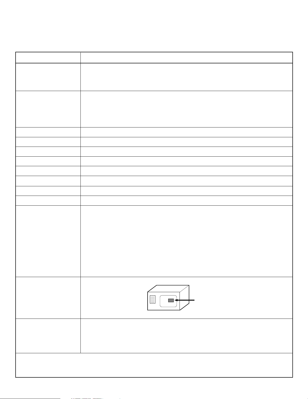
Nameplate Location
Accessories
SPECIFICATIONS
Back Side
Page 5
-4-
• DO NOT operate on a 2-wire extension cord during repair
and use.
• NEVER TOUCH any oven components or wiring during
operation.
• BEFORE TOUCHING any parts of the oven, always remove
the power plug from the outlet.
• For about 30 seconds after the oven stops, an electric
charge remains in the high voltage capacitor. When
replacing or checking, you must discharge the high voltage
capacitor by shorting across the two terminals with an
insulated screwdriver.
•
Remove your watches whenever working close to or
replacing the Magnetron.
• DO NOT touch any parts of the control panel circuit. A
resulting static electric discharge may damage this P.C.B.
• NEVER operate the oven with no load.
• NEVER injure the door seal and front plate of the oven
cavity.
• NEVER put iron tools on the magnetron.
• NEVER put anything into the latch hole and the interlock
switches area.
• Proper operation of the microwave oven requires that the
magnetron be assembled to the waveguide and cavity.
Never operate the magnetron unless it is properly installed.
• Be sure that the magnetron gasket is properly installed
around the dome of the tube whenever installing the
magnetron.
CAUTIONS
Unlike other appliances, the microwave oven is
high-voltage and high-current equipment.
Though it is free from danger in ordinary use,
extreme care should be taken during repair.
THE OVEN IS TO BE SERVICED ONLY BY
PROPERLY QUALIFIED SERVICE
PERSONNEL.
MICROWAVE RADIATION
Personnel should not be exposed to the microwave
energy which may radiate from the magnetron or
other microwave generating device if it is improperly
used or connection.
All input and output microwave connections,
waveguide, flange and gasket must be secure
never operate the device without a microwave
energy absorbing load attached.
Never look into an open waveguide or antenna
while the device is energized.
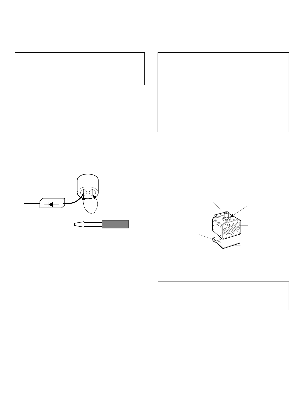
Gasket
ANTENNA
COOLING FIN
MAGNETRON
CHASSIS GROUND
FILAMENT
TERMINALS
MAGNETRON
Page 6
-5-
INSTALLATIONS
INSTALLING
1. Empty the microwave oven and clean inside it with a
soft, damp cloth. Check for damage such as misaligned
door, damage around the door or dents inside the cavity
or on the exterior.
2. Put the oven on a counter, table, or shelf that is strong
enough to hold the oven and the food and utensils you
put in it. (The control panel side of the oven is the heavy
side. Use care when handling.)
3. Do not block the vent and the air intake openings.
Blocking vent or air intake openings can cause damage
to the oven and poor cooking results. Make sure the
microwave oven legs are in place to ensure proper air
flow.
4. The oven should not be installed in any area where heat
and steam are generated, because they may damage
the electronic or mechanical parts of the unit.
Do not install the oven next to a conventional surface
unit or above a conventional wall oven.
5. Use microwave oven in an ambient temperature less
than 104°F(40°C).
6. Place the microwave oven on a sturdy and flat surface
at least 10 cm(4 inches) from the wall.
7. Place the microwave oven as far away as possible from
TV, RADIO, COMPUTER, etc., to prevent interference.
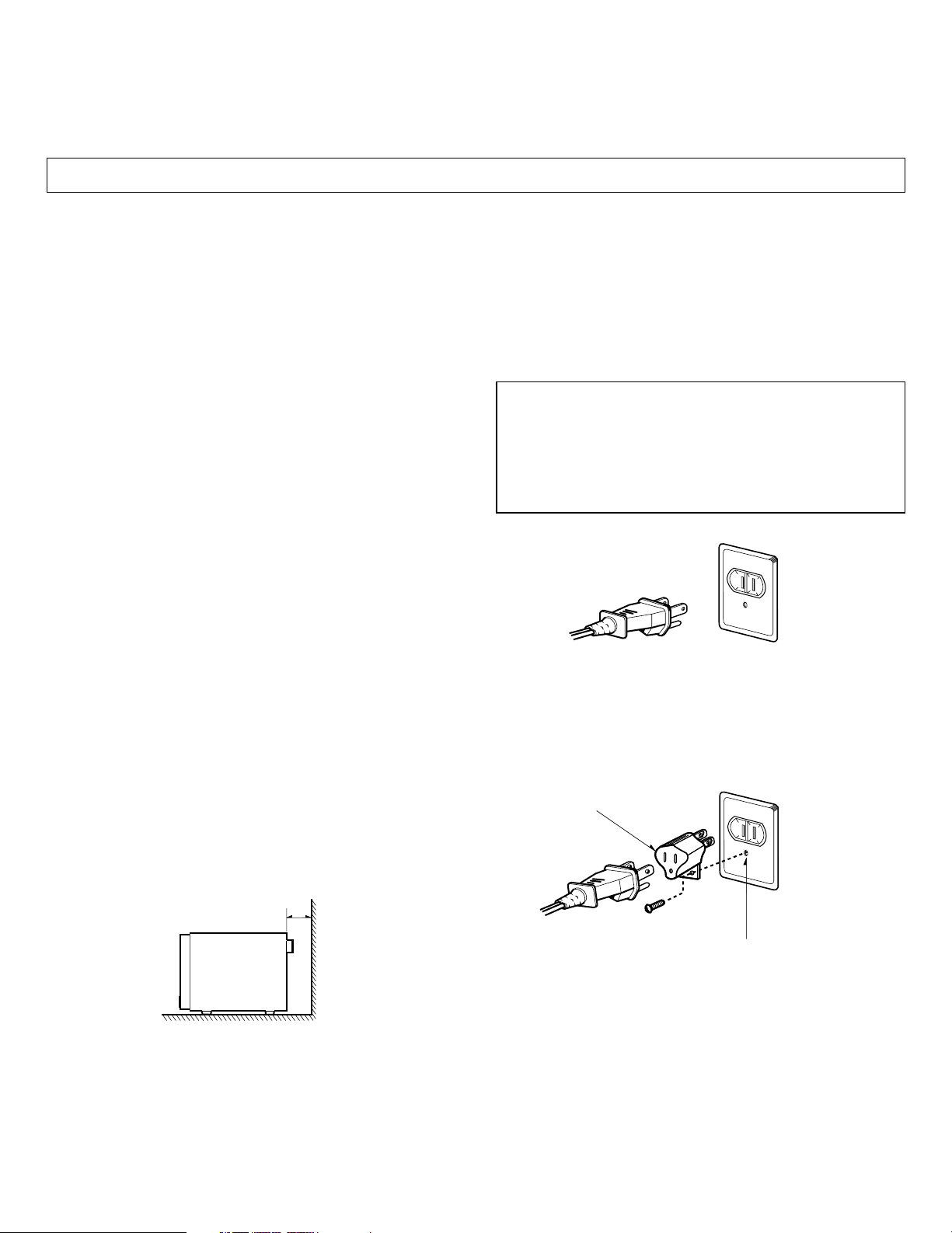
GROUNDING INSTRUCTIONS
For personal safety, this appliance must be fully grounded
at all times.
In the event of an electrical short circuit, grounding reduces
the risk of electrical shock.
The plug must be plugged into an outlet that is properly
installed and grounded.
BEFORE YOU BEGIN, READ THE FOLLOWING INSTRUCTIONS COMPLETELY AND CAREFULLY.
WARNING
Improper use of the grounding plug can result in a risk
of electric shock.
Do not, under any circumstances, cut or remove the
third ground prong from the power cord plug.
PREFERRED METHOD
ENSURE PROPER GROUND
EXISTS BEFORE USE
TEMPORARY METHOD
(ADAPTER PLUGS NOT
PERMITTED IN CANADA)
ALIGN LARGE
PRONGS/SLOTS
ENSURE PROPER GROUND
AND FIRM CONNECTION
BEFORE USE
10cm
Page 7
-6-
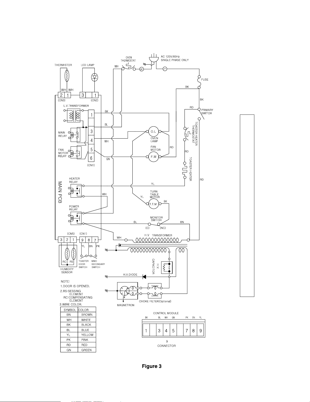
6. OVERALL CIRCUIT DIAGRAM
A. SCHEMATIC DIAGRAM
SERUTAEF LAICEPS ETAROPROCNI MARGAID CITAM
E
HCS S
I
H
T
N
O
SAERA
DEDAH
S
EHT :ET
O
N YTEFAS TNATR
OP
M
I
D
NA
,K
CO
HS
L
A
CIRTCELE
,
ER
I
F
,N
O
I
TA
ID
A
R
EV
AWO
R
C
I
M
M
O
R
F
N
O
I
TCET
ORP
ROF TNATROP
MI
AP
DE
I
F
I
CEPS S
’
R
ER
U
T
CA
F
U
N
AM
Y
LNO TA
H
T
LA
I
T
NESSE
SI
T
I
G
NI
CI
VRES
NE
HW
.S
DRAZA
H
S
T
R
GAID CITAMEHCS EHT FO SAERA DEDAHS EHT NI STNENOPMO
C
LA
C
I
T
IRC EHT R
O
F
DESU
E
B
.MAR
DNA STNENOPMOC FO SEULAV EHT ,MARGAID CITAMEHCS CISAB SI SIHT ECNIS :ECITON
.TNEMEVORPMI ROF EGNAHC OT TCEJBUS
E
RA SNOITCENNOC LAITRAP EMOS
Page 8
-7-
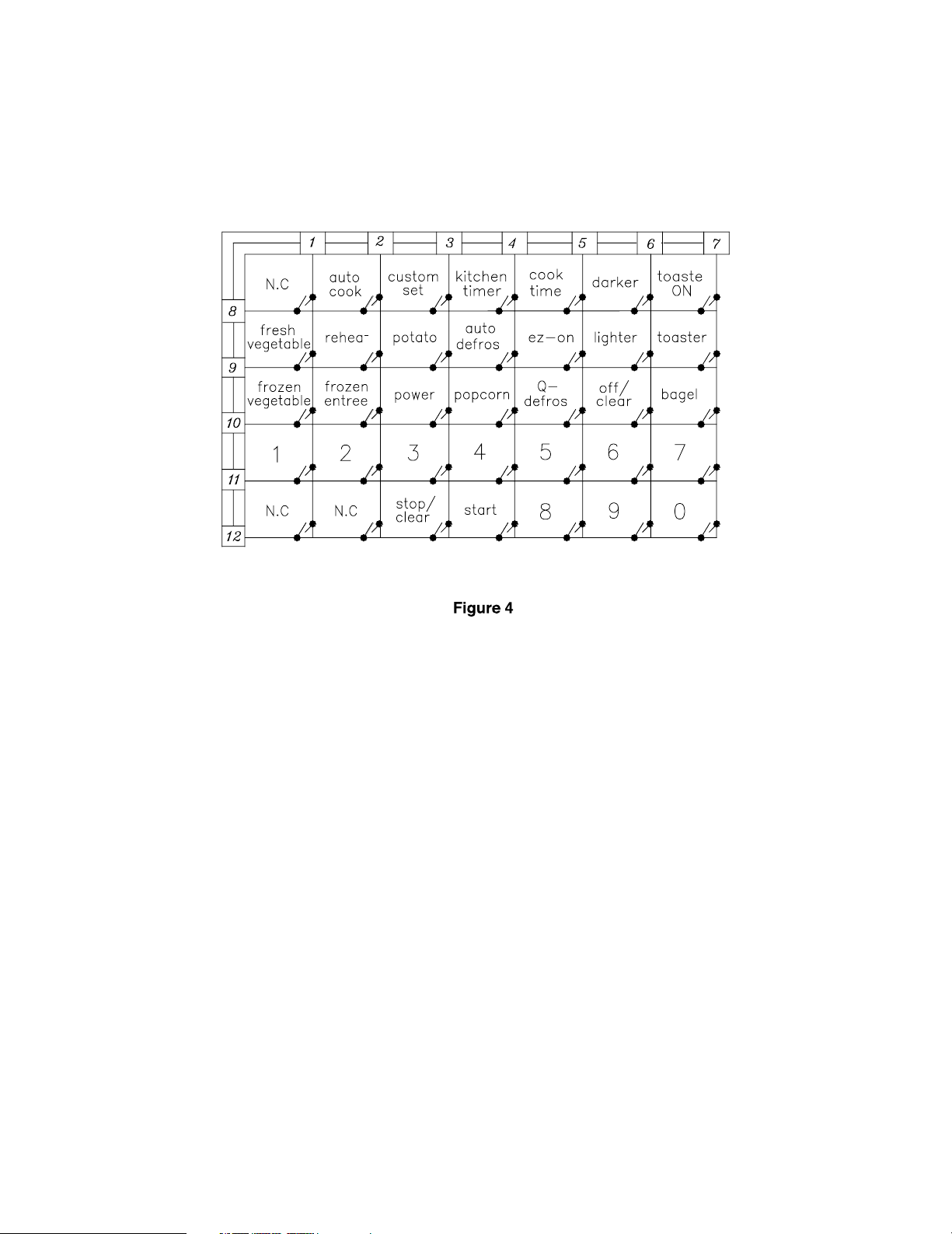
B. MATRIX CIRCUIT FOR TOUCH KEY BOARD
Page 9
-8-
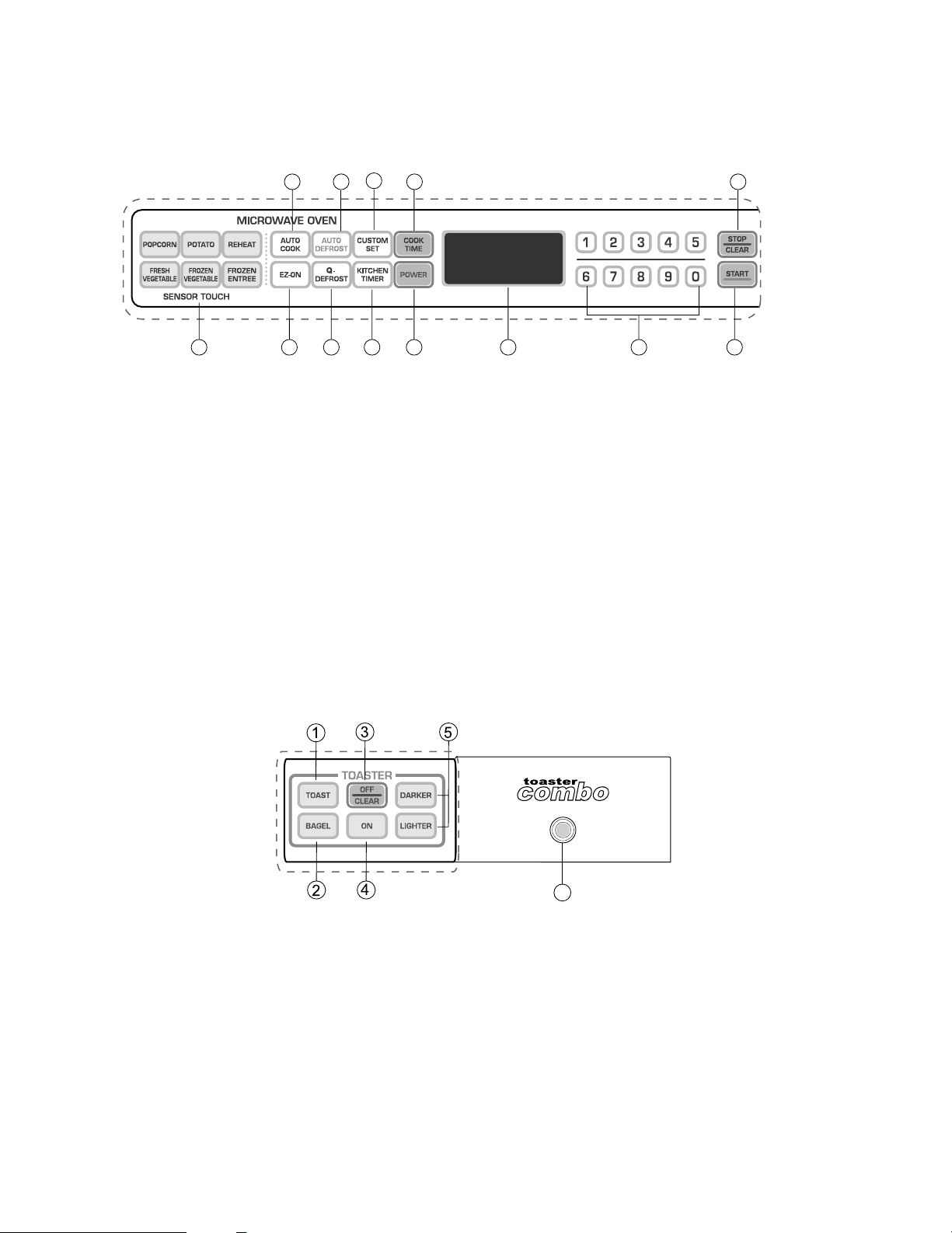
7. OPERATING PROCEDURES
A. OVEN CONTROL PANEL
MICROWAVE CONTROL AREA
1. DISPLAY. The Display includes a clock and indicators that tell you time of day, cooking time settings, and cooking
functions selected.
2. STOP/CLEAR. Touch this pad to stop the oven or clear entries.
3. START. Touch this pad to start all entries (except the Auto Cook and Add Minute function which start automatically)
and to turn Child Lock on or off.
4. AUTO COOK. Touch this pad to select programming food items.
5. EZ-ON. Touch this pad to cook at 100% cook power for 1 minute to 99 minutes 59 seconds.
6. AUTO DEFROST. This pad is an accurate defrosting method for frozen meat, poultry and fish up to 6.0 lbs.
7. Q-DEFROST. This pad provides you with the quick defrosting method for 1.0 pound frozen foods.
8. CUSTOM SET. Touch this pad to change the oven's default settings for sound, clock, scroll speed and Lbs/Kg.
9. KITCHEN TIMER. Touch this pad to use your microwave oven as a kitchen timer.
10. COOK TIME. Touch this pad to set a cooking time.
11. POWER. Touch this pad to set a cooking power.
12. NUMBER PADS. Touch Number Pads to enter cooking time, power level, quantities, or weights.
13. SENSORTOUCH. This pad allows you to cook most of your favorite foods without having to select cooking times and
power levels.
TOASTER CONTROL AREA
1. Toast. Toast bread
2. Bagel. Toasts Bagels
3. Off/Clear. Touch this pad to stop the toaster or clear entries.
4. On. Touch this pad to start the toasting process.
5. Darkness Control. Adjust darkness control to desired setting before cooking foods.
(Default : 5, "1" is the lightest and "9" is the darkest)
6. Indicator Light. When operating toaster with door closed, this will be illuminated. If you open the door during
toasting, this will blink.
6
24 6 8 10
13 5 7 9 11 1 12 3
Page 10

B. EASY USE TABLE
MICROWAVE OVEN
(1) KITCHEN TIMER
1. Touch STOP/CLEAR.
2. Touch KITCHEN TIMER.
3. Touch correct number for time.
4. Touch START.
(2) CHILD LOCK
To set:
1. Touch STOP/CLEAR.
2. Touch “START” more than 4 seconds.
To cancel:
1. Touch STOP/CLEAR.
2. Touch “START” more than 4 seconds.
(3) AUTO COOK
1. Touch STOP/CLEAR.
2. Touch AUTO COOK Category.
3. Touch START.
(Although you don’t touch start, it will start after
4 seconds automatically)
(4) EZ-ON
1. Touch STOP/CLEAR.
2. Touch EZ-ON
(5) AUTO DEFROST
1. Touch STOP/CLEAR.
2. Touch AUTO DEFROST.
Three different defrosting levels are provided.
(Touch 1 : Meat
Touch 2 : Poultry
Touch 3 : Fish)
3. Enter the weight of your food in decimal
increments from 0.1 to 6.0 pounds.
4. Touch START
5. At beeping, turn food over by following the
instructions in the manual.
6. After turning food over, touch START to resume
defrosting.
(6) TIMED COOKING
1. Touch STOP/CLEAR.
2. Touch COOK TIME.
3. Touch number for cooking time.
4. Touch POWER.
5. Touch number for cooking power level.
6. Touch START.
(7) MULTI-STAGE COOKING
1. Touch STOP/CLEAR.
2. Touch COOK TIME.
3. Touch number for cooking time.
4. Touch POWER.
5. Touch number for cooking power level.
6. Repeat steps 2-5 to set 2nd cooking stage.
7. Touch START.
TOASTER
(1) TOAST
1. Touch STOP/CLEAR.
2. Touch TOAST.
3. Touch Darkness Control (1~9 step)
4. Touch START.
(2) BAGEL
1. Touch STOP/CLEAR.
2. Touch BAGEL.
3. Touch Darkness Control (1~9 step)
4. Touch START.
(3) DARKNESS SETTINGS
-9-
Degree of darkness Select darkness level
Light 1~3
Medium 4~6
Dark 7~9
Page 11
8. PROCEDURE FOR MEASURING MICROWAVE
ENERGY LEAKAGE
A. CAUTIONS
(1) Be sure to check a microwave emission prior to servicing
the oven if the oven is operative prior to servicing.
(2) The service personnel should inform the manufacturer,
importer, or assembler of any certified oven unit found to
have a microwave emission level in excess of
5mW/cm.sq. and should repair any unit found to have
excessive emission levels at no cost to the owner and
should ascertain the cause of the excessive leakage.
The service personnel should instruct the owner not to
use the unit until the oven has been brought into
compliance.
(3) If the oven operates with the door open, the service
personnel should;
- Tell the user not to operate the oven
- Contact the manufacturer and CDRH (Center for
Devices and Radiological Health) immediately.
NOTE: Address on CDRH
Office of Compliance (HFZ-312)
Center for Devices and Radiological Health
1390 Piccard Drive
Rockville, Maryland 20850
(4) The service personnel should check all surface and vent
openings for microwave emission testing.
(5) Check for microwave energy leakage after every
servicing. The power density of the microwave radiation
leakage emitted by the microwave oven should not
exceed 1mW/cm.sq. And always start measuring of an
unknown field to assure safety for operating personnel
from radiation leakage.
NOTE: The standard is 5mW/cm.sq. while in the
customer’s home. 1mW/cm.sq. stated here is
manufacturer’s own voluntary standard for units in
customer’s home.
EQUIPMENT
• Electromagnetic energy leakage monitor (NARDA 8100B,
HOLADAY HI 1501)
• 600cc glass beaker
• Glass thermometer 1000C
B. MEASURING MICROWAVE ENERGY LEAKAGE
(1) Pour 275±15cc of 20±5 °C water in a beaker which is
graduated to 600 cc, and place the beaker in the center
of the oven.
(2) Set the energy leakage monitor to 2450 MHz and use it
following the manufacturer’s recommended test
procedure to assure correct result.
(3) When measuring the leakage, always use the 2 inch
(5cm) spacer supplied with the probe.
(4) Operate the oven at its maximum output.
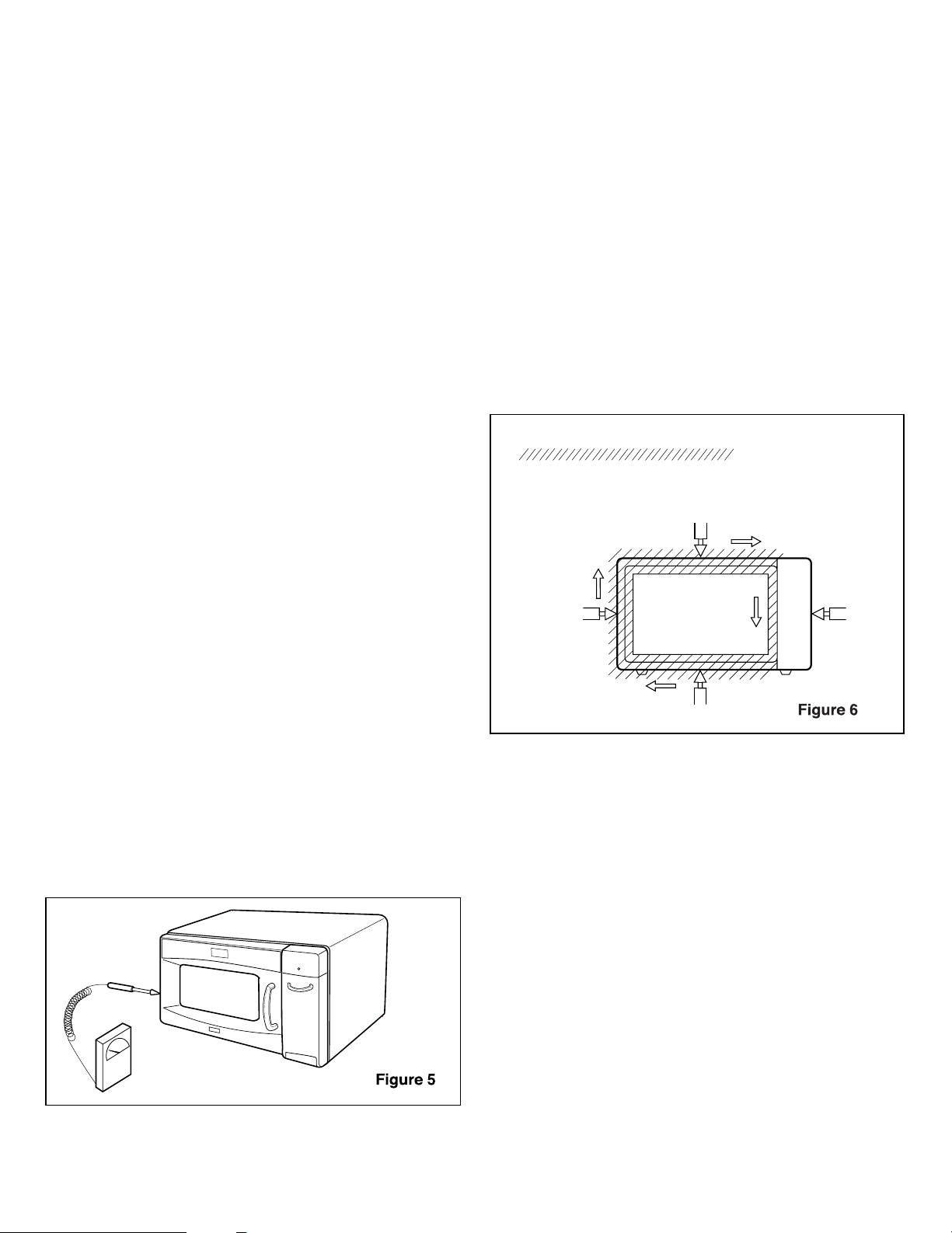
(5) Measure the microwave radiation using and
electromagnetic radiation monitor by holding the probe
perpendicular to the surface being measured. (See
Figure 6)
Move probe along shaded area.
Probe scanning speed
less than 2.5 cm/sec.
C. MEASUREMENT WITH THE OUTER CASE REMOVED
(1) When you replace the magnetron, measure for
microwave energy leakage before the outer case is
installed and after all necessary components are
replaced or adjusted. Special care should be taken in
measuring the following parts.
- Around the magnetron
- The waveguide
WARNING: AVOID CONTACTING ANY HIGH VOLTAGE
PARTS.
-10-
Page 12
D. MEASUREMENT WITH A FULLY ASSEMBLED OVEN
(1) After all components, including the outer panels, are
fully assembled, measure for microwave energy
leakage around the door viewing window, the exhaust
opening and air inlet openings.
(2) Microwave energy leakage must not exceed the values
prescribed below.
NOTES:
Leakage with the outer panels removed - less than
5mW/cm.sq. Leakage for a fully assembled oven
(Before the latch switch (primary) is interrupted) with the
door in a slightly opened position - less than
1 mW/cm .sq.
E. NOTE WHEN MEASURING
(1) Do not exceed meter full scale deflection.
(2) The test probe must be removed no faster than 1
inch/sec (2.5cm/sec) along the shaded area, otherwise
a false reading may result.
(3) The test probe must be held with the grip portion of the
handle. A false reading may result if the operator’s
hand is between the handle and the probe.
(4) When testing near a corner of the door, keep the probe
perpendicular to the surface making sure the probe
horizontally along the oven surface, this may possibly
cause probe damage.
F. RECORD KEEPING AND NOTIFICATION AFTER
MEASUREMENT
(1) After adjustment and repair of any microwave energy
interruption or microwave energy blocking device,
record the measured values for future reference. Also
enter the information on the service invoice.
(2) Should the microwave energy leakage not be more
than 1mW/cm.sq. after determining that all parts are in
good condition, functioning properly and genuine
replacement parts which are listed in this manual have
been used.
(3) At least once a year, have the electromagnetic energy
leakage monitor checked for calibration by its
manufacturer.
G. POWER OUTPUT MEASUREMENT
(1) Fill the test beaker with 59 °F(15 °C) ~ 75 °F(24 °C) 1 liter tap
water.
(2) Stir the water in the beaker with thermometer (°F or °C) and
measure temperature as T1.
(3) Place the beaker on the center of turntable.
(4) Set for one (1) minute and three (3) seconds and operate
the oven at high power.
NOTE: The additional three (3) seconds is to allow the
magnetron to begin generating power.
(5) When the heating is finished, stir the water again with
thermometer and measure the temperature of water as T2.
(6) Subtract T1 from T2, this will give you the temperature rise.
(7) The microwave power output is within specification, if the
temperature rise is as shown below:
(8) Power output will be influenced by line voltage of power
supply. Consequently, correct power output must be
measured within 120V AC ± 1 Volt while unit is operating.
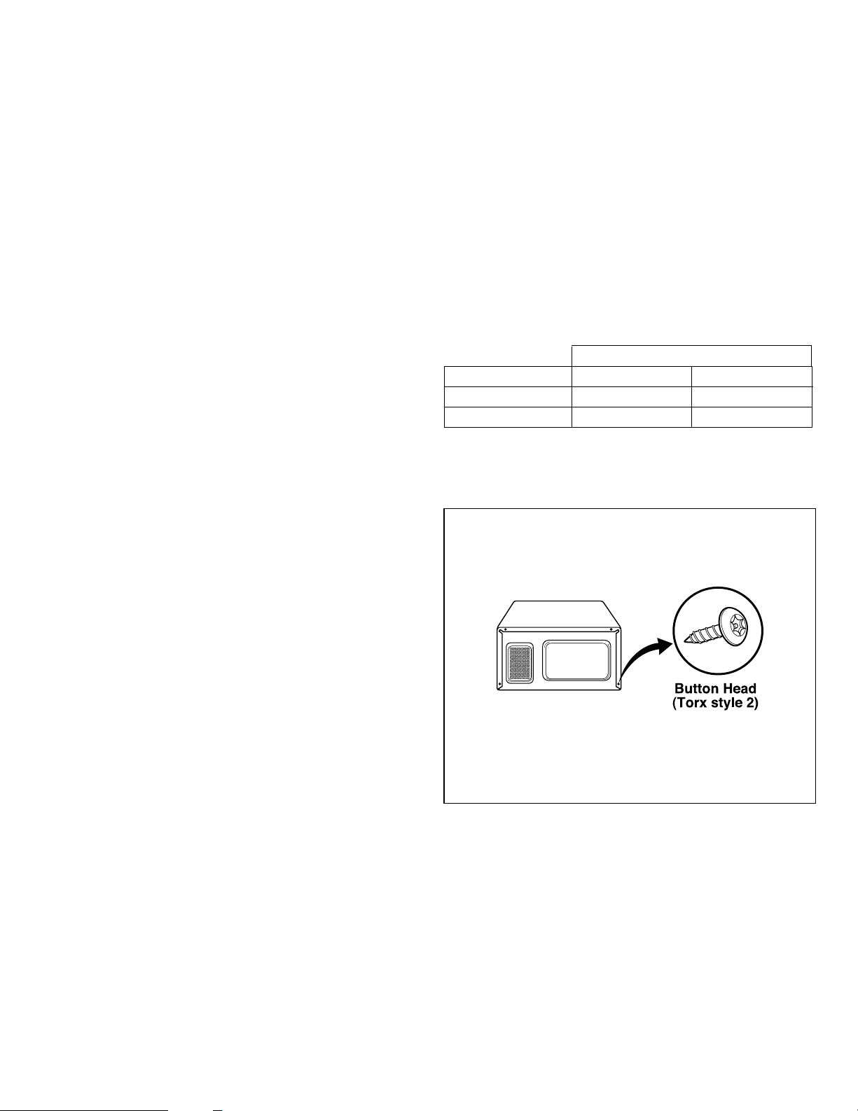
SPECIAL TIP
• This oven used the button head screws.
• When you remove the screws, using the
tamper-resistant Torx driver have a
pin-in-head.
-11-
Line Voltage Degrees °F Degrees °C
120 V 17.1 ~ 22.5 9.5 ~ 12.5
108 V Min. 12.6 Min. 7.0
Temperature Rise
Page 13

securing
screw
9. DISASSEMBLY INSTRUCTIONS
IMPORTANT NOTES:
UNIT MUST BE DISCONNECTED FROM ELECTRICAL
OUTLET WHEN MAKING REPAIRS, RE-PLACEMENTS,
ADJUSTMENTS AND CONTINUITY CHECKS. WAIT AT
LEAST ONE MINUTE, UNTIL THE HIGH VOLTAGE
CAPACITOR IN THE HIGH VOLTAGE POWER
SUPPLY HAS FULLY DISCHARGED. THE CAPACITOR
SHOULD BE DISCHARGED BY USING INSULATED
WIRE - I.E. TEST PROBE CONNECTED TO 10KOHM
RESISTOR IN SERIES TO GROUND. WHEN
RECONNECTING THE WIRE LEADS TO ANY PART,
MAKE SURE THE WIRING CONNECTIONS AND LEAD
COLORS ARE CORRECTLY MATCHED ACCORDING
TO THE OVERALL CIRCUIT DIAGRAM. (ESPECIALLY
SWITCHES ANDHIGH VOLTAGE CIRCUIT.)
A. REMOVING OUT CASE (Figures 7)
(1) Remove four screws from the rear section.
(2) Remove one screw from the side section.
(3) Push the outer case back about 1 inch (3cm).
(4) Lift the case from the set.
B. REMOVING COFFEE MAKER ASSEMBLY(Figure 8)
CAUTION: BE CAREFUL HOT SURFACE!
AFTER TOASTING, ENTIRE TOASTER’S
SURFACES ARE VERY HOT. BEFORE
SERVICING, COOL DOWN THE TOASTER
PARTS ENOUGH NOT TO GET BURNT.
(1) Open the door.
(2) Remove 2 screws, holding the toaster.
(3) Disconnect the 2 lead wires from connectors(CN2,CN3).
(4) Disconnect the wires at the secondary interlock switch
and wires at the toaster door switch.
(5) Disconnect the wires from the toaster thermostat and
wires at the Toaster Assembly.
(6) Lift up and pull out Toaster Assembly carefully from the
cavity.
Remove screw
Lift up and pull out toaster assembly
-12-
Page 14

-13-
C. DOOR GROSS ASSEMBLY REMOVAL
(1) Open the door.
(2) Remove the choke cover cap very carefully with a flat-blade
screwdriver.
CAUTION : Be careful not to damage door seal plate by
screwdriver.
(3) Lift up and push the door.
NOTE:
1. After replacing the door, be sure to check that the primary
switch, monitor switch, and secondary switch operate
normally.
2. After replacing the door, check for microwave energy leakage
with a survey meter. Microwave energy must be below the
limit of 5 mW/cm.sq. (with a 275 ml water load)
3. When mounting the door assembly to the oven assembly, be
sure to adjust the door assembly parallel to the chassis. Also
adjust so the door has no play between the inner door surface
and oven frame assembly. If the door assembly is not
mounted properly, microwaves may leak from the clearance
between the door and the oven.
Page 15

D. MAGNETRON REMOVAL (Figure 10)
1) Disconnect the wire lead from the magnetron.
2) Carefully remove the mounting screws holding the
magnetron and the waveguide.
3) Remove the magnetron assembly until the tube is clear
from the waveguide.
NOTE:
1. When removing the magnetron, make sure its dome
does not hit any adjacent parts, or it may be damaged.
2. When replacing the magnetron, be sure to install the
magnetron gasket in the correct position and be sure
that the gasket is in good condition.
3. After replacing the magnetron, check for microwave
leakage with a survey meter around the magnetron.
Microwave energy must be below the limit of 5 mW/cm2.
(With a 275 ml. water load).
Make sure that gasket is rigidly attached to the
magnetron. To prevent microwave leakage, tighten the
mounting screws properly, making sure there is no gap
between the waveguide and the magnetron.
E. REMOVING THE TURNTABLE MOTOR (Figure 11)
1) Remove the turntable and rotating ring.
2) Lay the unit down on its back.
3) Remove the turntable motor cover.
The turntable base cover is easily removed by pinching
the eight parts with a wire cutting.
4) Disconnect the leadwire from the turntable motor
terminals.
5) Remove the screw securing the turntable motor to the
oven cavity ASSEMBLY.
6) After repairing the motor, rotate the removed turntable
motor cover.
7) Fit the turntable motor cover’s projecting part to the base
plate slit.
NOTE:
1. Remove the wire lead from the turntable motor VERY
CAREFULLY.
2. Be sure to grasp the connector, not the wires, when
removing.
-14-
Magnetron
Waveguide
Magnetron
Gasket
Magnetron
Dome
Waveguide
Bracket
Turntable
Motor
Wire Leads
Page 16

F. HIGH VOLTAGE TRANSFORMER REMOVAL
1) Discharge the high voltage capacitor.
2) Disconnect the leadwire from magnetron, high voltage
transformer, and capacitor.
3) Remove the screw holding the high voltage transformer to
the baseplate.
G. FAN MOTOR ASSEMBLY REMOVAL
1) Discharge the high voltage capacitor.
2) Disconnect the leadwire from fan motor and high voltage
capacitor.
3) Remove the two screws holding the the suction guide
ASSEMBLY to the oven cavity.
4) Remove the two screws holding the fan motor ASSEMBLY
to the suction guide ASSEMBLY.
H. HIGH VOLTAGE CAPACITOR AND DIODE REMOVAL
1) Discharge the high voltage capacitor.
2) Disconnect the leadwire from fan motor and high voltage
capacitor.
3) Remove the screw holding the suction guide ASSEMBLY to
the oven cavity.
4) Remove the screw holding the high voltage capacitor
bracket and remove the high voltage diode earth screw.
I. INTERLOCK SYSTEM
1) INTERLOCK MECHANISM
The door lock mechanism is a device which has been
specially designed to eliminate completely microwave
activity when the door is opened during cooking and thus
to prevent the danger resulting from the microwave
leakage.
2) MOUNTING OF THE PRIMARY/MONITOR/
SECONDARY SWITCHES TO THE LATCH BOARD
3) INSTALLATION AND ADJUSTMENT OF THE LATCH
BOARD TO THE OVEN ASSEMBLY
• Mount the latch board to the oven assembly.
• Adjust the latch board in the arrow direction so that oven
door will not have any play in it when the door is closed.
• Tighten the mounting screw.
• Check for play in the door by pushing the door
release button. Door movement should be less than
0.5 mm. (1/64 inch)
Don't push the door release button while making this
adjustment. Make sure that the latch moves smoothly after
adjustment is completed and that the screws are tight.
Make sure the primary, monitor, and secondary switches
operate properly by following the continuity test
procedure.
-15-
Page 17

-16-
A. PRIMARY INTERLOCK SWITCH TEST
When the door release button is depressed slowly with
the door closed, an audible click should be heard at
the same time or successively at intervals. When the
button is released slowly, the latches should activate
the switches with an audible click.
If the latches do not activate the switches when the
door is closed, the switches should be a adjusted in
accordance with the adjustment procedure. Disconnect
the wire lead from the primary switch. Connect the
ohmmeter leads to the common (COM) and normally
open (NO) terminal of the switch. The meter should
indicate an open circuit in the door open condition.
When the door is closed, the meter should indicate a
closed circuit.
When the primary switch operation is abnormal, make
the necessary adjustment or replace the switch only
with the same type of switch.
B. SECONDARY INTERLOCK SWITCH TEST
Disconnect the wire lead from the secondary switch.
Connect the ohmmeter leads to the common (COM)
and normally open (NO) terminals of the switch. The
meter should indicate a open circuit in the door open
condition. When the door is closed, meter should
indicate an closed circuit. When the secondary switch
operation is abnormal, make the necessary adjustment
or replace the switch only with the same type of switch.
C. MONITOR SWITCH TEST
Disconnect the wire lead from the monitor switch.
Connect the ohmmeter leads to the common (COM)
and normally closed (NC) terminals of the switch. The
meter should indicate closed circuit in the door open
condition. When the door is closed, meter should
indicate an open circuit. When the monitor switch
operation is abnormal, replace with the same type of
switch.
NOTE: After repairing the door or the interlock system,
it is necessary to do this continuity test before
operating the oven.
10. INTERLOCK CONTINUITY TEST
WARNING : FOR CONTINUED PROTECTION AGAINST EXCESSIVE RADIATION
EMISSION, REPLACE ONLY WITH IDENTICAL REPLACEMENT PARTS.
TYPE NO. SZM-V 16-FA-63 OR VP-533A-OF FOR PRIMARY SWITCH
TYPE NO. SZM-V 16-FA-62 OR VP-532A-OF FOR MONITOR SWITCH
TYPE NO. SZM-V 16-FA-63 OR VP-533A-OF FOR SECONDARY SWITCH
COMPONENTS TEST PROCEDURE RESULTS
SWITCHES Check for continuity of the Door Door
(Wire leads removed) switch with an Ohm-meter open closed
Primary
Switch
Monitor
Switch
Secondary
Switch
NOTE : After checking for the continuity of switches, make sure that they are
connected correctly.
COM
COM
NO
NC
NO
COM
Page 18

-17-
11. TEST AND CHECKOUT PROCEDURES, AND TROUBLESHOOTING
A. TEST PROCEDURES
CAUTIONS
1. DISCONNECT THE POWER SUPPLY CORD FROM THE OUTLET WHENEVER REMOVING THE OUTER CASE
FROM THE UNIT. PROCEED WITH THE TEST ONLY AFTER DISCHARGING THE HIGH VOLTAGE CAPACITOR
AND REMOVING THE WIRE LEADS FROM THE PRIMARY WINDING OF THE HIGH VOLTAGE
TRANSFORMER.
2. ALL OPERATIONAL CHECKS WITH MICROWAVE ENERGY MUST BE DONE WITH A LOAD (1 LITER OF
WATER IN CONTAINER) IN THE OVEN.
HIGH VOLTAGE
TRANSFORMER
(Wire leads removed)
MAGNETRON
(Wire leads removed)
Approx.: 0.7 ~ 0.9 ohm
Approx.: 90 ~ 120 ohm
Less than: 1 ohm
Normal: Infinite
Normal: Infinite
Normal: Less than 1 ohm
Normal: Infinite
FILAMENT
WINDING
PRIMARY
TERMINAL
SECONDARY
WINDING
COMPONENTS TEST PROCEDURE RESULTS
1. Measure the resistance.
(Select the ohm scale on the meter)
• Primary winding
• Secondary winding
• Filament winding
2. Measure the resistance.
(Select the ohm scale on the meter)
• Primary winding to ground
• Filament winding to ground
1. Measure the resistance.
(Select the ohm scale on the meter)
• Filament terminal
2. Measure the resistance.
(Select the ohm scale on the meter)
• Filament to chassis
Page 19

-18-
NOTE: When testing the magnetron, be sure to install the magnetron gasket in the
correct position and be sure that the gasket is in good condition.
Antenna
Gasket
Chassis
Filament
HIGH VOLTAGE
CAPACITOR
1. Check DC 9V battery before performing
tests.
2. Select the DCV scale on the meter.
3. Using the meter, battery, and jump wire,
connect the items as illustrated in figures.
• Terminal to terminal.
Normal: Approximately 9V
Normal: Approximately 0V or a
value displayed in mV
Will be seen.
1. Check DC 9V battery before performing
tests.
2. Select the DCV scale on the meter.
3. Using the meter, battery, and jump wire,
connect the items as illustrated in figures.
• Terminal to case.
COMPONENTS TEST PROCEDURE RESULTS
Page 20

-19-
H.V.Diode (rectifer) STEP 1. Test the diode to see if it is shorted.
Procedure:
1. Select the Ω scale on the meter.
2. Place the meter leads across the diode as
pictured in Figure 14-a. The reading should be
“40MΩ,” “OL,” or a reading of infinity.
3. Reverse the meter leads. The reading should
again indicate a reading of infinity. If the diode
shows “infinity” in BOTH directions, it is NOT
shorted.
4. If the diode is not shorted, proceed to step 2.
STEP 2. Test the diode for forward biasing.
Procedure:
1. Select the DCV scale on the meter.
2. Using the meter, battery, and jumper wire,
connect the items as illustrated in Figure 14-b.
This has the positive side of the battery
connected to the cathode of the diode.
3. The diode should be forward biased therefore
a voltage reading of approximately 4.7 VDC to
6.4 VDC will be read depending on meter, battery
strength, etc. (Note: If the meter leads were
reversed, a negative voltage of the same amount
would be seen.)
STEP 3. Test the diode for reverse biasing.
Procedure:
1. Using the same scale on the meter, connect
the positive side of the battery to the anode of the
diode as illustrated in Figure 14-c.
2. The diode should be reverse biased therefore
a reading of 0 volt or a value displayed in mV will
be seen. (The display will be erratic changing
values rapidly in the mV scale.)
Normal:
Approximately
4 .7-6.4V
Normal:
Approximately 0V
COMPONENTS TEST PROCEDURE RESULTS
Figures 14-a Figures 14-b Figures 14-c
Page 21

-20-
COMPONENTS TEST PROCEDURE RESULTS
RELAY 2
(Power Relay)
FAN MOTOR
TURNTABLE
MOTOR
1. Measure continuity.
2. Remove the lead wires and operate oven
at power level 1 through power level 10.
NOTE : • A MICROWAVE LEAKAGE TEST MUST ALWAYS BE PERFORMED WHEN THE UNIT IS SERVICED FOR ANY
REASON.
• MAKE SURE THE WIRE LEADS ARE IN THE CORRECT POSITION.
• WHEN REMOVING THE WIRE LEADS FROM THE PARTS, BE SURE TO GRASP THE CONNECTOR, NOT THE
WIRES.
1. Remove wire leads.
2. Measure resistance.
Normal:
A: Approximately
95~120 ohms.
B: Approximately
10~25 ohms.
Abnormal:
Infinite
Normal: Approx.2.5~3.5 Kohms
Abnormal: Infinite or several
ohm.
POWER
LEVEL
1
2
3
4
5
6
7
8
9
10
4 sec
6 sec
8 sec
10 sec
12 sec
14 sec
16 sec
18 sec
20 sec
22 sec
18 sec
16 sec
14 sec
12 sec
10 sec
8 sec
6 sec
4 sec
2 sec
0 sec
1. Remove wire leads.
2. Measure resistance.
Page 22

B. CHECKOUT PROCEDURES
(1) CHECKOUT PROCEDURES FOR FUSE BLOWING
CAUTION: REPLACE BLOWN FUSE WITH 15 AMPERE FUSE.
NOTES:
- If the fuse is blown by an improper switch operation, replace the defective switches and the fuse at the same time.
After replacing the defective switches with new ones, make sure that they are correctly connected.
- Check for microwave energy leakage according to “1. ADJUSTMENT PROCEDURES” on page 3, when the
primary interlock, secondary interlock switches and/or the interlock monitor switches are adjusted or replaced.
-21-
PROBLEMS CAUSES
Fuse blows immediately after
the door is closed.
Improper operation of the primary interlock,
secondary interlock switches and/or the interlock
monitor switch.
Malfunction of the high voltage transformer; the high
voltage capacitor including the diode, the magnetron,
the blower motor or the circuit board.
Fuse blows immediately after
the door is opened.
Fuse blows when the door is closed and START key
is touched.
Page 23

-22-
(2) CHECKOUT PROCEDURES FOR RELAY.
Microwave Oven
Toaster
- PROBLEM (A) FAN motor and oven lamp turn on without touching
START key when the door is closed.
Remove the mate connector of I/O
CON from the circuit board does
the unit still operate?
Replace the
circuit board
NO
NO
YES
GOOD
- PROBLEM (B) -
FAN motor and oven lamp turn on When the door is
closed and START key is touched.
Check the interlock switches
Replace the
micro switches.
Defective
RELAY or poor
connection of
relay
Replace
RELAY or correct
the connection.
YES
NO
NO
YES
GOOD
- PROBLEM (A) FAN motor and indicator light turn on without touching
START key when the door is closed.
Remove the mate connector of I/O
CON from the circuit board does
the unit still operate?
Replace the
circuit board
NO
NO
YES
GOOD
- PROBLEM (B) -
FAN motor and indicator light turn on When the door
is closed and START key is touched.
Check the interlock switches
Replace the
micro switches.
Defective
RELAY or poor
connection of
relay
Replace
RELAY or correct
the connection.
YES
NO
NO
YES
GOOD
Page 24

(3) CHECKOUT PROCEDURES FOR CIRCUIT BOARD
The following symptoms indicate a defective circuit
board.
(1) The start function fails to operate but the high
voltage Systems, the interlock switches, the door
sensing and the relay check good.
(2) The unit with a normal relay continuously operates.
(3) The buzzer does not sound or continues to sound.
(4) Some segments of one or more digits do not light up, or
they continue to light up, or segments light when they
should not.
(6) Wrong figures appear.
(7) The figures of all digits flicker.
(8) Some of the indicators do no light up.
(9) The clock does not keep time properly.
-23-
NOTE: A MICROWAVE ENERGY LEAKAGE TEST MUST ALWAYS BE PERFORMED WHEN THE UNIT IS
SERVICED FOR ANY REASON.
Page 25

-24-
CONDITION
Toaster and Microwave oven
does not work.
Inserting many plugs into one
outlet and using them at the
same time
(blown fuse or breaker)
Plug is not inserted tightly.
Output power is too low. Low AC input voltage.
Food temperature is too low.
Using metallic ware and
allowing it to touch the oven
wall.
Sparks occur in oven.
Inconsistent intensity of
microwave by their
characteristics.
1. Use plastic wrap or lid.
2. Stir once or twice while
cooking soup, cocoa or
milk, etc.
Uneven microwave cooking.
Ceramic ware trimmed in
gold or silver powder is used.
Avoid using other electrical
appliances when you use this
unit.
Insert plug securely.
Use the this machine at
adequate line voltage.
This may not be a defect.
It is possible that the food
should be cooked for a
longer time period.
Do not use metallic ware for
cooking except where noted
in the cooking guide.
Do not use any type of
cookware with metallic
trimming.
CAUSE REMEDY
C. TROUBLE SHOOTING
CAUTIONS
1. Check grounding and cool this unit before checking for trouble.
2. Be careful of the high voltage circuit.
3. Discharge the high voltage capacitor.
4. When checking the continuity of the switches or of the high voltage transformer, disconnect one lead wire from these
parts and then check continuity with the AC plug removed. To do otherwise may result in a false reading or damage
to your meter.
5. Do not touch any part of the circuit on the PCB since static electric discharge may damage this control panel.
Always touch yourself to ground while working on this panel to discharge any static charge built up in your body.
(Micom model only)
WHEN YOU GET A COMPLAINT FROM YOUR CUSTOMER, EVALUATE THE COMPLAINT CAREFULLY. IF THE
FOLLOWING SYMPTOMS APPLY, PLEASE INSTRUCT THE CUSTOMER IN THE PROPER USE OF THE TOASTER AND
MICROWAVE OVEN. THIS CAN ELIMINATE AN UNNECESSARY SERVICE CALL.
Page 26

-25-
CONDITION CHECK RESULT CAUSE REMEDY
1. No input can be
programmed.
Continuity.
No continuity.
Defective PCB
assembly.
Replace PCB
assembly.
Check the connection between
membrane key
assembly and
PCB assembly.
Replace key
membrane
assembly and
check operation.
2. Some inputs
cannot be
programmed.
4. Random
programming
when touching
other pads.
5. Display is fixed
at some figure
and can not
accept any
input.
3. Display shows a
number or figure
different from one
touched.
Everything works
as specified.
Still have trouble.
Loose
connection.
Connect them
tightly.
Defective key
membrane
assembly.
Replace key
membrane
assembly.
Defective PCB
assembly.
Replace PCB
assembly.
(TROUBLE 1) The following visual conditions indicate a probable defective control circuit.
1. Incomplete segments.
• Segment missing.
• Partial segment missing.
• Digit flickering (NOTE: Slight flickering is normal.)
2. Colon does not turn on or blink.
3. A distinct change in the brightness of one or more numbers in display.
4. One or more digits in the display are not lighting.
5. Display indicates a number different from one touched, for example, key in 5 and 3 appears in the display.
6. Specific numbers (for example 7 or 9) will not display when key pad is touched.
7. Display does not count down with time blinking or up with clock operation.
8. Display obviously jumps in time while counting down.
9. Display counts down too fast while cooking.
10. Each indicator light does not turn on after setting cooking cycle.
11. Display time of day does not reappear when cooking is finished.
Page 27

-26-
2. Fuse does not
blow.
No continuity.
Continuity.
No continuity.
Defective power
supply cord.
Replace power
supply cord.
Defective
thermostat.
Replace
thermostat.
Check continuity
of thermostat.
Check continuity
of power supply
cord.
CONDITION CHECK RESULT CAUSE REMEDY
(TROUBLE 2) Microwave oven does not operate at all, Display window does not display any figures,
and no input is accepted.
1. Fuse blows.
Continuity.
No continuity.
Malfunction of the
monitor switch.
Replace fuse,
primary, monitor,
switches, and
RELAY(RY2) of
P.C.B Assembly.
Check continuity
of monitor
switch (with
door closed).
Continuity.
No continuity.
Shorted contact at
the primary switch.
Replace fuse,
primary, monitor,
switches, and
RELAY(RY2) of
P.C.B Assembly.
Check continuity
of primary
switch (with
door opened)
Normal.
Replace fuse
Fuse blows again
Defective high
voltage capacitor.
Replace high
voltage capacitor.
Disconnect one
side of the wire
lead connected
from transformer
to the high
voltage
capacitor and
operate the unit.
Defective high voltage transformer.
Replace high voltage transformer.
Page 28

-27-
(TROUBLE 3) Display shows all figures set, but microwave oven does not start cooking while desired
program times are set and START pad is touched.
(TROUBLE 4) Microwave oven seems to be operating but little heat is produced in oven load.
1.Setting time
does not count
down when
touching START
pad.
2. Fan motor or
oven lamp do
not turn on.
No continuity.
Continuity.
Defective
secondary switch.
Replace
secondary switch.
Check continuity
of secondary
switch (with
door closed).
Check the connection between
CN1 connector
and PCB
assembly.
Continuity
No continuity
Abnormal
Abnormal
Normal
Defective fan motor.
Defective oven lamp.
Defective PCB
assembly.
Loose connection.
Output is low.
Lower than 90% of
rating voltage.
Normal.
Decrease in power
source voltage
with load.
Suggest customer
contact local
electric power
utility co. or
qualified
electrician.
Check the
power source
voltage.
Disconnect the
wire leads from
relay 2 and
check on and off
time with
multitester.
Measure the
output power.
Abnormal.
Abnormal.
Normal.
Defective PCB
assembly.
Defective
magnetron.
Replace PCB
assembly.
Replace
magnetron.
Replace PCB
assembly.
Connect them
tightly.
Replace fan motor.
Replace
oven lamp.
Check fan motor.
Check oven lamp.
CONDITION CHECK RESULT CAUSE REMEDY
CONDITION CHECK RESULT CAUSE REMEDY
NOTE: Simple test of power output-conducted by heating one liter water for one min. if available.
Minimum 8.5oC temperature rise is normal condition.
Page 29

-28-
CONDITION CHECK RESULT CAUSE REMEDY
(TROUBLE 5) No microwave oscillation even though oven lamp and fan motor run.
(Display operates properly)
No microwave
oscillation.
No continuity.
Continuity.
Disconnect the
wire leads from
relay 2 and
check continuity
of relay 2.
(Operate the unit)
Defective PCB
assembly
Defective high
voltage
transformer.
Replace PCB
assembly
Output is full power
when you set lower
power level.
Abnormal.
Disconnect the
wire leads from
relay 2 and check
continuity relay 2.
(Operate the unit)
Defective PCB
assembly
Replace PCB
assembly
Replace high
voltage
transformer.
Defective high
voltage capacitor.
Replace high
voltage capacitor.
Abnormal
Normal
Check high voltage transformer
Abnormal
Normal
Check high voltage capacitor.
Defective high
voltage diode.
Replace high
voltage diode.
Abnormal
Normal
Check high voltage diode.
Defective
magnetron.
Replace
magnetron.
Abnormal
Check
magnetron.
NOTE: • Make sure the wire leads correct position.
• When Removing the wire leads from the parts, be sure to grasp the connector, not the wires.
• When removing the magnetron, be sure to install the magnetron gasket in the correct position
and in good condition.
Page 30

-29-
(TROUBLE 6) When toaster operates, strange code can be seen on the display and stop with beep sound.
1. “F-1” code.
No continuity.
Continuity.
Defective
thermistor
Replace thermistor
Check continuity
of thermistor.
Check the
continuity of
heater.
Check the
connection
between CN3
connector and
PCB assembly.
Continuity.
No continuity.
Continuity.
No continuity.
Defective heater
Defective PCB
assembly.
2. “F-2” code.
Attached
Seperated
2 wire leads are
shorted contact
Internal
temperature is
over 220 deg c
Apart 2 wire leads
as far as possible.
Check the CN3
connector
whether 2 wire
leads are
attached.
3. “HOT” code.
Allow the toaster to
cool down.
(Automatically fan
will blow for
3 minutes to cool
this unit)
Defective PCB
assembly.
Replace PCB
assembly.
Replace toaster
Assembly.
Replace PCB
Assembly.
Loose connection
Connect them
tightly.
CONDITION CHECK RESULT CAUSE REMEDY
Page 31

-30-
EXPLODED VIEW
INTRODUCTION
Page 32

-31-
DOOR PARTS
14890A
13213A
13536A
13552A
15006A
13581A
14026A
14970A
WTP004
268712
13720D
13650A
13551A
For model
LTRM1240ST
23506A
For model
LTRM1240SB
LTRM1240SW
WTT028
Page 33

-32-
OVEN CAVITY PARTS
33112U
WTT010
WTT020
33390G
35889A
WTP013
36549S
33052A
WSZ185
LTRM1240SB
LTRM1240ST
For model
For model
LTRM1240SW
Page 34

-33-
LATCH BOARD PARTS
WSZ085
56912B
55262A
466003
466001
466001
43500A
44510A
Page 35

-34-
OVEN INTERIOR PARTS
568771
56930V
WTT028
56324A
WSZ002
WTT028
56851D
WSZ002
54810C
50CZZH
WSZ002
55900A
54974S
56549F
568772
WTT037
WSZ002
56411A
WTT024
34930W
35012A
55006F
50FZZA
WSZ
002
268711
Page 36

-35-
BASE PLATE PARTS
63302A
WTT021
65006A
647781
WTT028
WTT021
WSZ002
56170D
63303A
Page 37

-36-
SENSOR PARTS
WTP004
56501A
WTT021
54974T
Page 38

-37-
COFFEE MAKER PARTS
75993M
73550L
768711
74970A
73650A
73551B
73720D
73213A
73552A
73572A
73740A
73551C
73551A
766001
74510L
76322A
76930V
For LTRM1240ST
For LTRM1240ST
Page 39

 Loading...