

LG LTNE1860HL INSTALLATION INSTRUCTIONS
ENGLISH ITALIANO ESPAÑOL FRANÇAIS DEUTSCH
CEILING CASSETTE TYPE AIR CONDITIONERS
INSTALLATION INSTRUCTIONS
• Please read this instruction sheet completely before installing the product.
• When the power cord is damaged, replacement work should be performed by authorized personnel
only.
• Installation work should be performed in accordance with national wiring standards by authorized
personnel only.
P/No.: 3828A20055P
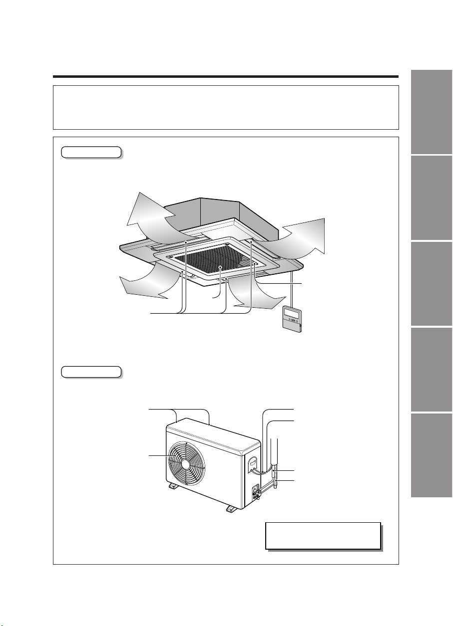
Outdoor Unit
Indoor Unit
Cooling & Heating Model has
included Drain Elbow
Anti-bacteria filter
Air
Intake
Air Outlet
Air Intake
(side, rear)
Connecting Wire
Drain Hose
Power Wire
Connection Tube
Air Outlet
Vents

2
1.The following should be always observed for safety
...............................
3
2.Installation of Indoor, Outdoor Unit
............................................................
4
3. Test running
..............................................................................................
15
4. Auxiliary operation
...................................................................................
17
OUT-LINE OF INSTALLATION
Installation Parts
Required Tools
Installation Works
•
Connecting cable
• Pipes: Gas side
Liquid side
• Hanging Bolt
(W 3/8 or M10 length
650mm)
• Insulated drain hose
• Additional Drain hose
(Inner Dia.............32mm)
•
Level
•
Screw driver
•
Electric drill
•
Hole core drill (ø70mm)
• Flaring Tools set
• Torque Wrenches
• Hexagonal Wrench
(4mm, 5mm)
• Gas-leak detector
•
Owner’s Manual
•
Thermometer
1) Selection of the best location......................4
2) Ceiling opening dimensions and hanging
bolt location(unit: mm).................................5
3) The Indoor Unit Installation.........................6
4) Remote Controller Installation ....................6
5) Wiring Connection.......................................8
ELECTRICAL WIRING................................9
CONNECTING THE CABLE TO OUTDOOR UNIT
......9
6) Connecting Pipes to the Indoor Unit.........10
PIPING CONNECTION.............................11
7) Installation of Decorative Panel.................12
8) Indoor Unit Drain Piping............................13
HEAT INSULATION...................................14
FORM THE PIPINGS................................14
1) PRECAUTIONS IN TEST RUN .................15
CHECK THE FOLLOWING ITEMS WHEN
INSTALLATION IS COMPLETE................15
2) Connection of power supply......................16
3) Evaluation of the performance..................16
1) Two thermistor system ..............................17
2) Ajusting to the height of ceiling.................18
3) Group control (optional wiring)..................19
4) Central control (optional)...........................20
1. The following should be always observed for safety
3
ENGLISH
• Please report to or take consent by the supply authority before connecting to the system.
• Be sure to read "THE FOLLOWING SHOULD BE ALWAYS OBSERVED FOR SAFETY" before
installing the air conditioner.
• Be sure to observe the cautions specified here as they include important items related to safety.
• The indications and meanings are as follows.
• After reading this manual, be sure to keep it together with the instruction manual in a handy place .
Could lead to death, serious injury, etc.
Do not install it yourself (customer).
Perform the installation securely referring to the
installation manual.
Install the unit securely in a place which can bear the
weight of the unit.
Perform electrical work according to the installation
manual and be sure to use an exclusive circuit.
Attach the electrical part cover to the indoor unit and
the service panel to the outdoor unit securely.
Be sure to use the part provided or specified parts for
the installation work.
Check that the refrigerant gas do not leak after
installation is completed.
Perform the drainage/piping w ork securely
according to the installation manual.
Use the specified wires to connect the indoor and the
outdoor units securely and attach the wires firmly to
the terminal board connecting sections so the stress
of the wires is not applied to the sections.
• Incomplete installation could cause injury due to fire, electric shock,
the unit falling or a leakage of water. Consult the dealer from whom
you purchased the unit or special installer.
• Incomplete installation could cause a personal injury due to
fire, electric shock, the unit falling or a leakage of water.
• When installed in an insufficient strong place, the unit could fall
causing injured.
• Incomplete connecting and fixing could cause fire.
• If the capacity of the power circuit is insufficient or there is
incomplete electrical work, it could result in a fire or an electric
shock.
• The use of defective par ts could cause an injury or leakage of
water due to a fire, electric shock, the unit f alling, etc.
• If there is a defect in the drainage/piping work, water
could drop from the unit and household goods could be
wet and damaged.
Do not install the unit in a place where an
inflammable gas leaks.
• If gas leaks and accumulates in the area surrounding the unit, it
could cause an explosion.
• If the electrical part cover if the indoor unit and/or the service
panel if the outdoor unit are not attached securely, it could result
in a fire or electric shock due to dust, water , etc.
Could lead to serious injury in particular environments when operated incorrectly.
WARNING
WARNING
CAUTION
CAUTION
Perform gr ounding
• Do not connect the ground wire to a gas pipe, water pipe arrester or
telephone ground wire. Defective grounding could cause an electric
shock.
4
1. Selection of the best location
1) Indoor unit
• There should not be any heat source or
steam near the unit.
• There should not be any obstacles to
prevent the air circulation.
• A place where air circulation in the room will
be good.
• A place where drainage can be easily
obtained.
• A place where noise prevention is taken into
consideration.
• Do not install the unit near the door way.
• Ensure the spaces indicated by arrows from
the wall, ceiling, or other obstacles.
• The indoor unit must keep the maintenance
space.
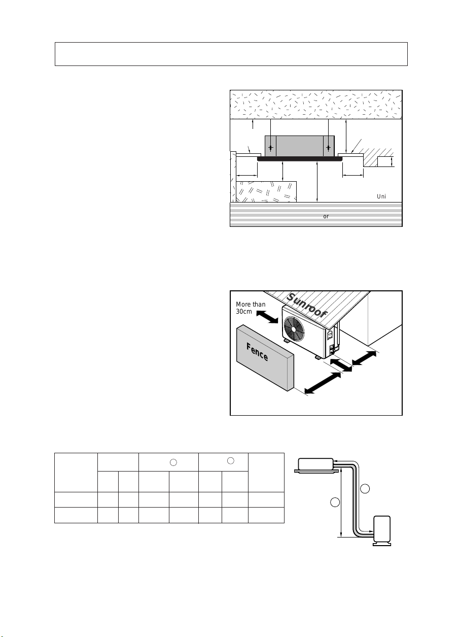
2) Outdoor unit
• If an awning is built over the unit to prevent
direct sunlight or rain exposure, be careful
that heat radiation from the condenser is not
restricted.
• There should not be any animals or plants
which could be affected by hot air
discharged.
• Ensure the spaces indicated by arrows from
the wall, ceiling, fence or other obstacles.
Unit:cm
Ceiling
Ceiling Board
Ceiling Board
30 or more
Above 250
330 or less
100
or more
50 or
more
50 or
more
30 or less
Floor
Indoor unit
Outdoor unit
B
A
2. Installation of Indoor, Outdoor Unit
CAP A CITY
18K Btu/h
5/8" 1/4"7.5 50
24
K Btu/h
5/8" 1/4"7.5 50
GAS LIQUID
5 30 25
5 30 30
Elevation B (m)
Length A (m)
* Additional
refrigerant
(g/m)
Pipe Size
Rated Rated
Max. Max.
• Rated performance for refrigerant line length of: 7.5m
• If 18K Model is installed at a distance of 15m, 187.5g of refrigerant
should be added ..................................................................(15-7.5)x25g
3) Piping length and the elevation
More than
30cm
Fence or
obstacles
Sunroof
More thanMore than
More than
30cm30cm
30cm
More than 50cm
More than 70cm
ENGLISH
5
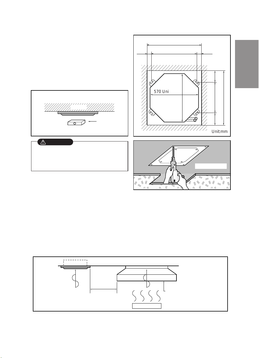
• The dimensions of the paper model for installing
are the same as those of the ceiling opening
dimensions.
•
Select and mark the position for fixing bolts and piping hole.
•
Decide the position for fixing bolts slightly tilted to the drain
direction after considering the direction of drain hose
.
• Drill the hole for anchor bolt on the wall.
,,,
Unit:mm
570 Unit size
570 Unit size
450 (Hanging bolt)
7575
600 (Ceiling opening)
600 (Ceiling opening)
521(Hanging bolt)
39.5
39.5
Ceiling board
Level gauge
Ceiling
Use the ventilation fan
for smoke-collecting
hood with sufficient
capacity.
Cooking table
Air conditioner
Take enough
distance
• This air-conditioner uses a drain pump.
• Horizontly install the unit using a level gauge.
• During the installation, care should be taken not to
damage electric wires.
2. Ceiling opening dimensions and hanging bolt location
NOTE:
• Thoroughly study the following installation locations:
1. In such places as restaurants and kitchens, considerable amount of oil steam and flour adhere to the
turbo fan, the fin of the heat exchanger and the drain pump, resulting in heat exchange reduction,
spraying, dispersing of water drops, drain pump malfunction, etc.
In these cases, take the following actions:
• Make sure that the ventilation fan for smoke-collecting hood on a cooking table has sufficient
capacity so that it draws oily steam which should not flow into the suction of the air conditioner.
• Make enough distance from a cooking room to install the air conditioner in such a place where it may
not suck in oily steam.
2. Avoid installing air conditioner in such circumstances where cutting oil mist or iron powder is in
suspension in factories, etc.
3. Avoid places where inflammable gas is generated, flows in, is stored or vented.
4. Avoid places where sulfurous acid gas or corrosive gas is generated.
5. Avoid places near high frequency generators.
CAUTION
6
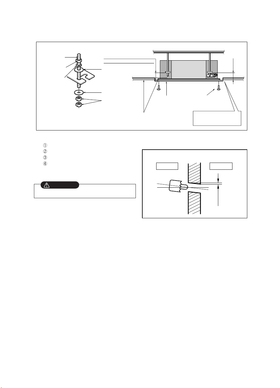
3. The Indoor Unit Installation
• The following parts is option.
Hanging Bolt - W 3/8 or M10
Nut - W 3/8 or M10
Spring Washer - M10
Plate Washer - M10
• Drill the piping hole on the wall slightly tilted to the
outdoor side using a Ø 70 hole-core drill.
Wall
5~7mm
Indoor Outdoor
Set screw of
paper model (4 pieces)
Paper model
for installation
Ceiling board
150mm
Adjust the same height
Ceiling board
Ceiling
Flat washer for M10
(accessory)
Keep the length of the bolt
from the bracket to 40mm
Open the ceiling board
along the outer edge of the
paper model
Flat washer for M10
(accessory)
Hanging bolt
(W3/8 or M10)
Nut
(W3/8 or M10)
Nut
(W3/8 or M10)
Spring washer
(M10)
Air Conditioner body
• Tighten the nut and bolt to prevent unit falling.
4. Remote Controller Installation
• Although the room temperature sensor is in the indoor unit, the remote controller should be installed in
such places away from direct sunlight and high humidity.
Installation of the remote controller
• Select places that are not splashed with water.
• Select control position after receiving customer approval.
• The room temperature sensor is built in the indoor unit.
• This remote controller equipped with liquid crystal display. If this position is higher or lower, display is difficult to
see.(The standard height is 1.2 ~ 1.5m high)
Routing of the remote controller cord
• Keep the remote controller cord away from the refrigerant piping and the drain piping.
• To protect the remote controller cord from electrical noise, place the cord at least 5cm away from other power
cables (audio equipment, television set, etc.)
• If the remote controller cord is secured to the wall, provide a trap at the top of the cord to prevent water droplets
from running.
CAUTION
 Loading...