

LG LT303N-B Owner’s Manual

Dome Camera
Owner’s Manual
MODEL: LT303
Before installing and using the camera, please read this owner's
manual carefully and retain for future reference.
LT303N-B.CSAUBLI_ENG_MFL620347251 1 2008.12.24 9:23:51 AM
2
CAUTION: TO REDUCE THE RISK
OF ELECTRIC SHOCK
DO NOT REMOVE COVER (OR BACK)
NO USER-SERVICEABLE PARTS INSIDE
REFER SERVICING TO QUALIFIED SERVICE
PERSONNEL.
CAUTION
RISK OF ELECTRIC SHOCK
DO NOT OPEN
This lightning flash with arrowhead symbol
within an equilateral triangle is intended to
alert the user to the presence of uninsulated
dangerous voltage within the product’s
enclosure that may be of sufficient magnitude to constitute a risk of electric shock to
persons.
The exclamation point within an equilateral
triangle is intended to alert the user to the
presence of important operating and maintenance (servicing) instructions in the literature accompanying the product.
FCC WARNING : This equipment may generate or
use radio frequency energy. Changes or modifications
to this equipment may cause harmful interference
unless the modifications are expressly approved in the
instruction manual. The user could lose the authority
to operate this equipment if an unauthorized change
or modification is made.
REGULATORY INFORMATION: FCC Part 15
This equipment has been tested and found to comply
with the limits for a Class A digital device, pursuant to
Part 15 of the FCC Rules. These limits are designed
to provide reasonable protection against harmful interference when the equipment is operated in a commercial environment.
This equipment generates, uses, and can radiate
radio frequency energy and, if not installed and used
in accordance with the instruction manual, may cause
harmful interference to radio communications.
Operation of this equipment in a residential area is
likely to cause harmful interference in which case the
user will be required to correct the interference at his
own expense.
A suitable conduit entries, knock-outs or glands
shall be provided in the cable entries of this product in the end user.
Caution: Danger of explosion if battery is incorrectly replaced. Replaced only with the same or
equivalent type recommended by the manufacturer. Dispose of used batteries according to the
manufacturer ’s instructions.
Holes in metal, through which insulated wires
pass, shall have smooth well rounded surfaces or
shall be provided with brushings.
Warning: Do not install this equipment in a confined
space such as a bookcase or similar unit.
Warning: Wiring methods shall be in accordance with
the National Electric Code, ANSI/NFPA 70.
Warning: This is a class A product. In a domestic
environment this product may cause radio interference in which case the user may be required to take
adequate measures.
Warning: To reduce a risk of fire or electric shock, do
not expose this product to rain or moisture.
Caution: This installation should be made by a qualified service person and should conform to all local
codes.
Caution: To avoid electrical shock, do not open the
cabinet. Refer servicing to qualified personnel only.
Caution: The apparatus shall not be exposed to water
(dripping or splashing) and no objects filled with liquids, such as vases, shall be placed on the apparatus.
•
•
•
LT303N-B.CSAUBLI_ENG_MFL620347252 2 2008.12.24 9:23:52 AM
3
Disposal of your old appliance
1. When this crossed-out wheeled bin
symbol is attached to a product it
means the product is covered by
the European Directive 2002/96/
EC.
2. All electrical and electronic prod
ucts should be disposed of separately from the municipal waste
stream via designated collection
facilities appointed by the government or the local authorities.
3. The correct disposal of your old
appliance will help prevent potential negative consequences for the
environment and human health.
4. For more detailed information about
disposal of your old appliance,
please contact your city office,
waste disposal service or the shop
where you purchased the product.
This product is manufactured
to comply with EMC Directive
2004/108/EC and Low Voltage
Directive 2006/95/EC.
European representative:
LG Electronics Service Europe B.V.
Veluwezoom 15, 1327 AE Almere, The
Netherlands
(Tel : +31-036-547-8940)
Important Safety Instructions
1. Read these instructions.
2. Keep these instructions.
3. Heed all warnings.
4. Follow all instructions.
5. Do not use this apparatus near water.
6. Clean only with dry cloth.
7. Do not block any ventilation openings. Install
in accordance with the manufacturer's instructions.
8. Do not install near any heat sources such as
radiators, heat registers, stoves, or other apparatus (including amplifiers) that produce heat.
9. Do not defeat the safety purpose of the polar
ized or grounding-type plug. A polarized plug
has two blades with one wider than the other. A
grounding type plug has two blades and a third
grounding prong. The wide blade or the third
prong are provided for your safety. If the provided plug does not fit into your outlet, consult
an electrician for replacement of the obsolete
outlet.
10. Protect the power cord from being walked on
or pinched particularly at plugs, convenience
receptacles, and the point where they exit from
the apparatus.
11. Only use attachments/accessories specified by
the manufacturer.
12. Use only with the cart, stand, tripod, bracket,
or table specified by the manufacturer, or sold
with the apparatus. When a cart is used, use
caution when moving the cart/apparatus combination to avoid injury from tip-over.
13. Unplug this apparatus during lightning storms
or when unused for long periods of time.
14. Refer all servicing to qualified service person
nel. Servicing is required when the apparatus
has been damaged in any way, such as powersupply cord or plug is damaged, liquid has
been spilled or objects have fallen into the
apparatus, the apparatus has been exposed to
rain or moisture, does not operate normally, or
has been dropped.
LT303N-B.CSAUBLI_ENG_MFL620347253 3 2008.12.24 9:23:55 AM

4
Contents
Introduction ...............................................................5
About Dome Camera ............................................5
Features ................................................................ 5
Safety Precautions ................................................ 6
Identication of Camera ........................................7
Installation .................................................................8
Installation Precautions ......................................... 8
Removing the Protection Tape .............................. 8
Mounting the Camera ........................................... 9
Dipswitch Setting ................................................ 11
Camera ID Setting .............................................. 12
Connections ............................................................ 15
Precautions .........................................................15
Connection preview ............................................ 15
RS-485 connection ............................................. 15
Connecting monitor ............................................. 15
Connecting power source ...................................15
ALARM IN connections ....................................... 15
Connecting LKD1000 controller ..........................17
System Connection ............................................. 18
Operation .................................................................19
Setup Menu Overview ........................................19
Menu navigation .................................................20
General Operation .............................................. 21
Focus setting ......................................................21
Exposure settings ............................................... 23
White Balance setting .........................................24
Day/Night setting ................................................25
Motion Detection setting ..................................... 25
Privacy Mask setting ...........................................26
3D-DNR setting ................................................... 26
Special menu settings ......................................... 26
Language setting ................................................ 28
Reset settings .....................................................28
Reference ................................................................29
Specications ...................................................... 29
LT303N-B.CSAUBLI_ENG_MFL620347254 4 2008.12.24 9:23:55 AM

5
Introduction
Introduction
About Dome Camera
The dome cameras are designed for installation in an
indoor or outdoor video surveillance system.
The camera incorporates the digital signal processor,
pan/tilt mechanism, x27 zoom lens and RS-485 communication interface in a compact outdoor enclosure.
Features
High Sensitivity Support
The camera provides the high quality picture with
1/4" EX-view HAD CCD.
Preset Position
Preset position is the function to register camera
monitoring positions (preset positions). By using
LKD1000 controller, you can register presets with
position number. Maximum 128 Preset Position
are available. By entering the position numbers,
you can move cameras to the preset positions.
The moving speed and holding time are adjustable.
Preset Tour
Preset Tour is the function to go through all the
registered camera monitoring positions (preset
positions).
Preset Group Tour
A preset tour is composed of a group of preset
positions that the operator can program to be
linked together in a sequence. A preset group
should have a maximum of 8 preset positions.
Pattern recording function
A routine of manual operations can be stored and
reproduced repeatedly. The Pan, Tilt and Zoom
controls are available for pattern recording.
Note:
The available total time of pattern differs depending on camera’s operation. When the pattern
recording is full, the pattern recording will automatically stop.
m
m
m
m
m
Privacy Mask
Privacy zone feature enables users to veil unwanted zones. This setting is used for masking unwanted zones, hiding them from display on the monitor
screen. Up to 8 zones can be registered.
Auto Pan
The camera has an Auto Pan function that enables
to keep surveillance on every detail occurring
around the specific area, which is preset to watch
in advance.
The camera can pan among the maximum 8
points you will set. The moving speed and holding
time are adjustable.
Auto Flip
When the camera is operated to tilt through the
90°, it can be watched the opposite side of the
locations by Auto Flip of a 180° horizontally.
Optical Zoom
The optical zoom range is 1x to 27x.
Digital Zoom
Digital zoom enhances the systems zoom range
to 12 times beyond the 27x optical zoom limit. By
utilizing the digital zoom function, the total system
zoom range increases further from 27x (1x digital
zoom) to 324x (12x digital zoom)
Sensor Linkage
The camera is capable of capturing a subject by
the focus of camera moving promptly toward the
subject at the rate of 120°/sec when the camera
works with a detector (magnetic, beam, infrared
rays), and a subject moving within a detection area
is captured by a detector.
Alarm In function
Alarm input signals are supplied from external
devices through the ALARM IN connector to activate 'go to preset' function.
Controls by General Controller
This camera can be controlled by RS-485.
Especially the camera has an excellent cost-saving effect because it can be controlled by the general RX point of contact signal.
Connects with the maximum 256 cameras
This camera can be utilized after being connected
with maximum 256 cameras.
Therefore, it is capable of performing an excellent
job in the large buildings or department stores.
m
m
m
m
m
m
m
m
m
LT303N-B.CSAUBLI_ENG_MFL620347255 5 2008.12.24 9:23:56 AM

6
Day & Night Function
This camera can be selected Color or Black &
White. You can set Color in the daytime and Black
& White at night due to the low illumination. (Filter
Conversion type)
DSS (Digital Slow Shutter) function
It is possible to highly sensitive surveillance
because of DSS(Digital Slow Shutter) function.
WDR (Wide Dynamic Range) function
The camera can be best condition to watch easily
inside or outside in the strong back light.
Power Supply
This camera must always be operated a DC 12V
Certified/Listed, class 2 power supply only.
Safety Precautions
Do not attempt to disassemble the camera
To prevent electric shock, do not remove screws or
covers. There are no user serviceable parts inside.
Ask a qualified service personnel for servicing.
Avoid the camera with direct sunlight
Do not aim the camera at bright objects.Whether
the camera is in use or not, never face it with
direct sunlight or other extremely bright objects.
Otherwise blooming or smear may be caused.
Handle the camera with care
Do not abuse the camera. Avoid striking, shaking,
etc. The camera could be damaged by improper
handling or storage.
Do not use strong solvents or detergents
Use a dry cloth to the camera when it is dirty. If
it is hard to remove the dirt on the camera, use a
mild detergent and wipe it gently.
Do not install this camera upside down
This camera is designed for mounting on the ceiling or wall.If you install this camera upside down,
for example, mounted on the floor, it may cause
malfunction.
Do not use the camera in such places as
shown below.
The lens may become cloudy due to condensation
if the camera is used under the following conditions.
Rapid temperature fluctuation by switching an
air conditioner on and off.
m
m
m
m
m
m
m
m
m
m
•
Rapid temperature fluctuation due to frequent
door opening and closing.
Use in an environment where eyeglasses
become foggy.
Use in a room filled with cigarette smoke or
dust.
If the lens becomes cloudy due to condensation,
remove the dome cover and wipe all moist surfaces with a soft cloth.
Before operating, please check proper temperature, humidity and power source ratings.
Use the camera under conditions where temperature is between -10~50 °C and humidity is below
80%. The input power source is DC 12V.
Consumables
Parts having contacts such as the lens-drive
motors, cooling fan built inside the camera are
subject to wear with time. About replacement and
maintenance of such parts, please ask the nearest
service center.
•
•
•
m
m
LT303N-B.CSAUBLI_ENG_MFL620347256 6 2008.12.24 9:23:57 AM
7
Introduction
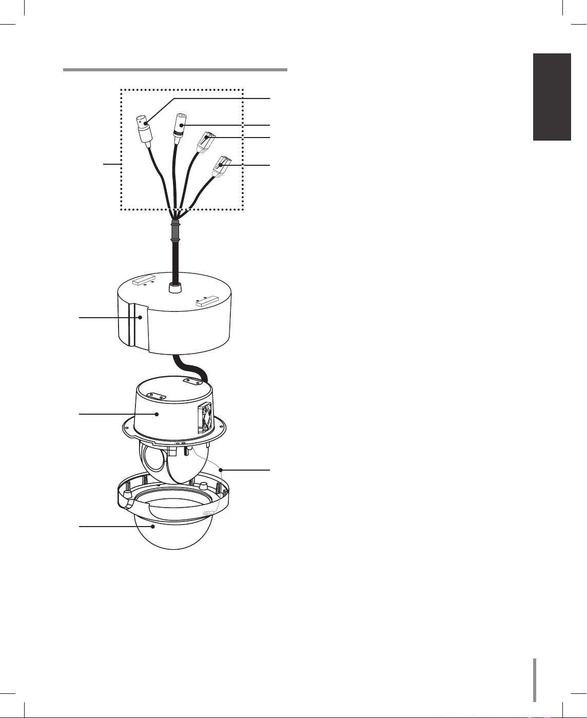
Identication of Camera
“A”
d
e
f
g
a
b
c
h
a Camera mounting bracket
b Dome camera body
c Dome cover assembly
d Video output cable with BNC connector
Connects with the video connector of the monitor.
e Power cable (DC 12V)
f Data Communication Port (RJ45) - RS-485 and
Alarm Input
g Data Communication Port (RJ45) - RS-485 and
Alarm Input
h Fall Prevention Wire
Be sure to hook the fall prevention wire into a
bracket.
Caution:
When you fix the dome cover to the dome camera
body, you must insert the wire in the dome camera
body. If not, the wire may obstruct the camera’s
moving.
“A”
Do not expose the power and data
cable to moisture, this may cause leakage into the housing and damage the camera. If
you must, please make sure that the connections
are sealed tightly. After installing the camera,
you should arrange the cables using the outlet
box to protect the cables.
LT303N-B.CSAUBLI_ENG_MFL620347257 7 2008.12.24 9:23:59 AM
8
Installation
Installation Precautions
The following steps of installation and connection work
should be done by qualified service personnel or system installers and should conform to all local codes.
Before you install and connect the camera, check and
prepare the required peripheral devices and cables.
Before you connect the camera, turn off all devices to
be connected, such as this camera and DVR.
Note:
Do not touch the dome cover’s window.
Camera Installation Location
Discuss the installation location for the camera with
your retailer, and select a place that is strong enough
for the installation.
Install the camera on a ceiling (concrete, etc.) at a
location that is sufficiently strong to support it.
Install the camera body on the foundation section
of the building or sections having sufficient bearing
strength.
Never install or use the camera in the following locations
Do not install it in areas exposed to direct sunlight
or rain.
Do not install the camera near the air outlet of an
air conditioner.
Near a swimming pool or other areas where chemicals are used.
Food preparation areas and other locations where
there are large amounts of steam vapor and oil,
in flammable atmospheres, other special environments.
Areas where radiation, X-rays, strong electric
waves, or magnetism is generated.
At sea, in coastal areas, or in areas where corrosive gas is being generated.
Areas outside of the allowable ambient operating
temperature range
When installing the camera on a ceiling of insufficient strength, reinforce the ceiling.
•
•
•
•
•
•
•
•
•
•
About Static Electricity Removal
Before installing the camera, touch a metal case or
other metallic parts with your hand to remove static
electricity from your body.
Do not install in areas subjected to high amounts of
humidity or dust.
Doing so may cause internal components to damage
more easily or malfunction.
Do not wire cables near power lines.
Tightening the Screws
Screws should be tightened sufficiently in accordance
with the materials and structure of the installation
location. After tightening the screws, visually inspect
them to make sure there is no unevenness and that
each screw is tight.
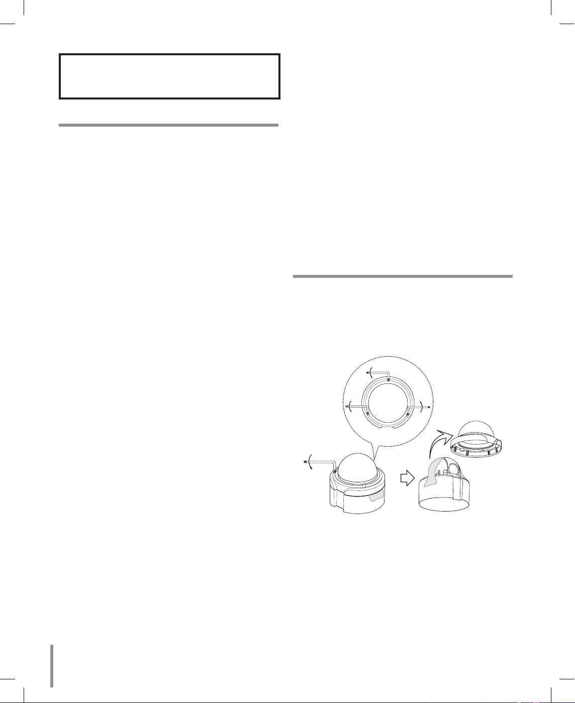
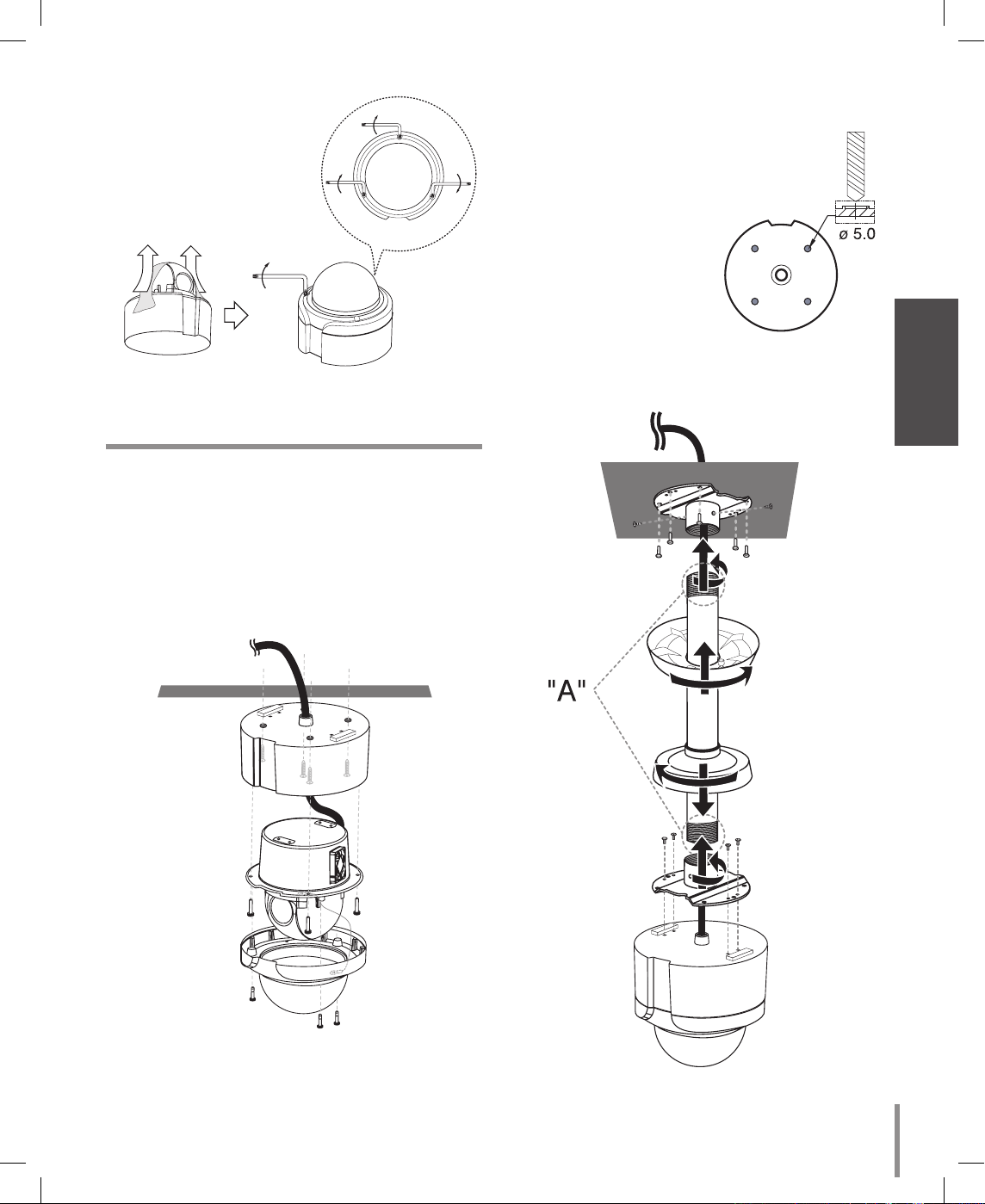
Removing the Protection Tape
Before using the camera, remove the protection tape.
Caution:
Remove the protection tape carefully.
1. Loosen the screws using the wrench and remove
the dome cover as shown below.
2. Remove the protection tape and attach the dome
cover.
LT303N-B.CSAUBLI_ENG_MFL620347258 8 2008.12.24 9:24:0 AM
9
Installation
Mounting the Camera
The figures show an example of the camera mounted
on a ceiling or wall with a locally procured bracket.
Note:
The camera have not been evaluated for wall or ceiling mounting.
Surface mount
Note:
When you install the camera to the ceiling mount,
you must drill a hole in the
camera body as shown
right. (ø5.0)
Pendant mount (Optional)
Install pipe and camera as shown below.
(B)
(A)
LT303N-B.CSAUBLI_ENG_MFL620347259 9 2008.12.24 9:24:4 AM
10
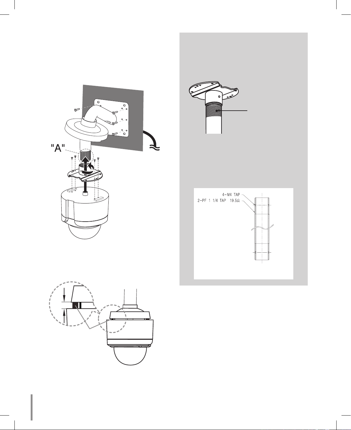
Wall mount (Optional)
Install the camera in the following order.
1. Drill holes on the wall where you want to install the
pipe.
2. Install the pipe and camera as shown below.
(B)
(A)
Note:
Do not remove the block (A) to keep the gap (B)
between the camera body and installation bracket.
(B)
(A)
How to install
“A”
Pipe threads should be clean and rust
free. Use a sealer (such as Teflon™
tape and silicone sealer) on the threads.
Add thread
sealing tape
Note:
The pipes and brackets for mounting are not
supplied.
Reference: Specifications of LG Standard
pipe.
LT303N-B.CSAUBLI_ENG_MFL6203472510 10 2008.12.24 9:24:6 AM
 Loading...