

Page 1

High Definition
Television Receiver
OWNER’S MANUAL
MODEL : LST-3100A
Before connecting, operating or adjusting this product,
please read this owner’s manual carefully and completely.
Page 2
2
Safety Precautions
WARNING
TO PREVENT FIRE OR SHOCK HAZARDS, DO NOT EXPOSE THIS PRODUCT TO RAIN OR MOISTURE.
WARNING: Do not install this equipment in a confined space such as a book case or similar unit.
CAUTION: TO PREVENT ELECTRIC SHOCK, MATCH WIDE BLADE OF PLUG TO WIDE SLOT AND FULLY INSERT.
ATTENTION: POUR ÉVITER LES CHOC ÉLECTRIQUES, INTRODUIRE LA LAME LA PLUS LARGE DE LA FICHE DANS LA
BORNE CORRESPONDANTE DE LA PRISE ET POUSSER JUSQU’AU FOND.
NOTE TO CABLE/TV INSTALLER
This reminder is provided to call the cable TV system installer’s attention to Article 820-40 of the National Electric Code (U.S.A.).
The code provides guidelines for proper grounding and, in particular, specifies that the cable ground shall be connected to the
grounding system of the building, as close to the point of the cable entry as practical.
REGULATORY INFORMATION: FCC Part 15
This product has been tested and found to comply with the limits for a Class B digital device, pursuant to Part 15 of the FCC
Rules. These limits are designed to provide reasonable protection against harmful interference when the product is operated in a
residential installation. This product generates, uses and can radiate radio frequency energy and, if not installed and used in
accordance with the instruction manual, may cause harmful interference to radio communications. However, there is no guarantee
that interference will not occur in a particular installation. If this product does cause harmful interference to radio or television
reception, which can be determined by turning the product off and on, the user is encouraged to try to correct the interference by
one or more of the following measures:
• Reorient or relocate the receiving antenna.
• Increase the separation between the product and receiver.
• Connect the product into an outlet on a circuit different from that to which the receiver is connected.
• Consult the dealer or an experienced radio/TV technician for help.
COMPLIANCE: The responsible party for this product’s compliance is:
Zenith Electronics Corporation, 2000 Millbrook Drive, Lincolnshire, IL, 60069, USA Phone: 1-847-941-8000
CAUTION
DO NOT ATTEMPT TO MODIFY THIS PRODUCT IN ANY WAY WITHOUT WRITTEN AUTHORIZATION FROM LG ELECTRONICS
CORPORATION. UNAUTHORIZED MODIFICATION COULD VOID THE USER’S AUTHORITY TO OPERATE THIS PRODUCT.
THIS EQUIPMENT IS INTENDED TO RECEIVE AND DECODE SIGNALS TRANSMITTED ACCORDING TO ATSC DIGITAL
TELEVISION STANDARD A/53, SPECIFICATION AND IS INTENDED TO BE USED WITH AN APPROPRIATE ANTENNA AND
DISPLAY DEVICE THAT YOU MUST PROVIDE.
CAUTION
RISK OF ELECTRIC SHOCK
DO NOT OPEN
THE LIGHTNING FLASH WITH ARROWHEAD SYMBOL, WITHIN AN EQUILATERAL TRIANGLE, IS INTENDED
TO ALERT THE USER TO THE PRESENCE OF UNINSULATED “DANGEROUS VOLTAGE” WITHIN THE PRODUCT’S ENCLOSURE THAT MAY BE OF SUFFICIENT MAGNITUDE TO CONSTITUTE A RISK OF ELECTRIC
SHOCK TO PERSONS.
THE EXCLAMATION POINT WITHIN AN EQUILATERAL TRIANGLE IS INTENDED TO ALERT THE USER TO THE
PRESENCE OF IMPORTANT OPERATING AND MAINTENANCE (SERVICING) INSTRUCTIONS IN THE LITERATURE ACCOMPANYING THE APPLIANCE.
CAUTION:
TO REDUCE THE RISK OF ELECTRIC SHOCK DO NOT REMOVE
COVER (OR BACK). NO USER SERVICEABLE PARTS INSIDE.
REFER TO QUALIFIED SERVICE PERSONNEL.
As an ENERGY STA R®Partner, LG
has determined that this product or product models meets
the ENERGY STA R®guidelines for
energy efficiency.
ENERGY STA R®is a U.S. registered mark.
Page 3

INTRODUCTION
3
IMPORTANT SAFETY INSTRUCTIONS
1. Read these instructions. - All these safety and oper-
ating instructions should be read before the product is
operated.
2. Keep these instructions. - The safety, operating and
use instructions should be retained for future reference.
3. Heed all warnings. - All warnings on the product and
in the operating instructions should be adhered to.
4. Follow all instructions. - All operating and use
instructions should be followed.
5. Do not use this apparatus near water. – For example: near a bath tub, wash bowl, kitchen sink, laundry
tub, in a wet basement; near a swimming pool; etc.
6. Clean only with dry cloth. – Unplug this product from
the wall outlet before cleaning. Do not use liquid
cleaners.
7.
Do not block any ventilation openings. Install in
accordance with the manufacturer’s instructions. -
Slots and openings in the cabinet are provided for
ventilation, to ensure reliable operation of the product,
and to protect it from over- heating. The openings
should never be blocked by placing the product on a
bed, sofa, rug or other similar surface. This product
should not be placed in a built-in installation such as a
bookcase or rack unless proper ventilation is provided
and the manufacturer’s instructions have been
adhered to.
8. Do not install near any heat sources such as radiators, heat registers, stoves, or other apparatus
(including amplifiers) that produce heat.
9.
Do not defeat the safety purpose of the polarized or
grounding-type plug. A polarized plug has two
blades with one wider than the other. A grounding
type plug has two blades and a third grounding
prong. The wide blade or the third prong are provided for your safety. If the provided plug does not
fit into your outlet, consult an electrician for
replacement of the obsolete outlet.
10. Protect the power cord from being walked on or
pinched particularly at plugs, convenience
receptacles, and the point where they exit from
the apparatus.
11. Only use attachments/accessories specified by
the manufacturer.
12. Use only the cart, stand, tripod, bracket, or table
specified by the manufacturer, or sold with apparatus. When a cart is used, use caution when
moving the cart/ apparatus combination to avoid
injury from tip-over.
13. Unplug this apparatus during lightning storms or
when unused for long periods of time.
14.
Refer all servicing to qualified service personnel.
Servicing is required when the apparatus has
been damaged in any way, such as powersupply cord or plug is damaged, liquid has been
spilled or objects have fallen into the apparatus,
the apparatus has been exposed to rain or moisture, does not operate normally, or has been
dropped.
CAUTION: PLEASE READ AND OBSERVE ALL WARNINGS AND INSTRUCTIONS IN THIS INSTALLATION
AND OPERATING GUIDE AND THOSE MARKED ON THE UNIT. RETAIN THIS GUIDE FOR
FUTURE REFERENCE.
This set has been designed and manufactured to assure personal safety. Improper use can result in electric shock
or fire hazard. The safeguards incorporated in this unit will protect you if you observe the following procedures for
installation, use, and servicing.
This unit does not contain any parts that can be repaired by the user.
DO NOT REMOVE THE CABINET COVER, OR YOU MAY BE EXPOSED TO DANGEROUS VOLTAGE. REFER
SERVICING TO QUALIFIED SERVICE PERSONNEL ONLY.
Page 4
4
Table of Contents
Introduction
Safety Precautions . . . . . . . . . . . . . . . . . . . . . . . . . 2
IMPORTANT SAFETY INSTRUCTIONS . . . . . . . . . . 3
Table of Contents . . . . . . . . . . . . . . . . . . . . . . . . . . 4
Front Panel Controls and Display Window . . . . . . 5
Remote Control Key Functions . . . . . . . . . . . . . . . 6
Unpacking HDTV Receiver and
Accessories/Connection Overview. . . . . . . . . . . . . 7
Connection Panel . . . . . . . . . . . . . . . . . . . . . . . . . . 8
INSTALLATION
Connections . . . . . . . . . . . . . . . . . . . . . . . . . . . . 9-16
Antenna Connections. . . . . . . . . . . . . . . . . . . . . . 9
Analog Monitor Connections . . . . . . . . . . . . . . . 10
HD Monitor Component (YPbPr) Connections . . 11
HD Monitor RGB Connections . . . . . . . . . . . . . . 12
HD Monitor DVI-HDTV Connections. . . . . . . . . . 13
VCR Connections . . . . . . . . . . . . . . . . . . . . . . . 14
Amplifier (Receiver) Connections . . . . . . . . . . . . 15
Setting the Display Format . . . . . . . . . . . . . . . . . . 16
MENU OPERATION
Initial Settings . . . . . . . . . . . . . . . . . . . . . . . . . . . . 17
General Operation . . . . . . . . . . . . . . . . . . . . . . . 17
Help Function . . . . . . . . . . . . . . . . . . . . . . . . . . 17
Setup Menu Options. . . . . . . . . . . . . . . . . . . . . 18-20
EZ Scan (Channel Search) . . . . . . . . . . . . . . . . 18
EZ Add . . . . . . . . . . . . . . . . . . . . . . . . . . . . . . . 18
Ch. Edit (Channel Edit) . . . . . . . . . . . . . . . . . . . 19
Manual Add . . . . . . . . . . . . . . . . . . . . . . . . . . . . 20
EZ Demo . . . . . . . . . . . . . . . . . . . . . . . . . . . . . . 20
Option Menu Options . . . . . . . . . . . . . . . . . . . . 21-24
Clock . . . . . . . . . . . . . . . . . . . . . . . . . . . . . . . . . 21
Menu Language. . . . . . . . . . . . . . . . . . . . . . . . . 21
Audio Language. . . . . . . . . . . . . . . . . . . . . . . . . 21
Aspect Ratio . . . . . . . . . . . . . . . . . . . . . . . . . . . 22
Choosing the Aspect Ratio using RATIO button . 23
Audio Output . . . . . . . . . . . . . . . . . . . . . . . . . . . 24
Audio Variable . . . . . . . . . . . . . . . . . . . . . . . . . . 24
Caption Menu Options . . . . . . . . . . . . . . . . . . . 25-27
DTV Caption . . . . . . . . . . . . . . . . . . . . . . . . . . . 25
DTV Caption Style . . . . . . . . . . . . . . . . . . . . . . . 26
Analog Caption . . . . . . . . . . . . . . . . . . . . . . . . . 27
Lock (Parental Control) Menu Options . . . . . . 28-32
Lock System . . . . . . . . . . . . . . . . . . . . . . . . . . . 28
Set Password . . . . . . . . . . . . . . . . . . . . . . . . . . 28
Block Ch. (Channel). . . . . . . . . . . . . . . . . . . . . . 29
Movie Rating . . . . . . . . . . . . . . . . . . . . . . . . . . . 30
TV Rating-Children . . . . . . . . . . . . . . . . . . . . . . 31
TV Rating-General . . . . . . . . . . . . . . . . . . . . . . . 32
GUIDE Options . . . . . . . . . . . . . . . . . . . . . . . . . 33-35
Program Guide . . . . . . . . . . . . . . . . . . . . . . . . . 33
Station Guide. . . . . . . . . . . . . . . . . . . . . . . . . . . 33
Information Displays . . . . . . . . . . . . . . . . . . . . . . . 34
Channel Banner Display. . . . . . . . . . . . . . . . . . . 34
Program Information Display . . . . . . . . . . . . . . . 35
NORMAL OPERATION
Program and Station Guide . . . . . . . . . . . . . . . 36-37
Normal Operation . . . . . . . . . . . . . . . . . . . . . . . . . 38
Channel Selection . . . . . . . . . . . . . . . . . . . . . . . 38
Volume Adjustment . . . . . . . . . . . . . . . . . . . . . . 38
Signal . . . . . . . . . . . . . . . . . . . . . . . . . . . . . . . . 38
Freeze . . . . . . . . . . . . . . . . . . . . . . . . . . . . . . . . 38
REFERENCE
Programming the Remote Control to Operate
Other Devices . . . . . . . . . . . . . . . . . . . . . . . . . . . . 39
Remote Control Codes for Other Devices . . . . 40-41
Troubleshooting . . . . . . . . . . . . . . . . . . . . . . . . . . 42
Specifications . . . . . . . . . . . . . . . . . . . . . . . . . . . . 43
Warranty . . . . . . . . . . . . . . . . . . . . . . . . . Back Cover
About the symbols for instructions
Indicates hazards likely to cause harm to the unit
itself or other material damage.
Indicates special operating features of this unit.
Indicates tips and hints for making the task easier.
Manufactured under license from Dolby Laboratories. Dolby,
and the double-D symbol are trademarks of Dolby
Laboratories. Confidential unpublished works. Copyright
1992-1997 Dolby Laboratories. All rights reserved.
Page 5
INTRODUCTION
5
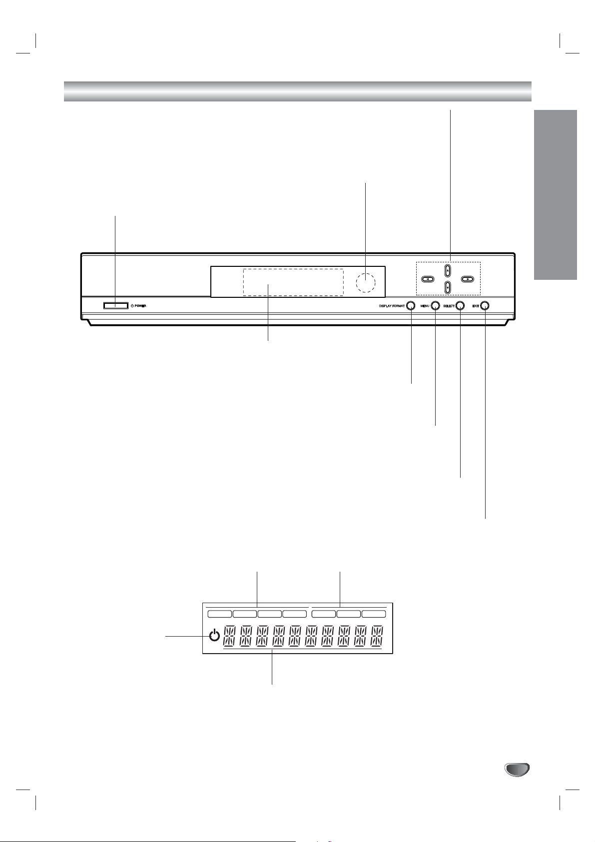
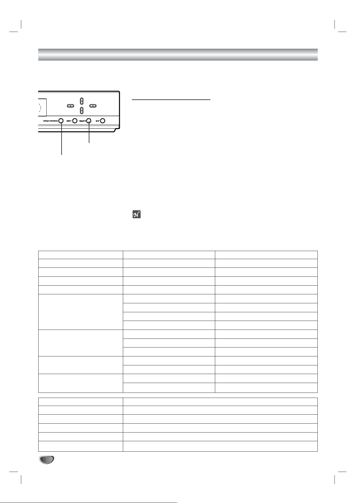
Front Panel Controls and Display Window
Remote Control Sensor
Receives signals from the remote control.
Display Window
EXIT
Clears all on-screen displays and returns to
normal viewing from any menu.
SELECT
If the main menu is displayed, pressing the SELECT button will activate
the selected MENU option. If the SELECT button is pressed while you
are in normal viewing, the channel banner will be displayed.
Arrow Buttons (3/4/1/2)
Allow you to navigate on-screen menus and to adjust the system settings and preferences.
Use the arrow keys to move to a menu option and then use the
SELECT
button to access it.
If no menu is displayed, the LEFT/RIGHT arrows control the volume setting and the
UP/DOWN arrows select channels.
MENU
Shows the main menu on the screen. You can return to
normal viewing by pressing the EXIT button.
DISPLAY FORMAT
Sets the output resolution to 1080i, 720p, 480p, or 480i formats and
chooses the correct display format for your TV. (Refer to page 16)
Power
Turns the HDTV Receiver on or off.
1080i
720p
480p
480i
DVI
RGB
YP
BPR
Standby indicator
Lights when the HDTV
Receiver is turned off.
Resolution indicator
Indicates output resolution.
Connection indicator
Indicates output connection.
Character indicators
Indicates channel number, volume level, etc.
Page 6
6
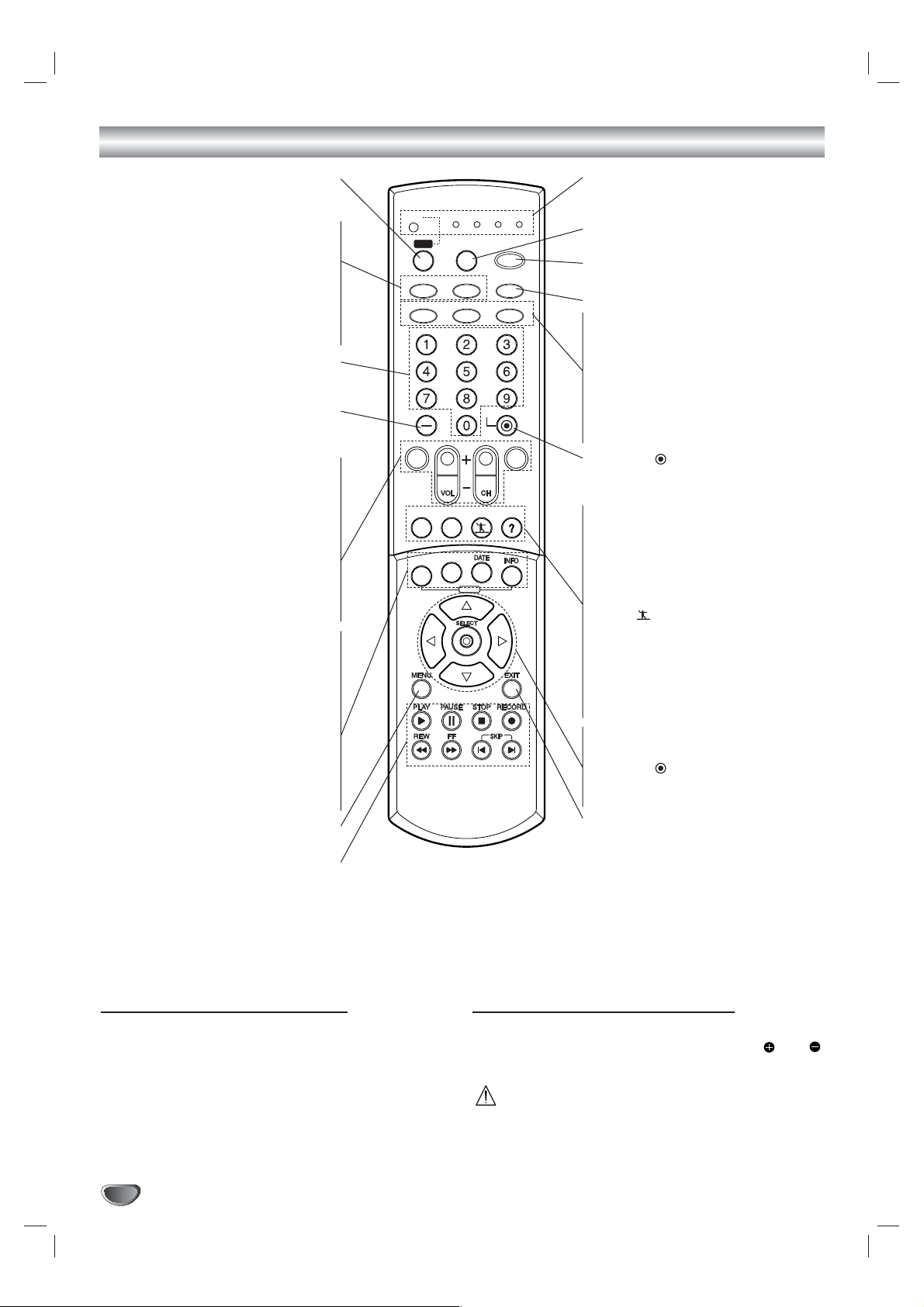
Remote Control Key Functions
GUIDE
MODE
SELECT
WER
TION
STB
Sets operational mode of remote control to
the HDTV Receiver
.
TV/INPUT
To select the TV’s source (Tuner or AUX
A/V input).
ez ADD
Automatically adds new channels (digital)
available through the antenna inputs
except memorized channels already in
the channel list.
Numbers
Chooses channels and enters program-
ming information.
Dash (-)
Enters a channel number for multiple pro-
gram channels such as 2-1, 2-2, etc.
MUTE
Turns sound ON and OFF.
VOL (Volume) (+/–)
Changes volume.
CH (Channel) (+/–), PG UP/DN
Selects a memorized channels. Pressing
the PG UP/DN buttons pages through the
Program Guide or Channel Edit menu.
FLASHBK
Returns to the last channel viewed.
PROGRAM
Brings up the Program Guide.
STATION
Brings up the Station Guide.
DATE
Changes the date of the Program or
Station Guide when the Program or
Station Guide is displayed.
INFO
Shows the current station and program
information on the screen.
MENU
Accesses or closes main menu.
Component Control Buttons
Provides control for DVD players, VCRs,
and similar components.
Mode Indicator
Indicates the remote control operational
mode.
MODE
Selects operational mode of remote control.
POWER
Turns the HDTV Receiver ON and OFF.
This button is not available.
AUDIO
Selects program’s audio language options
if available.
CC
Selects caption mode if available.
SIGNAL
Shows the signal strength of the current
channel.
SELECT ( )
Completes the channel number input and
promptly tunes to selected channel.
RATIO
Changes the picture aspect ratio.
FREEZE
Freezes the current image. Pressing the
button once again returns the image to
live video.
SURF ( )
Tunes to your surf channels or to scan the
guide.
HELP (?)
You can see the help description of a
menu option while that menu is displayed
by pressing the HELP (?) button.
Arrow Buttons (
3/4/1/2
)
Selects options in a menu.
SELECT ( )
Completes the channel number input and
promptly tunes to selected channel.
EXIT
Removes all on-screen displays and
returns to TV viewing from any menu.
Remote Control Operation Range
Point the remote control at the remote sensor and press
the buttons.
Distance: About 23 ft (7 m) from the front of the
remote sensor.
Angle: About 30° in each direction of the front of the
remote sensor.
Remote Control Battery Installation
Remove the battery cover on the rear of the remote
control, and insert two batteries (size AA) with and
aligned correctly. Reinstall cover.
Caution
Do not mix old and new batteries. Never mix different
types of batteries (standard, alkaline, etc.).
STB
TV VCR DVD AUX
STB
MODE
POWER
TV/INPUT
ez ADD
AUDIO CC SIGNAL
*
SELECT
PG UP
PG DN
FLASHBKMUTE
FREEZE SURF HELP
RATIO
PROGRAM
STSTATION
GUIDE
Page 7
7
INTRODUCTION
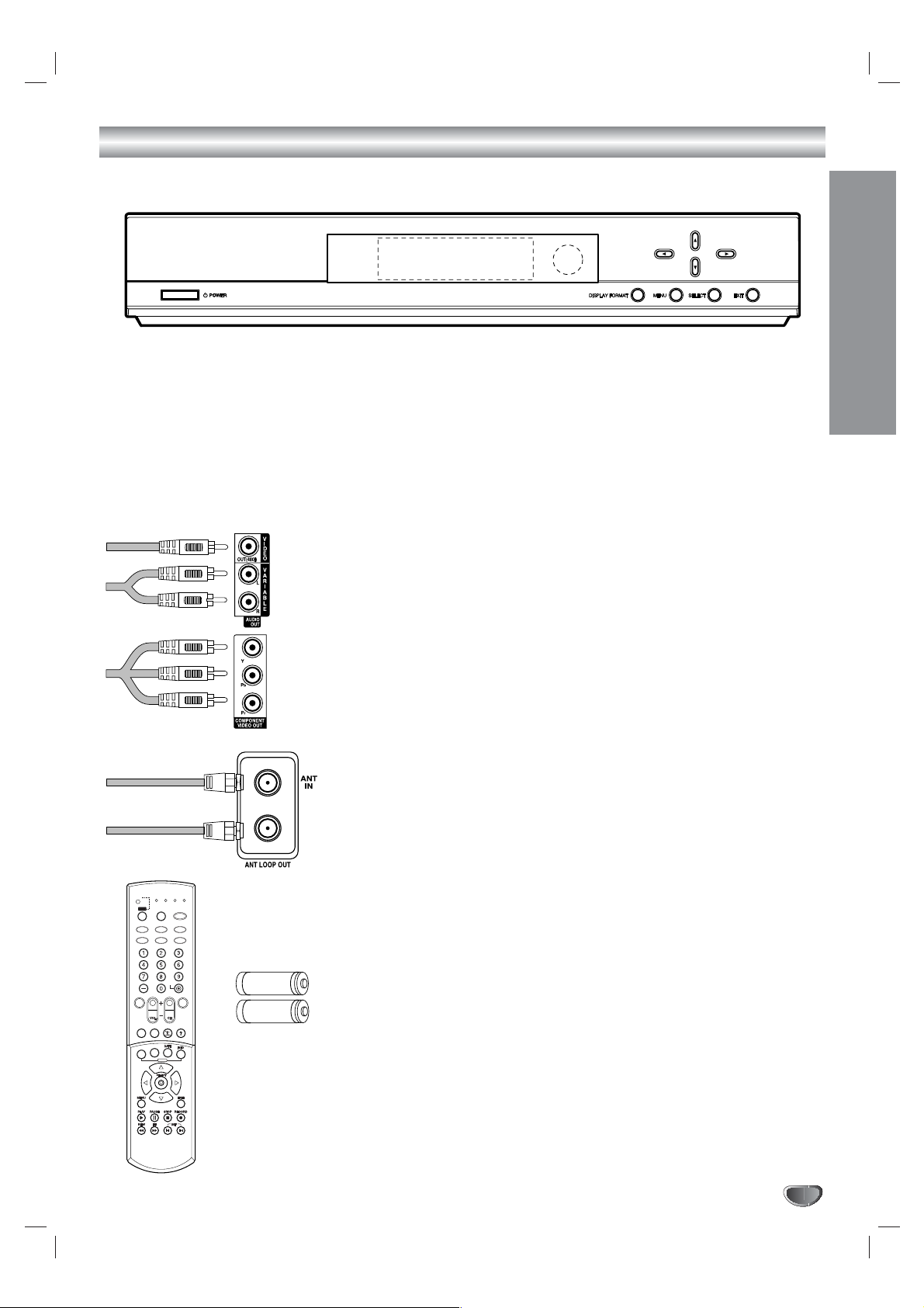
Unpacking HDTV Receiver and Accessories/Connection Overview
Audio/Video Jacks and Cables
The Audio/Video jacks provide excellent picture and sound quality. They are
used for making most Audio/Video connections between components. The
Audio/Video jacks may be color coded (yellow for video, red for right audio,
and white for left audio). If your component has only one input for audio
(mono), connect it to the left (white L/mono) audio jack on the HDTV
Receiver.
Component Out Jacks and Cables
Component Cables are used to connect the HDTV Receiver to an industry
standard YPbPr compatible HD Monitor (green for Y, blue for Pb, and red
for Pr). Remember to connect the left and right audio cables. The YPbPr
Component jacks carry only the picture signals, not the sound.
ANT LOOP OUT Jack, and RF Cable
ANT LOOP OUT provides an RF connection between the HDTV Receiver
and the TV and provides the signal of ANT IN jack to TV.
Remote Control
In addition to the HDTV Receiver, the remote control can be programmed to
control many other devices.
Batteries
To install the batteries, slide open the battery compartment and insert the
two AA batteries provided.
Make sure you have received all the accessories listed below with the High Definition Television Receiver.
STB
GUIDE
STB
MODE
TV/INPUT
UDIOCCCC
SIGNAL
ez ADD
WER
VCR
UX
FLASHBK
MUTE
TIO
OGRAM
FREEZE
SURF
HELP
PG DN
PG UP
High Definition Television Receiver
The HDTV Receiver is capable of receiving signals from cable and/or over-the-air antenna
sources and sending the signals to your TV.
Included with the Receiver are the following accessories.
Audio Cable Video Cable
Component(YPbPr) Cable RF Cable
Remote Control 2 AA Batteries
STB
TV/INPUT
TV VCR
DVD AUX
STB
MODE
POPOWER
ez ADD
*
AUDIO
SIGNAL
SELECT
FLASHBK
MUTE
PG UP
PG DN
RARATIO
FREEZE
SURF
PRPROGRAM
HELP
STATION
GUIDE
AA
AA
Page 8
8
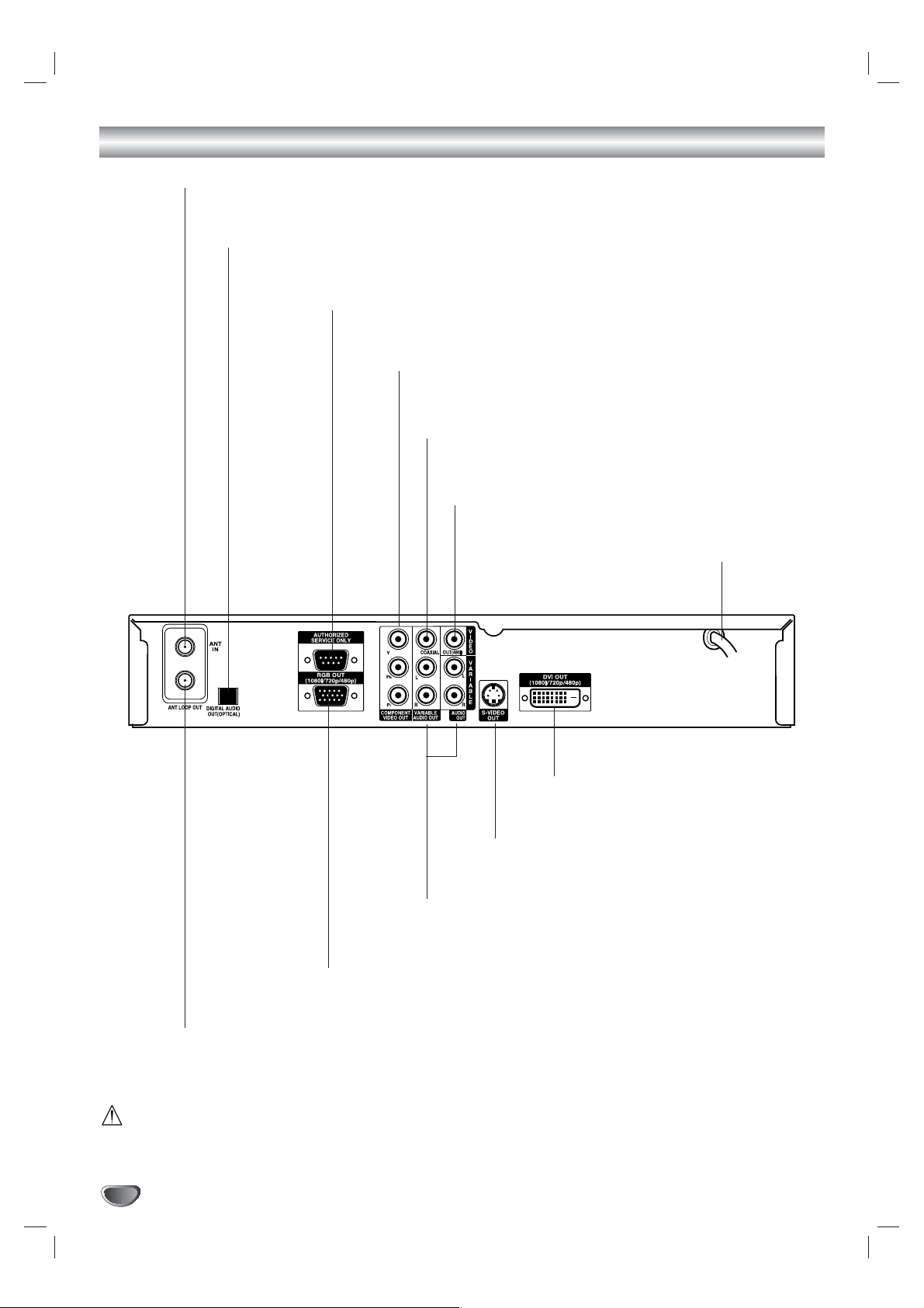
Connection Panel Overview
Do not touch the inner pins of the jacks on the rear panel.
Electrostatic discharge may cause permanent damage to the unit.
AC Power Cord
Plug into the power source.
ANT LOOP OUT
RF output to TV’s “Antenna In” jack or other devices.
OPTICAL (Digital audio out jack)
Connect to digital (optical) audio equipment.
COAXIAL (Digital audio out jack)
Connect to digital (coaxial) audio equipment.
VIDEO OUT
Connect to a TV with video inputs.
COMPONENT VIDEO OUT
Connect to a TV with YPbPr inputs.
AUTHORIZED SERVICE ONLY
Is used only for authorized service purposes.
ANT IN
Connect to HDTV signal source; external/internal antenna.
S-VIDEO OUT
Connect to a TV with S-Video inputs.
DVI OUT
Connect to a TV with DVI connector.
Variable AUDIO OUT (Left/Right)
Connect to a TV, amplifier, receiver or stereo system.
RGB OUT
Connect to a TV with RGB inputs.
Page 9
INSTALLATION
9
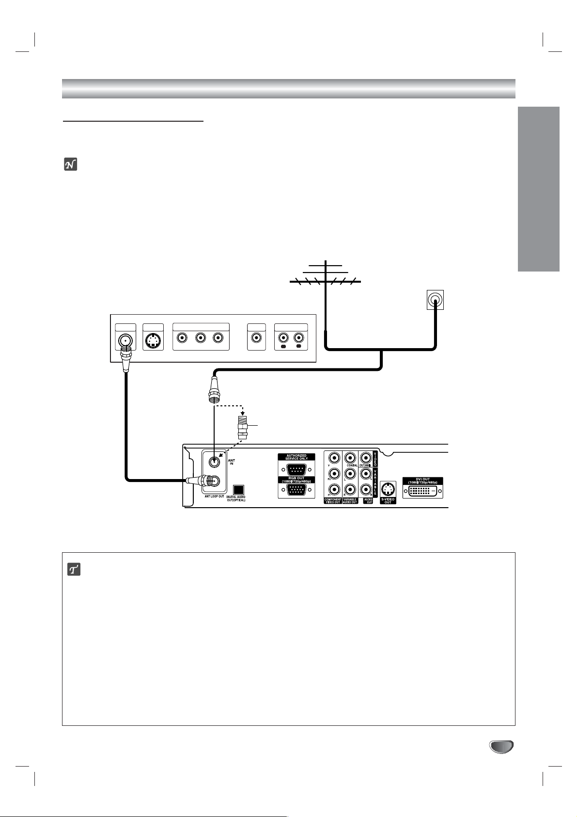
Connections
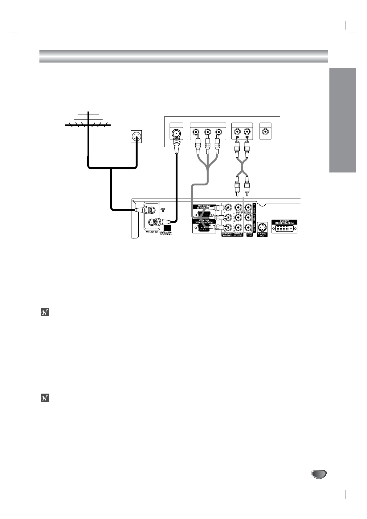
Antenna Connections
1
Connect the “Antenna” to the “ANT IN” jack on the HDTV Receiver using a coaxial RF cable.
ote
There might be some areas where the signal strength could be too high. If so, you may need to connect the
antenna to an attenuator. Screw the attenuator onto the “ANT IN” jack.
2
Connect the “ANT LOOP OUT” jack on the HDTV Receiver to the “Antenna In” jack on your TV using a coaxial
RF cable.
ip
Before Connecting Your Antenna
During initial installation and setup of your HDTV Receiver, you may need to install a 10 dB attenuator to the
Antenna input “ANT IN” on the LST-3100A. The LST-3100A is a high performance, high-gain system intended for
operation under normal and weak signal conditions, providing the best reception with its optimum gain. However,
there might be some reception areas where the signal strength is too high (e.g. due to close proximity to an undesirable signal or transmitter), so you need an attenuator that lowers the incoming signal strength (from the undesirable transmitter) to more normal levels. This 10 dB attenuator should be used only in a reception area where the
undesired signal strength is too high. One of the possible symptoms would be that after your program/channel
search, your HDTV receiver does not find all the local digital terrestrial channels available in your area. (You can
find HDTV channels/content information for your local broadcast area by going to Zenith website
“WWW.ZENITH.COM” and clicking on “HDTV Program Schedule” under HDTV.) Please make sure that before
deciding to use an optional attenuator device, you are using an appropriate and properly aligned UHF/VHF RF terrestrial antenna.
Antenna
Cable TV
Wall Jack Panel
TV or Other Device Connection Panel
S-VIDEO
ANTENNA
INPUT
INPUT
COMPONENT VIDEO INPUT
Pr
Y
Pb
VIDEO
INPUT
AUDIO INPUT
R
L
L
OR
OR
Attenuator
(Not supplied)
HDTV Receiver Connection Panel
Page 10
Connections (Continued)
10
Display Formats Overview
• The HDTV Tuner offers various display formats and multiple video outputs. When the HDTV Tuner is connected
to A/V systems, the HDTV Tuner can provide video signal formats 1080i, 720p, 480p, and 480i.
• 1080i, 720p, 480p, and 480i modes are available for component video (YPbPr) outputs.
• 1080i, 720p, and 480p modes are available for RGB and DVI outputs.
• 480i mode is available for VIDEO, S-VIDEO, and COMPONENT VIDEO outputs.
• The HDTV Tuner has two digital audio outputs; Dolby Digital 5.1 and PCM. The HDTV Tuner sends out a digital
audio signal to OPTICAL and COAXIAL audio outputs when digital broadcasts are being received by the HDTV
Tuner.
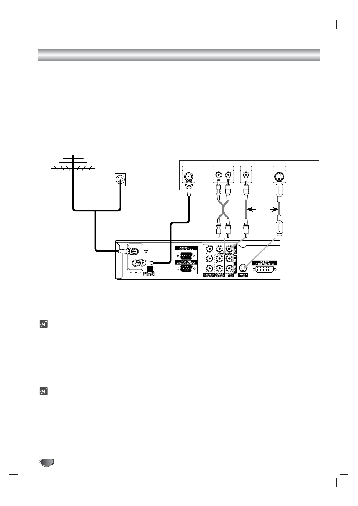
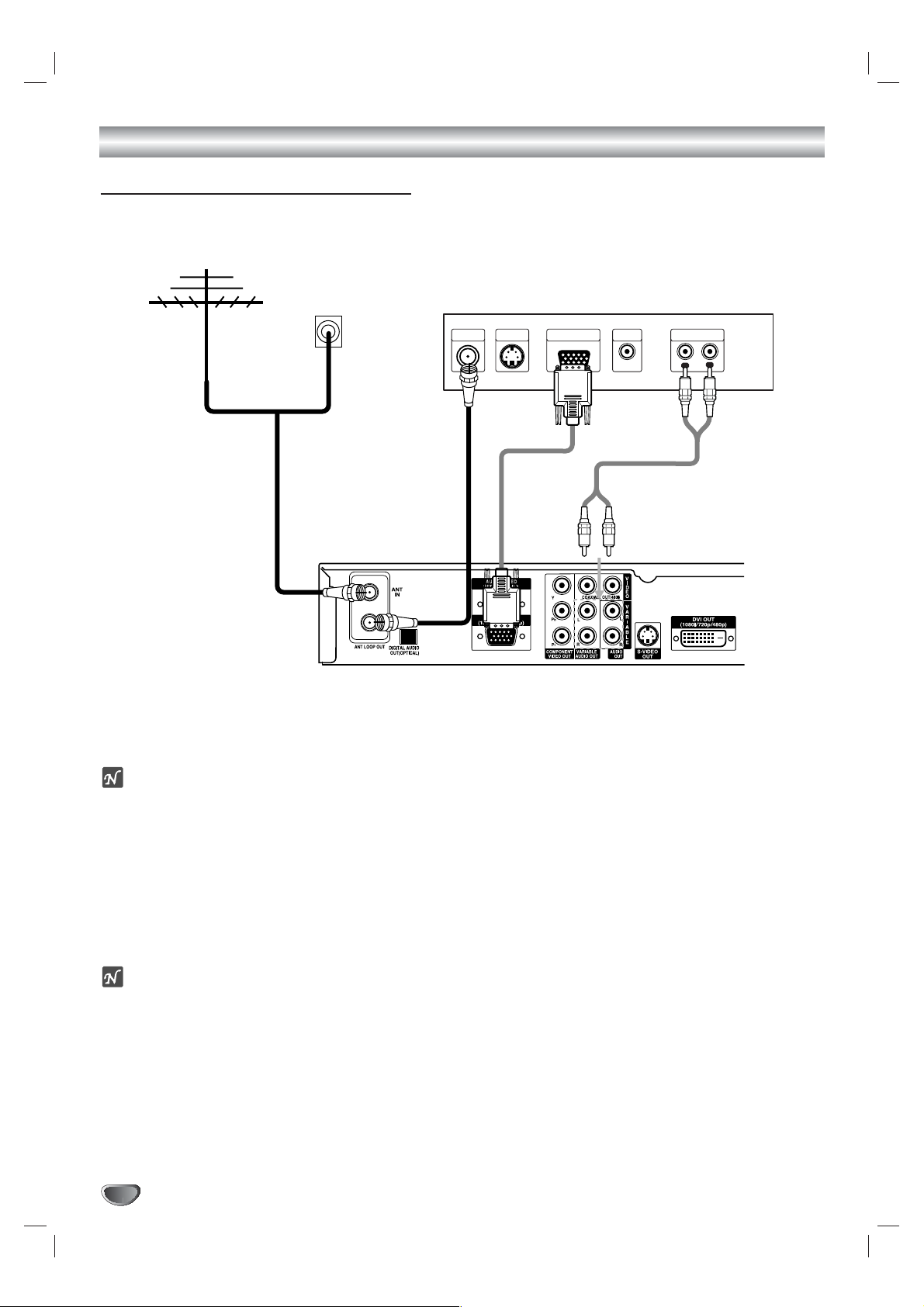
Analog Monitor Connections
1
Connect the “Antenna/Cable” to the “ANT IN” jack on the HDTV Receiver using a coaxial RF cable.
ote
There might be some areas where the signal strength could be too high. If so, you may need to connect the
antenna to an attenuator. Screw the attenuator onto the “ANT IN” jack. (Refer to page 9.)
2
Connect the “ANT LOOP OUT” jack on the HDTV Receiver to the “Antenna In” jack on your TV using a coaxial
RF cable.
3
Connect the “AUDIO OUT” and “VIDEO OUT” jacks on the HDTV Receiver to the “A/V IN” jacks on your TV
using RCA-type cables. If your TV is equipped with an S-Video jack, use the S-VIDEO OUT jack.
(The Output Selection must be set to YPbPr, refer to Setting the Display Format on page 16)
ote
These connections are only useable if the display format settings are set to 480i and YPbPr. (Refer to page 16.)
Antenna
Cable TV
Wall Jack Panel
TV Connection Panel
ANTENNA
INPUT
AUDIO INPUT
L
R
VIDEO
INPUT
S-VIDEO
INPUT
L
OR
To AUDIO OUT
OR
HDTV Receiver Connection Panel
Page 11
INSTALLATION
11
Connections (Continued)
HD Monitor Component (YPbPr) Connections
1
Connect the “Antenna/Cable” to the “ANT IN” jack on the HDTV Receiver using a coaxial RF cable.
ote
There might be some areas where the signal strength could be too high. If so, you may need to connect the
antenna to an attenuator. Screw the attenuator onto the “ANT IN” jack. (Refer to page 9.)
2
Connect the “ANT LOOP OUT” jack on the HDTV Receiver to the “Antenna In” jack on your TV using a coaxial
RF cable.
3
Connect the “COMPONENT OUT” jacks on the HDTV Receiver to the “COMPONENT IN” jacks of your TV
using RCA-type cables. (The Output Selection must be set to YPbPr, refer to Setting the Display Format on
page 16)
4
Connect the L/R “AUDIO OUT” jacks on the HDTV Receiver to the L/R “AUDIO IN” jacks on your TV using
RCA-type cables.
ote
1080i, 720p, 480p, and 480i modes are available for component video (YPbPr) outputs.
Antenna
Cable TV
Wall Jack Panel
OR
HD Ready TV Connection Panel
ANTENNA
INPUT
COMPONENT VIDEO INPUT
Pr
Y
Pb
AUDIO INPUT
L
R
VIDEO
INPUT
To AUDIO OUT
HDTV Receiver Connection Panel
Page 12
12
Connections (Continued)
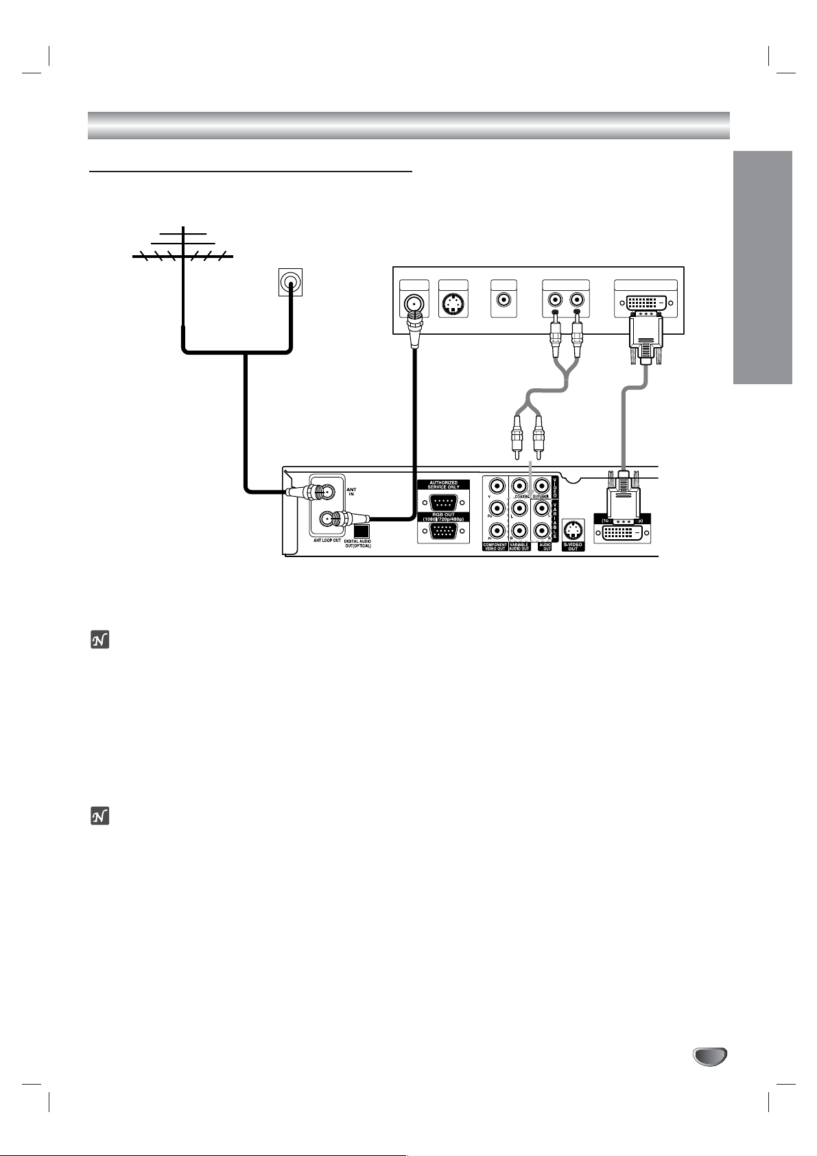
HD Monitor RGB Connections
1
1
Connect the “Antenna/Cable” to the “ANT IN” jack on the HDTV Receiver using a coaxial RF cable.
ote
There might be some areas where the signal strength could be too high. If so, you may need to connect the
antenna to an attenuator. Screw the attenuator onto the “ANT IN” jack. (Refer to page 9.)
2
Connect the “ANT LOOP OUT” jack on the HDTV Receiver to the “Antenna In” jack on your TV using a coaxial
RF cable.
3
Connect the “RGB OUT” jack on the HDTV Receiver to the “RGB IN” jack of your TV using VGA-type connector. (The Output Selection must be set to RGB, refer to Setting the Display Format on page 16)
4
Connect the L/R “AUDIO OUT” jacks on the HDTV Receiver to the L/R “AUDIO IN” jacks on your TV using
RCA-type cables.
ote
1080i, 720p, and 480p modes are available for RGB outputs.
Antenna
Cable TV
Wall Jack Panel
OR
HD Ready TV Connection Panel
S-VIDEO
ANTENNA
INPUT
INPUT
VIDEO
INPUT
To AUDIO OUT
AUDIO INPUTRGB INPUT
R
L
HDTV Receiver Connection Panel
Page 13
Connections (Continued)
INSTALLATION
13
HD Monitor DVI-HDTV Connections
1
1
Connect the “Antenna/Cable” to the “ANT IN” jack on the HDTV Receiver using a coaxial RF cable.
ote
There might be some areas where the signal strength could be too high. If so, you may need to connect the
antenna to an attenuator. Screw the attenuator onto the “ANT IN” jack. (Refer to page 9.)
2
Connect the “ANT LOOP OUT” jack on the HDTV Receiver to the “Antenna In” jack on your TV using a coaxial
RF cable.
3
Connect the “DVI OUT” jack on the HDTV Receiver to the “DVI IN” jack of your TV using DVI-D type connector.
(The Output Selection must be set to DVI, refer to Setting the Display Format on page 16)
4
Connect the L/R “AUDIO OUT” jacks on the HDTV Receiver to the L/R “AUDIO IN” jacks on your TV using
RCA-type cables.
ote
• 1080i, 720p, and 480p modes are available for DVI outputs.
• A DVI-HDTV input is one that is compliant with EIA-861 and HDCP specifications. Check your TV or monitor's
user manual to find out if the TV or monitor's DVI input is compliant with these specifications.
• Some HD Monitors designed for PC applications using DVI-D may not work with this connection.
Antenna
Cable TV
Wall Jack Panel
OR
HD Ready TV Connection Panel
ANTENNA
INPUT
S-VIDEO
INPUT
To AUDIO OUT
VIDEO
INPUT
AUDIO INPUT DVI-HDTV INPUT
R
L
HDTV Receiver Connection Panel
Page 14
14
Connections (Continued)
VCR Connections
Connect the L/R “AUDIO OUT” jacks and “VIDEO OUT” jack on the HDTV Receiver to the “A/V in” jacks on your
VCR using RCA-type cables. (If your VCR is equipped with an S-Video jack, use the “S-Video” jack.)
Caution
If 480i display format is selected, the VCR will record an onscreen display onto the tape during recording if:
the channel is changed with CH (+/–)
the sound level is adjusted with VOL (+/–)
or by pressing the SELECT button, etc.
VCR Connection Panel
AUDIO INPUT
L
To AUDIO OUT
VIDEO
INPUT
R
L
HDTV Receiver Connection Panel
Page 15

INSTALLATION
15
Connections (Continued)
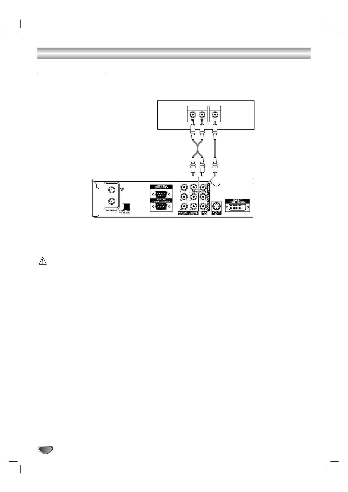
Amplifier (Receiver) Connections
Connecting to an amplifier equipped with two channel analog stereo or Dolby Surround
Connect the Left and Right AUDIO OUT jacks on the HDTV Receiver to the audio left and right in jacks on your
amplifier, receiver, or stereo system, using the supplied audio cables.
Connecting to an amplifier equipped with two channel digital stereo (PCM) or to an Audio/ Video
receiver equipped with a multi-channel decoder (Dolby Digital™)
Connect one of the HDTV Receiver’s DIGITAL AUDIO OUT jacks (OPTICAL or COAXIAL) to the corresponding
input jack on your amplifier. Use an optional digital (optical or coaxial) audio cable.
Digital Multi-channel sound
A digital multi-channel connection provides the best sound quality. For this you need a multi-channel Audio/Video
receiver that supports one or more of the audio formats supported by your HDTV Receiver (Dolby Digital). Check
the receiver manual and the logos on the front of the receiver.
Amplifier (Receiver) Connection Panel
OPTICAL COAXIAL
L
R
AUDIO INPUTDIGITAL INPUT
OR
HDTV Receiver Connection Panel
Page 16
Setting the Display Format
16
The HDTV Receiver provides several display formats. The DISPLAY FORMAT button on the front panel changes the output connector and resolution.
The output resolution may be converted from the original broadcast format.
Display Format Setting
1
Press DISPLAY FORMAT once on the front panel.
The current output signal will appear in the display window.
2
Depending on the type of monitor that the HDTV Receiver is connected to, press DISPLAY FORMAT repeatedly on the front panel to
select desired output connector. (YPbPr, RGB, or DVI)
3
Press SELECT on the front panel to confirm your selection of the
output connector.
The current output resolution will appear in the display window.
4
Depending on the type of monitor that the HDTV Receiver is connected to, press DISPLAY FORMAT repeatedly on the front panel to
select desired output resolution. (1080i, 720p, 480p, 480i, native,
variable 1, variable 2, or variable 3)
5
Press SELECT on the front panel to confirm your selection of the
output resolution.
DIsplay Format setting is finished
ote
You can exit Display Format Setting mode by pressing EXIT on the front
panel.
Display Format modes Input Signal format Output Signal format
1080i all formats 1080i
720p all formats 720p
480p all formats 480p
480i all formats 480i
native 1080i 1080i
720p 720p
480p 480p
480i 480i(Component), 480p (RGB, DVI)
variable 1 1080i 1080i
720p 720p
480p/480i 480p
variable 2 1080i/720p 1080i
480p/480i 480p
variable 3 1080i/720p 720p
480p/480i 480p
OUTPUT CONNECTION AVAILABLE FORMATS
COMPONENT OUT 1080i/720p/480p/480i/native/variable 1/variable 2/variable 3
RGB OUT 1080i/720p/480p/native/variable 1/variable 2/variable 3
DVI OUT 1080i/720p/480p/native/variable 1/variable 2/variable 3
VIDEO OUT All formats converted to 480i
S-VIDEO OUT All formats converted to 480i
DISPLAY FORMAT
SELECT
Page 17

MENU OPERATION
17
Initial Settings
In this menu system, there are several ways to customize the settings provided. Most menus consist of three levels to set up the options, but some
require greater depth for the variety of settings. If you press the MENU button, only the first and second level of the menu system will appear on the TV
screen. The third level can be displayed by pressing (SELECT). If a menu
has more than three levels, the pop-up dialogue box will be displayed as the
fourth or fifth level. For navigating the menu levels, you will see “2” on the
right side of the menu label to help you go to the next level.
To show and remove the Menu:
Press the MENU button on the remote control to display the menu. A second
press of the MENU button or a press of the EXIT button will take you back to
TV viewing.
To go to the next level:
Press “ ” (or “2”) on the remote control.
To go back to the previous level:
Press MENU (or “1”) on the remote control.
General Operation
1
Press MENU.
The main menu will appear.
2
Use3/4to select the desired menu option.
3
While the desired menu option is selected, press 2or (SELECT)
to move to the second level.
4
Use3/4to select the second menu option.
5
Press2or (SELECT) to move to the third level.
Some menu options require additional steps.
6
Press MENU to exit the Setup menu.
Help Function
The Help feature is designed to let you understand each function of the
Menu in an easy and convenient way. As you navigate through the Menu,
press HELP (?) button on your remote control if you want information about
the highlighted option. The information will be displayed on the right side of
the highlighted option.
TION
HELP (?) button
RATIO
FREEZE SURF HELP
STSTATION
PROGRAM
Page 18

18
Setup Menu Options
EZ Scan (Channel Search)
Automatically finds all channels (digital) available using the ‘Ant In’ source,
and stores all the active channels found on the channel list. Inactive or weak
channels may not appear on the list. In that case, add missing channels
manually with the Manual Add menu. The channel list created here can be
seen in the Ch. Edit menu.
1
Press MENU to display the on-screen menu.
2
Select the SETUP menu using 3/4then press (SELECT) or 2to
move to the second level.
3
Select the EZ Scan using 3/4then press (SELECT) or 2.
ote
If the Lock System is set to On, a password is required to gain access to the
EZ Scan menu. Follow step 2 as shown for the Lock System on page 28.
4
Select the signal source (DTV or CADTV).
DTV is for over-the-air antenna reception.
CADTV is for cable subscribers.
otes
• If you select CADTV, select a cable band (STD, HRC, or IRC). Ask your
cable service provider about cable band.
• In most cases you can search channels correctly by selecting STD cable
band. Try the other bands if you cannot find any channels.
• Some scrambled channels may not be stored.
5
Press (SELECT).
The channel search process begins. You can stop the process by pressing (SELECT), MENU or EXIT.
6
When channel search is complete, the lowest channel number
found appears on the TV screen.
EZ Add
Automatically adds new channels (digital) available through the antenna
inputs except memorized channels already in the channel list.
1
Press MENU to display the on-screen menu.
2
Select the SETUP menu using 3/4then press (SELECT) or 2to
move to the second level.
3
Select the EZ Add using 3/4then press (SELECT) or 2.
EZ Add channel search process begins. You can stop the process by
pressing (SELECT), MENU or EXIT.
4
When EZ Add channel search is complete, the lowest channel number found appears on the TV screen.
ip
You can also start EZ Add channel search by pressing ez ADD then
(SELECT) button on the remote control.
ez ADD button
TV/INPUT
AUDIO CC SIGNAL
ez ADD
*
Page 19

MENU OPERATION
19
Setup Menu Options (Continued)
Ch. Edit (Channel Edit)
Channel Edit allows you to add or delete channels from the channel list in
memory manually and create your own surf list of favorite channels. Press
SURF ( ) on the remote control when a channel is highlighted.
1
Press MENU to display the on-screen menu.
2
Select the SETUP menu using 3/4then press (SELECT) or 2to
move to the second level.
3
Select the Ch. Edit using 3/4then press (SELECT) or 2.
Channel Edit menu appears.
To move one by one:
Use 3 / 4 to move by one step on the channel editing menu.
To move page by page:
Use PG UP or PG DN button to move to the next or previous page on
the channel editing menu.
To add or delete a channel:
Press (SELECT) to add or delete the channel on the channel editing
menu.
To create a surf list:
Press SURF ( ) to add the channel a Surf channel.
4
Press MENU to return to the previous menu or press EXIT on the
remote control to return to TV viewing.
ote
Deleted channels can not be selected using the CH (+/–) buttons.
Page 20

Setup Menu Options (Continued)
20
Manual Channel Add/Delete
This feature allows you to add or delete channels manually while monitoring
signal strength.
1
Press MENU to display the on-screen menu.
2
Select the SETUP menu using 3/4then press (SELECT) or 2to
move to the second level.
3
Select the Manual Add using 3/4then press (SELECT) or 2.
Manual Add menu appears.
4
Select a channel to add or delete using 3/4or the numbered buttons with the Manual Add menu.
5
Press (SELECT) to confirm your selection.
6
Repeat steps 4-5 to add or delete additional channels with the
Manual Add menu.
ote
You can only add the selected channel if the signal strength is shown.
7
Press MENU to return to the previous menu or press EXIT on the
remote control to return to TV viewing.
EZ Demo
Shows you how to navigate through the on-screen menus available on the
HDTV Receiver.
1
Press MENU to display the on-screen menu.
2
Select the SETUP menu using 3/4then press (SELECT) or 2to
move to the second level.
3
Select EZ Demo using 3/4then press (SELECT) or 2to start EZ
Demo.
4
Press any button on the remote control to return to TV viewing.
Page 21

MENU OPERATION
21
Option Menu Options
Clock
Enables the user to adjust the time zone. Normally, your clock is set using
signals transmitted by DTV stations. Choosing your time zone sets the current time automatically.
1
Press MENU to display the on-screen menu.
2
Select the OPTION menu using 3/4then press (SELECT) or 2.
3
Use3/4to select the Clock option then press 2or (SELECT) to
move to the third level.
4
Use1/2to set Time Zone: (Atlantic, Eastern, Central, Mountain,
Pacific, Alaska, Hawaii, New F.land)
5
Press MENU to return to the previous menu or press EXIT on the
remote control to return to TV viewing.
ote
•
The clock can not be set in cable DTV band.
• There are cases where the TV station does not send, or sends wrong date and/or
time information causing the HDTV Receiver to set an incorrect time.
• You have no way to manually set the clock.
Menu Language
Select a language for the menu.
1
Follow Steps 1-2 as above (Clock).
2
Select the Menu Language option using 3/4then press
(SELECT) or 2.
3
Select the desired language using 3/4 then press (SELECT).
4
Press MENU to return to the previous menu or press EXIT on the
remote control to return to TV viewing.
Audio Language
Digital channels sometimes provide multiple audio tracks, often in a different
language. You can set default audio language with the Audio Language menu.
1
Follow Steps 1-2 as above (Clock).
2
Select the Audio Language option using 3/4then press
(SELECT) or 2.
3
Select the desired language using 3/4 then press (SELECT).
4
Press MENU to return to the previous menu or press EXIT on the
remote control to return to TV viewing.
ip
• If provided by broadcaster, you can also select a different audio language
while viewing TV by pressing AUDIO repeatedly.
• When multiple audio tracks are available, the audio icon ( ) appears on
the program information display or Program guide. You can select one of
the other languages with the AUDIO button.
AUDIO button
AUDIO CC SIGNAL
Page 22

22
Option Menu Options (Continued)
Aspect Ratio
Lets you choose the screen format. To view a picture with a wide (16:9)
aspect ratio at 480i or 480p mode output format, you can choose Letter Box,
Cropped, or Squeezed. To view a picture with a normal (4:3) aspect ratio at
720p or 1080i mode output format, you can choose Normal, Wide, Horizon,
Zoom, or Cinema Zoom.
1
Press MENU.
The main menu appears.
2
Use3/4to select the OPTION menu then press 2or (SELECT)
to move to the second level.
3
Use3/4to select the Aspect Ratio option.
4
Press2or (SELECT) to move to the third level.
5
Use3/4to select an option then press (SELECT) to confirm
your selection.
6
Press MENU to return to the previous menu or press EXIT on the
remote control to return to TV viewing.
Letter Box Cropped Squeezed
Normal Wide Horizon Zoom Cinema Zoom
otes
• If program format is High Definition (16:9) and the display format selected
is 1080i or 720p, the Aspect Ratio is set to Wide .
• If program format is Standard Definition (4:3) and the display format
selected is 480p or 480i, the Aspect Ratio is set to Squeezed.
ip
While watching TV, you can change the picture aspect ratio using RATIO on
the remote control. To view a high definition picture with 480i or 480p format
setting, use the RATIO button on the remote control to change the wide
mode in the following cycle: Letterbox, Cropped, to Squeezed.
To view a standard definition picture with 720p or 1080i format setting, use
the RATIO button on the remote control to change the wide mode in the following cycle: Normal, Wide, Horizon, Zoom, to Cinema Zoom. (Refer to
Choosing the Aspect Ratio on next page).
Options to view a picture with a
wide (16:9) aspect ratio at 480i
or 480p mode output format.
Options to view a picture with a
normal (4:3) aspect ratio at 720p
or 1080i mode output format.
Cut Off
TION
RATIO button
Cinema Zoom mode
Use to adjust zooming. The
picture will be enlarged like the
cinema screen.
RATIO
FREEZE SURF HELP
STATION
PROGRAM
Page 23

MENU OPERATION
23
Option Menu Options (Continued)
Choosing the Aspect Ratio using RATIO button
Modes for viewing high definition content (16:9) when output format is 480i or 480p Mode:
Letter Box
Use for a picture with an original 16:9 aspect ratio (in a wide format). Letterbox mode will shrink the picture to fill
the screen, with black/gray (or blank) bars appearing at the top and bottom of the screen.
Cropped
Use for a picture filling the entire screen by cropping (removing) the left and right portions of the picture.
Squeezed
Use for a full picture filling the entire screen with no black/gray bars. The picture in a 16:9 format will be horizontally
adjusted or squeezed to fit the 4:3 ratio monitor. This setting can also be useful when used with 16:9 aspect ratio
monitors or with 4:3 aspect ratio monitors that have a “16:9 enhancement” feature.
Modes for viewing standard definition content (4:3) when output format is 720p or 1080i Mode:
Normal
Use for a picture with an original 4:3 aspect ratio on your 16:9 monitor, with black/gray bars appearing at the left
and right sides.
Wide
Use for a picture adjusted horizontally (in a linear proportion) to fill the entire screen.
Horizon
Use to adjust a picture in a non-linear proportion (more at both sides) to create a spectacular view.
Zoom
Use when you want to fill the entire screen with no black/gray bars appearing. The image will be altered both horizontally (stretched) and vertically (cropped). The top and bottom portions of the picture will be cut.
Cinema Zoom
Use to adjust zooming. The picture will be enlarged like the cinema screen.
Modes for temporarily viewing high definition content (16:9) when output format is 720p or 1080i Mode:
Standard
Choose when you want to view a picture with no adjustment.
Expand
Choose when you want to view a picture in the 16:9 ratio size. The picture will be horizontally adjusted or extended
to fit 16:9 ratio. Left and right portions of the picture will not be shown.
Shrink
Choose when you want to view a picture in the 4:3 ratio size. The picture will be horizontally adjusted or squeezed
to fit 4:3 ratio. Black or gray bars will show at the left and right side.
Program Format Output Format Available Aspect Ratios
HD(720p/1080i) 16:9 HD(720p/1080i) 16:9 Three temporary Aspect Ratio controls
(Standard, Expanded, Shrink)
HD(720p/1080i) 16:9 SD(480i/p) 4:3 Letter Box, Cropped, Squeezed
SD(480i/p) 4:3 HD(720p/1080i) 16:9 Five Aspect Ratio controls
(Normal, Wide, Horizon, Zoom, Cinema Zoom)
SD(480i/p) 4:3 SD(480i/p) 4:3 No Adjustment Options
Aspect Ratio Summary
Page 24

24
Option Menu Options (Continued)
Audio Output
Sets the HDTV Receiver’s digital Audio Output according to the type of audio
system you use.
1
Press MENU to display the on-screen menu.
2
Select the OPTION menu using 3/4then press (SELECT) or 2.
3
Select the Audio Output option using 3/4then press
(SELECT) or 2.
4
Select the desired audio output using 3/4 then press
(SELECT).
Dolby Digital: Select “Dolby Digital” if you connected the HDTV
Receiver’s DIGITAL OUT jack to a Dolby Digital decoder (or an amplifier or other equipment with a Dolby Digital decoder).
PCM: Select when the HDTV Receiver’s DIGITAL OUT jack is connected to a 2-channel digital stereo amplifier.
5
Press MENU to return to the previous menu or press EXIT on the
remote control to return to TV viewing.
Audio Variable
If the audio variable menu is set to On, audio volume can be increased/
decreased with by pressing VOL (+/–) on the remote control or 1/2 on the
front panel. If set to off, audio volume can not be controlled by HDTV receiver.
1
Press MENU to display the on-screen menu.
2
Select the OPTION menu using 3/4then press (SELECT) or 2.
3
Select Audio Variable using 3/4then press (SELECT) or 2.
4
Select an Audio Variable option (On or Off) using 3/4 then press
(SELECT).
5
Press MENU to return to the previous menu or press EXIT on the
remote control to return to TV viewing.
ote
Before setting the Audio Variable to Off, make sure that you have turned down the
TV’s volume to the minimum. Otherwise, sudden high volume sound may cause hearing or speaker damage.
Page 25

MENU OPERATION
25
Caption Menu Options
DTV Caption
Selects a default Caption language.
The caption language options are English, French, and Spanish. Use the
menu to select a language. If the selected language is not available on the
current program, the caption language for the program is not displayed.
Options are:
Off: DTV Caption is not displayed.
English: English is selected for DTV captions.
French: French is selected for DTV captions.
Spanish: Spanish is selectedfor DTV captions.
otes
• DTV Caption (Standard EIA /CEA 708) will appear only if provided by the
broadcaster.
• If DTV and Analog Captions are received simultaneously, you can only
select DTV Caption.
ip
• If available, you can also select a caption language while viewing TV,
press CC repeatedly.
• If captions are available, the DTV caption icon ( ) appears on the pro-
gram information display, Program guide, or Station guide to indicate that
you can select one of those caption options with the CC button. The caption icon will not appear on the program information display or Program
guide for analog caption.
Page 26

26
Caption Menu Options (Continued)
DTV Caption Style
Selects DTV Captions appearance menu options.
Style
Use caption feature defaults as provided by the program or customize
caption appearance with the Custom menu options.
Set By Program: Default text provided by a broadcaster is shown when
captions appear.
Custom: Customized text is shown when captions appear.
Size
Selects the font size for captions.
Standard: The standard text size is used for the caption display (15 pixels).
Large: The large text size is used for the caption display (21 pixels).
Small: The small text size is used for the caption display (11 pixels).
Font
Selects the font type for caption.
Txt. (Text) Color
Selects the font color for caption.
Txt. (Text) Opacity
Selects the font opacity for caption.
Solid: The text is solid (without any transparency).
Flash: The text blinks twice a second.
Translucent: The text is translucent.
Transparent: The text is transparent (In this case, whatever the color is,
the color does not affect the caption display).
Edge Color
Selects the edge color for caption (If the edge type is selected as None, the
edge color does not have any effect on the caption display).
Edge Type
Selects the edge type for caption.
None: The text has no edge.
Raised: The text is raised.
Depressed: The text is depressed.
Uniform: The text has a uniform edge.
Left Shadow: The text has a left-shadow edge.
Right Shadow: The text has a right-shadow edge.
Bg. (Background) Color
Selects the background color for caption.
Bg. (Background) Opacity
Selects the background opacity for caption.
Solid: The text background color is solid (without any transparency).
Flash: The text background color blinks twice a second.
Translucent: The text background color is translucent.
Transparent: The text background color is transparent (In this case, what-
ever the background color is, the color does not affect the caption).
Page 27

MENU OPERATION
27
Analog Caption
Allows you to select a mode for displaying Analog Caption Data. In the
Analog Caption Service, Caption 1-4 display program’s dialog, and Text 1-4
display data service information.
ote
Analog Captions will appear if they are provided by the broadcaster.
Off
Analog Caption is not displayed.
Caption 1
Caption 1 is the primary caption service that synchronizes the captioning language with the sound, used by most broadcasters. Captioning is displayed
in the same language as the program’s dialog.
Caption 2
Caption 2 is the special non-synchronous caption service that does not need
to be in sync with the sound and may provide simplified captioning, which is
usually delayed.
Caption 3
Caption 3 serves as an alternate captioning service channel. Captioning is
often a secondary language translation such as French, Spanish, simplified
English or displayed at a slower rate.
Caption 4
Caption 4 is another special non-synchronous caption service that does not
need to be in sync with the sound and may provide simplified captioning,
usually delayed.
Text 1 - 4
Text 1-4 usually displays information on the lower portion of the screen and
is used for a data service, generally not program related.
ip
If available, press CC repeatedly to select a caption language while viewing
TV.
ote
If DTV and Analog Caption are received simultaneously, you can only select
DTV Captions, analog captions will not appear.
Caption Menu Options (Continued)
Page 28

28
Lock (Parental Control) Menu Options
Lock System
Allows you to set up specific channels and ratings through blocking
schemes. Also allows you to activate or disable all of the lock schemes previously set up. A password is required to gain access to the LOCK menus.
When the Lock System is set to Off, the Channel and Program Rating are
not effective.
1
Press MENU.
The main menu appears.
2
Use3/4to select the LOCK then press 2or (SELECT) to move
to the second level.
When you have not entered a password yet;
Enter “0000” password using the numbered buttons to create a personal
4-digit security password.
When you have already entered a password;
Enter the 4-digit password using the numbered buttons to confirm the
personal 4-digit security password.
3
Use3/4to select the Lock System option.
4
Press2or (SELECT) to move to the third level.
5
Use3/4to select an option (On or Off) then press (SELECT) to
confirm your selection.
6
Press MENU to return to the previous menu or press EXIT on the
remote control to return to TV viewing.
Set Password
Changes the password.
1
Follow steps 1-2 as shown above (Lock System).
2
Use3/4to select the Set Password option.
3
Press2or (SELECT) to move to the third level.
4
Enter the new 4-digit code.
5
Enter the same code again.
6
Press MENU to return to the previous menu or press EXIT on the
remote control to return to TV viewing.
Page 29

MENU OPERATION
29
Lock (Parental Control) Menu Options (Continued)
Block Ch. (Channel)
Blocks any channel that you do not want to view or that you do not want your
kids to watch. If you tune in a blocked channel, a black screen with a pop-up
box will appear. This menu can override Channel Edit menu settings (page
19).
1
Follow Steps 1-2 as shown for the Lock System on page 28.
2
Use3/4to select the Block Ch. (channel).
The channel list screen appears.
To move one-by-one:
Use 3 / 4 to move by one step on the block channel menu.
To move page-by-page:
Use PG UP or PG DN button to move to the next or previous page on
the block channel menu.
To lock or unlock a channel:
Press (SELECT) to block or unblock the channel on the block channel
menu.
The mark will appear to the right of the station name to indicate the
blocked channel.
3
Repeat step 2 to block or unblock additional channels in the channel list menu.
4
Press MENU to return to the previous menu or press EXIT on the
remote control to return to TV viewing.
Page 30

Lock (Parental Control) Menu Options (Continued)
30
Movie Rating
Blocks movies according to the movie ratings so children cannot view certain
movies. You can set the ratings to block out all the movies with ratings above
a specified level. Keep in mind that the movie ratings apply only to movies
shown on TV, not TV programs such as soap operas.
1
Follow Steps 1-2 as shown for the Lock System on page 28.
2
Use3/4to select the Movie Rating option.
3
Press2or (SELECT) to move to the third level.
4
Use3/4to select a rating then press (SELECT) to confirm your
selection.
All Block: All programs with a rating are blocked.
G (General Audiences): Content is not offensive to most viewers.
PG (Parental Guidance Suggested): Content is such that parents may
not want their children to view the program.
PG-13 (Parental Guidance Suggested): Program is inappropriate for
preteens, with a greater degree of offensive material than a PG rated
program.
R (Restricted viewing): Not for children under age 17. Strong elements
of sex and/or violence.
NC-17 (Restricted Viewing): Not for children under age 17 under any
circumstances. Strong sexual content.
X (Hard Core Films): Same as NC-17 rating.
5
Press MENU to return to the previous menu or press EXIT on the
remote control to return to TV viewing.
Page 31

MENU OPERATION
31
Lock (Parental Control) Menu Options (Continued)
TV Rating-Children
Keeps children from watching certain children’s TV programs according to the
ratings limit set. This rating applies only to TV programs for children. Unless
you block TV programs intended for mature audiences in the TV Rating –
General menu, your children could view those programs.
1
Follow Steps 1-2 as shown for the Lock System on page 28.
2
Use3/4to select the TV Rating-Children option.
3
Press2or (SELECT) to move to the third level.
4
Use3/4to select the Age or Fantasy Violence option then press
2
or (SELECT).
Age: Selection applies regardless of content category of rating.
Fantasy Violence: Selection applies if TV programs include rating for
Fantasy Violence.
5
Use3/4to select a rating then press (SELECT) to confirm your
selection.
All Block: All programs with a rating are blocked.
TV-Y: All Children. This program is designed to be appropriate for all
children.
TV-Y7: Directed to Older Children. This program is designed for children
age 7 and above.
6
Press MENU to return to the previous menu or press EXIT on the
remote control to return to TV viewing.
Page 32
32
Lock (Parental Control) Menu Options (Continued)
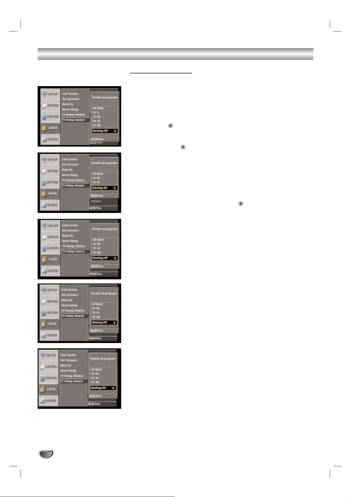
TV Rating-General
Blocks TV programs that you or your family may not wish to watch, based on
the rating scheme set.
1
Follow Steps 1-2 as shown for the Lock System on page 28.
2
Use3/4to select the TV Rating-General option.
3
Press2or (SELECT) to move to the third level.
4
Use3/4to select the Age, Dialogue, Language, Sex, or Violence
then press 2or (SELECT).
Age: Selection applies regardless of content category of rating.
Dialogue: Selection applies if TV programs have rating for Dialogue.
Language: Selection applies if TV programs have rating for Language.
Sex: Selection applies if TV programs have rating for Sex.
Violence: Selection applies if TV programs have rating for Violence.
5
Use3/4to select a rating then press (SELECT) to confirm your
selection.
All Block: All programs with a ratings are blocked.
TV-G: General Audience. Most parents would find this program suitable
for all ages.
TV-PG: Parental Guidance Suggested. This program contains material
that parents may find unsuitable for younger children.
TV-14: Parents Strongly Cautioned. This program contains some
materials that many parents would find unsuitable for children under
14 years of age.
TV-MA: Mature Audience Only. This program is specifically designed to
be viewed by adults and therefore may be unsuitable for children
under 17.
6
Press MENU to return to the previous menu or press EXIT on the
remote control to return to TV viewing.
Page 33

MENU OPERATION
33
GUIDE Options
Program Guide
The Program Guide contains schedule and program information for all
channels.
It also provides local over-the-air channels information including conventional
digital channels.
Use the Program Guide to find programs easily and conveniently and view
schedule and descriptive program information by Time and General classifications.
ip
You can also display the Program Guide by pressing PROGRAM button on
the remote control. Refer to Program and Station Guide on pages 36-37 for
detailed information.
1
Press MENU.
The main menu appears.
2
Use3/4to select the GUIDE menu then press 2or (SELECT) to
move to the second level.
3
Use3/4to select the Program Guide option.
4
Press2or (SELECT) to display the Program Guide.
5
Use1/2/3/4to select a program then press (SELECT) to get
more information for the program.
6
Press EXIT to return to TV viewing.
ote
The information for program guide and time may differ depending on the TV
station.
Station Guide
Use the Station Guide to find programs easily and conveniently and view
schedule and descriptive program information with channel number.
ip
You can also display the Station Guide by pressing the STATION button on
the remote control. Refer to Program and Station Guide on pages 36-37 for
detailed information.
1
Follow Steps 1-2 as shown as above.
2
Use3/4to select the Station Guide option.
3
Press2or (SELECT) to display the Station Guide.
4
Use1/2/3/4to select a program then press (SELECT) to get
more information for the program.
5
Press EXIT to return to TV viewing.
Page 34

34
Information Displays
Channel Banner Display
The Channel Banner appears whenever you tune to a new channel or press
the (SELECT) button on the remote control while viewing a program.
1
Press (SELECT) while watching a program
The Channel Banner appears on the TV screen (Channel number, audio,
station name, and current time).
• The Channel Banner can be displayed on the TV screen for a
moment.
a) Channel Number
Displays the current channel number.
b) Dolby Digital
Indicates audio track is Dolby Digital.
c) Digital picture grade
Displays the digital picture grade such as HD (High Definition) or SD
(Standard Definition).
d) Station name
Displays the station name of the current channel.
e) Block information
Displays the block information such as no signal, rating blocked,
channel blocked, audio only or scrambled.
f) Time
Displays the current time.
2
Press (SELECT) again while the Channel Banner is displayed.
The Channel Banner disappears from the TV screen.
otes
• Station name and clock are displayed only if they are set up by broadcast.
• The scrambled channel may not be able to see the program.
abc
e
d
f
Page 35

Information Displays (Continued)
NORMAL OPERATION
35
Program Information Display
The Program Information appears whenever you press the INFO button on
the remote control while viewing a program.
1
Press INFO while watching a program
Program Information appears on the TV screen.
a) Program title
Indicates title of current program.
(see page 37).
b) Date
Displays the current date.
c) Start Time, End Time and elapsed indication
Displays the start time, end time and the elapsed time indicator bar
for the current program.
d) Time
Shows current time.
e) Channel Number
Displays the current channel number.
f) Dolby Digital
Indicates audio track is Dolby Digital.
g) Digital Picture Grade
Displays the digital picture grade such as HD (High Definition) or SD
(Standard Definition).
h) Station Name
Displays the station name of the current channel.
i) Extended text message Icon ( )
Indicates that there is an Extended Text Message available to provide
detailed descriptions of the program (see page 37).
j) Multiple Audio icon ( )
Channels sometimes provide multiple audio tracks, often in a different
language. When multiple audio tracks are available, the Alternate
Audio icon changes its appearance to indicate that you can select one
of those other audio tracks with the AUDIO button.
k) DTV Caption Icon ( )
Indicates that the current program contains digital closed caption data
service.
l) Wide Icon ( )
Indicates that the current program is shown in wide picture format.
m)Content Advisory Icon ( )
Content Advisory data is used for the parental guide control to block
programs that are beyond predefined rating criteria set by users. This
icon means that the current program contains content advisory data,
and displays rating value of program.
2
Press INFO or EXIT while the Program Information is displayed.
The Program Information disappears from the TV screen.
ote
Station name and clock are displayed only if they are set up by broadcast.
abc d efg
ijk lm
h
Page 36

36
Program and Station Guide
The Program and Station Guide contains schedule and program information
for all channels. They also provide local over-the-air channels information
including conventional digital channels. Use the Program and Station Guide
to find programs easily and conveniently and to view schedule and descriptive program information for the channels.
To Display the Program or Station Guide
- Press the PROGRAM or STATION button on your remote control.
or
- Press the MENU button on the remote control and select the GUIDE
menu. Guide options will appear. Choose the Program or Station Guide
option [MENU → GUIDE → Program Guide (or Station Guide)]
To Exit the Program or Station Guide
Press the EXIT button to return to the last channel you tuned to.
To Navigate through programs on the Guides
The Program and Station Guide are operated based on a simple
straightforward “Highlight and Select” process.
1. Use 1 / 2 / 3 / 4 on your remote control to navigate the guide screen.
2. Press SELECT to select or execute the highlighted menu or function (see
page 37).
The on-screen guide shows you program listings for five channels within
one and half hour time slot. For example: 6:00-7:30. In order to view a list
of future programs or other channels, you may continuously press 1 / 2 /
3 / 4 to scroll horizontally or vertically. This may take a while to reach a
specific channel or program, if the channel or program is listed far from
the currently highlighted program. The Program and Station Guide thus
offers you shortcuts to minimize your effort in navigating channels and
time slots.
Line Scrolling
You can reach other time slots or channels that are currently hidden from
the screen using the arrow buttons “1/2/3/4”. Move horizontally to
reach other channels and move vertically to reach other time slots on the
Station Guide.
Date Scrolling
When the Program or Station Guide is displayed, you can also change the
date of the Program Guide by pressing the DATE button then use 3/4to
select date.
Page Scrolling (Program Guide only)
You can move faster through channels by scrolling page-by-page with the
PG UP or PG DN buttons on the remote control. Each button stroke
scrolls one page up or down.
To update the guide information (Guide Scan)
You can update the guide information by pressing SURF ( ).
The Guide Scan will update the guide information through all available
channels; this may take a few minutes.
Program Guide
Station Guide
Guide Scan
GUIDE
TION
STATION button
SURF( ) button
DATE button
INFO button
Arrow buttons
PROGRAM button
RATIO
FREEZE SURF HELP
STATION
PROGRAM
GUIDE
Page 37

Program and Station Guide (Continued)
NORMAL OPERATION
37
To show all Information available on the Extended Text Message
Pressing the SELECT button will display the full information window about
the highlighted program with Extended Text Message Icon (see page 35).
Depending on the broadcaster and service provider, the Extended Text
Message may include actor and role relationships, original material, production studio, the date on which the program was first shown, and so on.
ips
• If you select a TV program currently being broadcast, “Confirm” appears
on the bottom of the full information window. Press (SELECT) to disappear the full information window.
• If you select a past or future TV program on currently tuned channel, “OK”
appears on the bottom of the full information window. Press (SELECT)
to remove the full information window.
• You can view hidden information on the full information window.
Use3/4to scroll vertically.
To Tune to another channel on the Full Information window
You can also tune in other channels on the Full Information window.
If you select a TV program that is not on the currently tuned channel, “Do
you want to watch this Channel” message appears on the bottom of the full
information window. Select “YES” then (SELECT) to tune to the channel of
the selected program. Select “NO” then (SELECT) to remove the full information window.
Page 38

38
Normal Operation
Channel Selection
You can select a channel as shown below.
Number and – (dash) buttons (on the remote control)
Use Number (0-9) and – (dash) buttons to select a channel directly.
FLASHBK button (on the remote control)
Press to return to the previous channel you viewed. For example, if the
DTV Receiver is tuned to channel 55 and then you change to channel 56,
pressing FLASHBK will return to channel 55.
SURF ( ) button (on the remote control)
Press to scroll through your favorite channels.
CH +/– buttons (on the remote control) or 3 / 4 (on the front panel)
Use CH +/– on the remote control or 3 / 4 on the front panel to cycle the
HDTV Receiver through the channels in memory.
Volume Adjustment
Adjusts the volume of analog audio out on HDTV Receiver. You must set
Audio Variable to On in the OPTION menu to use the Volume Adjustment.
See page 24.
VOL +/– buttons (on the remote control) or 1/2(on the front panel)
Use VOL +/– on the remote control or 1/2on the front panel to adjust
the volume for analog audio out on the HDTV Receiver.
MUTE (on the remote control)
Press MUTE to turn off the volume for analog audio out on the HDTV
Receiver.
otes
• Before setting Audio Variable to Off, make sure that you have turned down the TV’s
volume to the minimum. Otherwise, sudden high volume sound may cause hearing
or speaker damage.
• The volume of digital audio out on HDTV Receiver can not be adjusted on the
HDTV Receiver front panel.
Signal
Shows the signal strength bar for incoming signal to help you adjust the
antenna to the correct position for your location. You can view the signal
strength bar by pressing SIGNAL on the remote control.
ip
Refer to www.antennaweb.org for antenna position.
AntennaWeb.org, will help you determine the proper outdoor antenna to use
in order to receive television channels that are broadcast locally.
Freeze
Pressing the FREEZE button freezes the current image. Pressing the
FREEZE button once again returns the image to live video.
ote
The frozen image returns to live video after 5 minutes.
SIGNAL button
SELECT
PG DN
PG UP
CH +/– buttons
SURF ( ) button
Number buttons
– (dash) button
FLASHBK button
TION
FREEZE button
PG DN
PG UP
VOL +/– buttons
MUTE button
FREEZE SURF HELP
RATIO
SELECT
PG UP
PG DN
PG UP
PG DN
FLASHBKMUTE
FLASHBKMUTE
AUDIO CC SIGNAL
RATIO
FREEZE SURF HELP
STSTATION
PROGRAM
Page 39

REFERENCE
39
Programming the Remote Control to Operate Other Devices
The HDTV Receiver remote control is a multi-brand or universal remote control that can be programmed to operate most remote-controllable devices
from other manufacturers.
ote
The remote control may not be able to control all models of other brands.
1
Test your remote control.
To find out whether your remote control can operate a device without
programming, turn on the device such as a VCR and select the corresponding mode (VCR) by pressing MODE on the remote control while
pointing at the device. Use the POWER and CH +/– buttons to see if the
device responds properly. If not, the remote control requires programming.
2
Turn on the device to be programmed. Then select the corresponding mode (VCR, AUX, TV, DVD or STB) by pressing MODE on the
remote control.
3
Press the POWER button and the MUTE button simultaneously.
The remote control is now ready to program the code for the device.
4
There are two ways to find the correct code for the device.
First, if you press the CH + buttons repeatedly, the codes will change
one at-a-time. If the right code is found, the device will turn off.
Second, enter the code number using the number buttons on the
remote control. The right code numbers for the corresponding device
can be found on the following pages. If the code is correct, the device
will turn off.
5
Press the EXIT button to store the programming code.
6
Test the remote control functions to see if the device responds
properly. If not, repeat from step 2.
GUIDE
SELECT
WER
TION
STB
TV VCR DVD AUX
STB
TV/INPUT
AUDIO CC SIGNAL
FREEZE SURF HELP
RATIO
STATION
PROGRAM
MODE
ez ADD
GUIDE
SELECT
PG UP
PG DN
POWER
FLASHBKMUTE
*
Page 40

40
Remote Control Codes for Other Devices
TV Codes
Brands Codes
Akai 146 006
Amark 112 143
Ampro 167 073
Blaupunkt 088
Candle 002 003 004 006
Capehart 058
Citizen 002 003 004 043
101 103 006 143
Classic 043
Concerto 004
Contec 039 043 050
051
Coronado 143
Craig 043 054
Crown 043 143
Daewoo 004 016 017 043
044 055 071 076
103 107 111 114
117 120 123
125 127 128 136
143
Daytron 116 143 004
Dynasty 043
Electrohome 077 143 024
Emerson 028 048 043 155
005 096 047 116
153 151 050 004
006 051 143 154
Fisher 007 057
Funai 028 043
Futuretech 043
General Electric 160 144 165 073
130 008 009 034
056 074 116 155
091 004 006 161
Hall Mark 116 004
Hitachi 011 163 166 158
143 004 010 012
023 075 006 009
041
Inifinity 164
Inkel 129
JBL 164
J.C Penny 008 030 065 160
004 024 143 009
156 006 101
Jensen 013
JVC 038 083 145 034
070
KEC 043
Kloss 002 059
KMC 143
KTV 043 006 143 154
LG (Goldstar) 102 106 110 112
113 116 119 122
127 137 143 001
004
Lodgenet 072
Logik 072
Luxman 004
LXI 166 007 015 164
160 081 052
Magnavox 164 059 003 060
061 063 064 160
004 143 127 006
022
Brands Codes
Marantz 006 164 077
Matsui 004 164
Memorex 007 072 116 004
Metz 088
MGA 004 028 042 006
049 077 116 024
Minerva 088
Mitsubishi 109 024 124 006
004 040 116 146
028 042
MTC 101 002 004 006
Nikei 043
OnKing 043
Onwa 043
Optonica 019 081
Panasonic 034 080 092 056
164
Philco 003 024 056 059
060 063 064 164
004 143 006 127
143
Philips 164 038 070 093
003 004 143 059
160 005 006
Pioneer 135 025 023 006
018 116 027 176
Portand 004 143
Proscan 144 160 161 165
167
Proton 116 131 143 058
171 004 173
Quasar 034 092 056
Radio Shack 019 043 047 116
127 143
RCA 160 161 165 065
156 144 006 004
023 024 056 074
152
Realistic 007 019 043 047
Runco 168 169
Sampo 058 116 004 006
Samsung 050 089 101 105
113 116 127 133
137 143 160 004
Sanyo 166 007 057 082
020 053 021 033
039
Scott 028 043 116 004
048 143
Sears 015 030 004 007
028 057 143 094
160 116 082 101
Siemens 088
Singnature 072
Sony 070 147 126 085
139 041 079 185
Soundesign 028 003 043 116
004
Spectricon 112
SSS 004 043
Super Macy 002
Sylvania 003 059 060 063
064 164 044 160
116 127 140 004
006
Tandy 081
Tatung 056 062
Brands Codes
Technics 084 034 080
Techwood 004
Teknika 002 003 004 024
028 043 072 101
143 031 077 103
006
Telefunken 037 046 086 087
Telerent 072
TMK 004 116
Toshiba 015 138 030 007
040 062 101 051
Totevision 143
Universal 008 009
Video Concepts 146
Vidtech 004 116
Wards 004 008 009 019
028 060 061 063
064 072 074 116
143 164
Yamaha 004 006
York 116 004
Yupiteru 043
Zenith 001 072 073 095
157 103 102 106
110 112 113 116
119 122 127 137
143 001 004
Zonda 112
VCR Codes
Brands Codes
Aiwa 034
Akai 146 043 046 124
125 016
Ampro 072
Audio dynamics
012 023
039 043
Broksonic 035 037 129
Canon 028 031 033
Capehart 108
Craig 003 040 135
Curtis Mathes 031 033 041
Daewoo 005 007 010 064
065 108 110 111
112 116 117 119
Daytron 108
DBX 012 023 039 043
Dynatech 034 053
Electrohome 059
Emerson 006 029 035 025
027 034 036 037
046 101 129 131
138 017 031 153
Fisher 003 008 009 010
Funai 034
General Electric 031 072 144 147
033 063 107 109
Go Video 132 136
Harman Kardon 012 045
Hitachi 004 026 034 043
150 063 137 018
Instant Replay 031 033
JCL 031 033
J.C Penny 012 013 015 066
040 033 101
Jensen 043
LG(Goldstar) 001 012 013 020
101 106 114 123
Page 41

REFERENCE
41
Remote Control Codes for Other Devices (Continued)
VCR Codes
Brands Codes
JVC 048 043 130 150
050 055 060 012
031 033 152
Kenwood 014 043 048 039
034 047
Lloyd 034
LXI 034 101 013 014
003 009 017 106
Magin 040
Magnavox 067 031 034 041
033 068
Marantz 031 067 012 033
069
Marta 101
Matsui 027 030
MEI 031 033
Memorex 101 003 010 014
031 034 053 072
139 134 033 102
MGA 045 046 059
Minolta 013 020
Mitsubishi 059 061 151 046
013 020 045 049
MTC 034 040
Multi Tech 024 034
NEC 012 023 043 048
039
Nordmende 043
Optonica 053 054
Panasonic 066 070 083 145
133 140 074
Pentax 013 020 031 033
063
Philco 031 034 067
Philips 031 067 034 101
054 033 071
Pilot 101
Pioneer 021 048 013
Portland 108
Pulsar 072
Quartz 011 014
Quasar 033 066 075 145
RCA 013 020 033 041
034 062 063 107
109 140 144 145
147 040
Realistic 003 008 010 014
031 033 034 040
053 054 101
Rico 058
Runco 148
Salora 014
Samsung 032 040 102 104
105 107 109 112
113 115 120 122
125
Sansui 022 043 048 135
Sanyo 003 010 014 134
007 102
Scott 017 037 129 112
131
Sears 003 008 010 013
014 081 101 009
020 031 042 017
073
Brands Codes
Sharp 149 031 054
Shintom 024
Sony 009 056 057 058
077 003 149 052
076 031 078
Soundesign 034
STS 013
Sylvania 031 059 033 034
067
Symphonic 034
Tandy 010 034
Teac 034 039 043
Technics 031 033 070
Teknika 031 019 033
034 101
Thomas 034
TMK 006
Toshiba 112 131 008 047
059 082 042 013
Totevision 040 101
Unitech 040
Video Research
012
Video Concepts
012 046 034
Videonsonic 040
Wards 013 024 031 034
040 053 054 003
017 033 131
Yamaha 012 043 034 039
Zenith 001 072 080 056
048 034 101 058
012 013 020 106
114 123
DVD Codes
Brands Codes
JVC 012
LG (Goldstar) 001 010 016 025
Mitsubishi 002
Pioneer 004 026
Sony 007
Toshiba 019 008
Zenith 010 016 025 001
AUX (AUDIO) Codes
Brands Codes
LG (Goldstar) 005
Luxman 017
NAD 014
Panasonic 003 015 036 046
RCA 004
Toshia 042
Hitachi 010
Marantz 002 021 028 030
032 035
Victor 006 039
JVC 006 039 049 050
ONKYO 008 009 025 040
041
Sharp 013 029 043 045
KENWOOD 001 013 029 031
044
Optimus 011 013 022
Quasar 003 036
Sherwood 012 019
Brands Codes
Sony 027 034 038 048
053
AUX (CD) Codes
Brands Codes
Adc 104
Aiwa 149 178 189 202
212
Akai 134 165 200
Denon 101 190 221 222
223
Emerson 133 136 152 166
175
Marantz 129 135 141 159
224 225 226
Fisher 113 122 138 140
168
GE 209
Hitachi 133 166
JVC 117 196 227 228
KENWOOD 105 110 113 118
144 154 155 198
200 216 217
Luxman 108 123 153 173
Magnavox 127 135 172 179
180
Mcs 111 147 156 169
Mitsubishi 120 179 229 230
231
Onkyo 125 126 130 131
213 215 232
Optimus 100 107 110 124
139 140 145 146
162 164 165 170
163
Panasonic 106 151 176 184
203 219 233
Philips 127 135 195 199
237
Pioneer 107 124 167 171
179 187 191 205
206 207
Quasar 106 176
Radio shack 186 188
Sanyo 121 140 158 168
Sears 147
Sharp 110 141 150 181
200 204 210 150
217
Sherwood 102 115 116 128
141 193
Sony 100 142 168 174
182 183 192 208
234 235 236
Technics 106 148 151 176
184 203 214 218
Teac 103 112 132 141
160 161 177 185
161 197 201
Yamaha 109 119 137 143
194 211
STB Codes
Brands Codes
LG 001, 002
Zenith 001, 002
Page 42

42
Troubleshooting
Check the following guide for the possible cause of a problem before contacting service.
Symptom
HDTV Receiver does
not turn on.
Fragmented picture and
unclear sound.
No picture.
Normal picture but no
sound.
Picture is distorted.
Available channels are
missing.
You forgot your password.
The remote control
does not work properly.
Solution(s)
Plug the power cord into a wall power outlet securely.
Check your antenna input, location, and signal strength.
Make sure the correct video display format is selected.
Make sure that the right component type is selected.
If HDTV Receiver is connected to your monitor or TV via the YPbPr port on the back
panel, the output connector setting must be set to the YPbPr position (see page 16).
Otherwise, you will probably see an abnormal picture.
If HDTV Receiver is connected to your monitor or TV via the RGB port on the back
panel, the output connector settting must be set to the RGB position. Otherwise, you
may not be able to see a picture.
Select the EZ Scan or Manual Add functions if you have not already done so.
Check to make sure all the cables are installed correctly and that the proper source
is selected on your TV. For example, Video 1 or 2.
The antenna signal strength may be low. Check the signal strength and adjust the
antenna location and direction.
Due to copyright restrictions, you may not be able to view some high definition pro-
grams in the high definition format.
For more information about connections, please refer to connections on pages 9-14.
Check volume levels.
Make sure the TV is not muted.
Check that the HDTV receiver is connected properly.
Make sure the proper format is selected.
Make sure the proper aspect ratio is selected.
Make sure the video output is connected to the TV.
You can find all the available channels is by running the “EZ Scan” or “EZ Add” in
the SETUP menu.
Enter the master password “7777”.
Use Mode button to select STB operational mode.
Point the remote control on the remote sensor on the HDTV Receiver.
Operate the remote control within 23 ft (7 m).
Remove possible obstacles blocking the signal.
Replace exhausted batteries with new ones.
Page 43

43
REFERENCE
Specifications
Television System NTSC, DTV standard (1080i, 720p, 480p, 480i)
Channel Coverage Terrestrial: 2-69, Cable: 1-135
ATSC ANT Input ANT IN (1) (ATSC-8VSB over Terrestrial or QAM over cable)
ANT Loop Out Out To TV (1)
DVI Output DVI-HDTV Out (1), DVI-D Single Link connector
1080i, 720p, 480p digital RGB
Component Video Output Component Out (1 Set), Typical RCA type Jack connectors
1080i, 720p, 480p, 480i YPbPr
RGB Output RGB Out (1), 15-pin connector
1080i, 720p, 480p RGB
S-Video Output S-Video Out (1), 4-pin Mini-DIN
480i Y/C
Video Output Video Out (1), Typical RCA type Jack connector
480i Composite
Digital Audio Output Coaxial, Optical (Dolby Digital output)
Analog Audio Output Audio Out (2) (Variable Output Level)
Authorized Service Port 9-pin Serial Port (1)
Dimension (W x H X D) 14.2 x 2.4 x 10.4 inches (360 x 60 x 265 mm)
Weight 7.7 lbs (3.5 kg)
Power Requirements AC 120V, 60Hz
Power Consumption 15W
Humidity 0 to 99 percent non condensing
Storage Temperature -20 to 60 degrees Celsius (-4 to 140 degrees Fahrenheit)
Operating Temperature 0 to 40 degrees Celsius (32 to 104 degrees Fahrenheit)
RF cable . . . . . . . . . . . . . . . . . . . .1
Video cable . . . . . . . . . . . . . . . . . .1
Audio (L/R) cable . . . . . . . . . . . . .1
Component (YPbPr) cable . . . . . .1
Remote Control . . . . . . . . . . . . . .1
Batteries (size AA) . . . . . . . . . . . .2
• Design and specifications are subject to change without prior notice.
Input/Output
Environment
Accessories
Page 44

This LG Electronics product, marketed by Zenith, will be repaired or replaced, at LG’s option, if it proves to be
defective in material or workmanship, under normal use, during the warranty period (“Warranty Period”) listed below,
effective from the date (“Date of Purchase”) of original consumer purchase of the product. This warranty is good
only to the original purchaser of the product and effective only when used in the United States, excluding U.S.
Territories only when used in the United States, excluding U.S. Territories.
THIS WARRANTY IS IN LIEU OF ANY OTHER WARRANTIES, EXPRESS OR IMPLIED, INCLUDING WITHOUT LIMITATION,
ANY WARRANTY OF MERCHANTABILITY OR FITNESS FOR A PARTICULAR PURPOSE. TO THE EXTENT ANY IMPLIED
WARRANTY IS REQUIRED BY LAW, IT IS LIMITED IN DURATION TO THE EXPRESS WARRANTY PERIOD ABOVE. LG
ELECTRONICS WILL NOT BE LIABLE FOR ANY INCIDENTAL, CONSEQUENTIAL, INDIRECT, SPECIAL OR PUNITIVE DAMAGES OF ANY NATURE, EVEN IF ADVISED OF THE POSSIBILITY OF SUCH DAMAGES, INCLUDING WITHOUT LIMITATION, LOST REVENUES OR PROFITS, LOST OR CORRUPTED PROGRAMMING OR DATA, OR ANY OTHER DAMAGE
WHETHER BASED IN CONTRACT, TORT OR OTHERWISE. Some states do not allow the exclusion or limitation of incidental or
consequential damages or limitation on how long an implied warranty lasts, so the above exclusion or limitation may not apply to
you. This warranty gives you specific legal rights and you may also have other rights that may vary from state to state.
THIS LIMITED WARRANTY DOES NOT APPLY TO:
z Damages or operating problems that result from shipping, installation, adjustment of user controls, calibration,
maintenance or failure to maintain, or separate system components; and
z Damages or operating problems that result from normal wear and tear, misuse, abuse, operation outside environ-
mental specifications or contrary to the requirements or precautions in the Operating Guide, accident, lightning
strikes or other natural causes, unauthorized modification or alteration, incorrect electrical current or voltage,
reception problem caused by inadequate home antenna or faulty antenna connections, computer software, institutional or commercial use, or other causes not arising out of defect in material or workmanship.
Therefore, the cost of repair or replacement of such defective product shall be borne by the consumer.
CUSTOMER INTER-ACTIVE CENTER NUMBERS:
WARRANTY PERIOD:
LABOR: 90 days from the Date of Purchase.
PARTS: One Year from the Date of Purchase.
* Parts replaced are warranted for the remaining portion
of the original warranty period.
HOW SER
VICE IS HANDLED:
Call 1-800-243-0000 for instructions on getting the defec-
tive unit repaired or replaced.
Please retain dated sales receipt and your box to
return the unit to LG for repair or replacement.
Shipping both ways will be paid by LG during the
Warranty Period. After the Warranty Period, you pay inbound shipping charges and LG pays return shipping
charges.
Visit our website at: http://www.lgservice.com
For nearest Authorized Service Center, Where to buy,
Product Assistance, or Customer Assistance
Call 1-800-243-0000 (Monday - Friday 7 AM - 8PM CT
and Saturday 8 AM - 5 PM CT) and select appropriate
options from the menu.
Or visit our website at http://www.lgservice.com
LG Electronics, Inc.
HDTV RECEIVER LST-3100A Limited Warranty - USA
ZENITH ELECTRONICS CORPORATION Zenith Part No. 506-1001
2000 MILLBROOK DRIVE GS# 3835RS0061D
LINCOLNSHIRE, IL 60069 Printed in Korea
Issue O
 Loading...