

LG LSN180HSV4, LSN090HSV4, LSN120HSV4, LMN158HVT, LMN248HVT User Manual
...
X
MUL
TI
MUL
F
F
TI
STANDARD WALL-MOUNTED INDOOR UNIT
INSTALLATION MANUAL
MA
• LMN078HVT 7 kBtu
• LSN090HSV4 9 kBtu
• LSN120HSV4 12 kBtu
• LMN158HVT 15 kBtu
• LSN180HSV4 18 kBtu
• LMN248HVT 24 kBtu

PROPRIETARY DATA NOTICE
This document, as well as all reports, illustrations, data, information, and other
materials are the property of LG Electronics U.S.A., Inc., and are
disclosed by LG Electronics U.S.A., Inc., only in confidence.
Do not throw away, destroy, or lose this manual.
Please read carefully and store in a safe place for future reference.
Content familiarity required for proper installation.
The instructions included in this manual must be followed to prevent prod-
uct malfunction, property damage, injury, or death to the user or other
people. Incorrect operation due to ignoring any instructions will cause
harm or damage. A summary of safety precautions begins on page 4.
For more technical materials such as submittals, engineering
databooks, and catalogs, visit www.lghvac.com.
IM_MultiF_StdWallMount_11_15
For continual product development, LG Electronics U.S.A., Inc., reserves the right to change specifications without notice.
©LG Electronics U.S.A., Inc.
This document, as well as all reports, illustrations, data, information, and other materials are the property of LG Electronics U.S.A., Inc.

X
MUL
TI
MUL
F
F
TABLE OF CONTENTS
TI
MA
CONTENTS
Safety Instructions ..............................................................................................................4
Introduction .........................................................................................................................9
Unit Nomenclature ............................................................................................................11
General Data ....................................................................................................................12
Specications .............................................................................................................................13
Typical Multi F/Multi F Max Systems ..........................................................................................15
Refrigerant Piping Requirements ...............................................................................................17
General Installation Guidelines .........................................................................................18
Location Selection ...................................................................................................................... 18
Inspection ................................................................................................................................... 19
Install Wall-Mounted IDU Chassis ..............................................................................................20
Refrigerant Piping ....................................................................................................................... 22
Piping Materials and Handling .................................................................................................... 30
Piping Preparation ...................................................................................................................... 31
Installation Manual
Piping Connections ...........................................................................................................32
IDU to ODU ................................................................................................................................32
Piping Insulation ......................................................................................................................... 35
Drain Piping ................................................................................................................................ 37
Electrical Wiring ................................................................................................................38
Power Wiring Specications and Best Practices ........................................................................ 39
Controller Options .......................................................................................................................40
Indoor Unit Electrical Connections Guidelines ...........................................................................41
Indoor Unit Electrical Connections Procedure ............................................................................ 42
Self Diagnosis Functions ........................................................................................................... 44
LG SIMS - Self Diagnosis Functions ......................................................................................... 46
Optional Wall-Mounted Sensor and Controller ...........................................................................48
Troubleshooting ................................................................................................................49
Error Codes ............................................................................................................................... 49
Cautions for Refrigerant leaks ..........................................................................................50
Refrigerant Leaks ....................................................................................................................... 50
Installation Checklist .........................................................................................................51
Due to our policy of continuous product innovation, some specifications may change without notification.
©LG Electronics U.S.A., Inc., Englewood Cliffs, NJ. All rights reserved. “LG” is a registered trademark of LG Corp.
3
X
MUL
MUL
F
SAFETY INSTRUCTIONS
WARNING
DANGER
WARNING
CAUTION
DANGER
TI
F
TI
The instructions below must be followed to prevent product malfunction, property damage, injury or death to the user or other people. Incorrect operation due to ignoring any instructions will cause harm or damage. The level of seriousness is classified by the symbols below.
MA
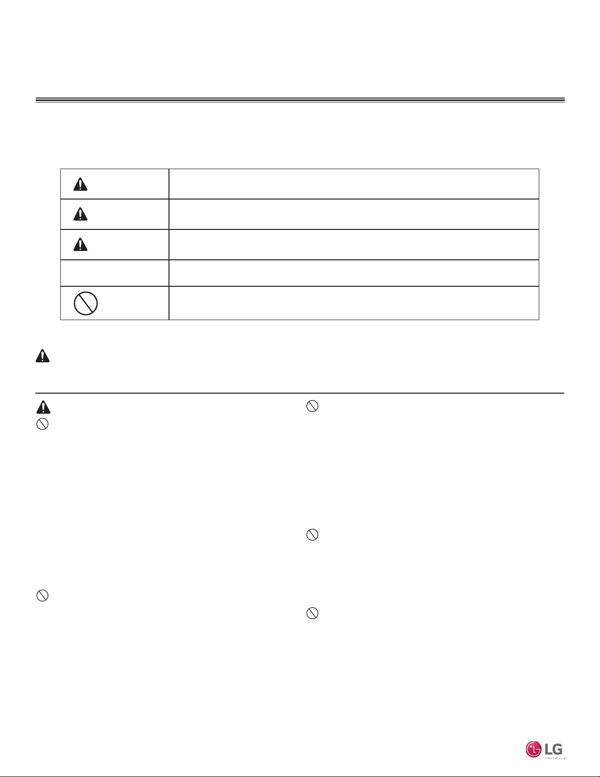
TABLE OF SYMBOLS
This symbol indicates an imminently hazardous situation which, if not avoided, will result in death or
serious injury.
This symbol indicates a potentially hazardous situation which, if not avoided, could result in death or
serious injury.
This symbol indicates a potentially hazardous situation which, if not avoided, may result in minor or
moderate injury.
Note:
This symbol Indicates situations that may result in equipment or property damage accidents only.
This symbol indicates an action that should not be performed.
INSTALLATION
Don’t use or store ammable gas or combustibles near the unit.
There is risk of re, explosion, and physical injury or death.
Do not install, remove, or re-install the unit by yourself
(end-user). Ask the dealer or an LG trained technician to
install the unit.
Improper installation by the user may result in water leakage, re,
explosion, electric shock, physical injury or death.
For replacement of an installed unit, always contact an
LG trained service provider.
There is risk of re, electric shock, explosion, and physical injury or death.
Multi F Standard Wall-Mounted Indoor Unit
The outdoor unit is shipped with refrigerant and the service
valves closed. Do not open service valves on the unit until
all non-condensibles have been removed from the piping
system and authorization has been obtained from the commissioning agent.
There is a risk of physical injury or death.
Do not run the compressor with the service valves
closed.
There is risk of explosion, physical injury, or death.
Periodically check that the outdoor unit is not damaged.
There is risk of explosion, physical injury, or death.
Replace all control box and panel covers.
If cover panels are not installed securely, dust, water and animals may
enter the unit, causing re, electric shock, and physical injury or death.
Always check for system refrigerant leaks after the unit has
been installed or serviced.
Exposure to high concentration levels of refrigerant gas may lead to
illness or death.
4
Do not install the unit using defective hanging, attaching,
or mounting hardware.
There is risk of physical injury or death.
Wear protective gloves when handling equipment.
Sharp edges may cause personal injury.
Dispose of the packing materials safely.
• Packing materials, such as nails and other metal or wooden parts
may cause puncture wounds or other injuries.
• Tear apart and throw away plastic packaging bags so that children
may not play with them and risk suffocation and death.
Do not install the unit in any location exposed to open
ame or extreme heat. Do not touch the unit with wet hands.
There is risk of re, electric shock, explosion, and physical injury or death.
Install the unit considering the potential for earthquakes.
Improper installation may cause the unit to fall, resulting in physical
injury or death.
Do not change the settings of the protection devices.
If the pressure switch, thermal switch, or other protection device is
shorted and forced to operate improperly, or parts other than those
specied by LG are used, there is risk of re, electric shock, explosion,
and physical injury or death.
If the air conditioner is installed in a small space, take measures to prevent the refrigerant concentration from exceeding safety limits in the event of a refrigerant leak.
Consult the latest edition of ASHRAE (American Society of Heating,
Refrigerating, and Air Conditioning Engineers) Standard 15. If the refrigerant leaks and safety limits are exceeded, it could result in personal
injuries or death from oxygen depletion.
Due to our policy of continuous product innovation, some specifications may change without notification.
©LG Electronics U.S.A., Inc., Englewood Cliffs, NJ. All rights reserved. “LG” is a registered trademark of LG Corp.
X
MUL
TI
MUL
F
CAUTION
F
SAFETY INSTRUCTIONS
TI
MA
INSTALLATION – CONTINUED
Be very careful when transporting the product.
• Do not attempt to carry the product without assistance.
• Some products use polypropylene bands for packaging. Do not use polypropylene bands to lift the unit.
• Suspend the unit from the base at specified positions.
• Support the unit at a minimum of four points to avoid slippage from rigging apparatus.
• Failure to follow these directions may result in minor or moderate physical injury.
Note:
Properly insulate all cold surfaces to prevent “sweating.”
Cold surfaces such as uninsulated pipe can generate condensate that may
drip and cause a slippery oor condition and/or water damage to walls.
When installing the unit in a hospital, mechanical room, or
similar electromagnetic eld (EMF) sensitive environment,
provide sufcient protection against electrical noise.
Inverter equipment, power generators, high-frequency medical equipment, or radio communication equipment may cause the air conditioner to
operate improperly. The unit may also affect such equipment by creating
electrical noise that disturbs medical treatment or image broadcasting.
Do not use the product for special purposes such as preserving foods, works of art, wine coolers, or other precision
air conditioning applications. This equipment is designed to
provide comfort cooling and heating.
There is risk of property damage.
Do not make refrigerant substitutions. Use R410A only.
If a different refrigerant is used, or air mixes with original refrigerant, the
unit will malfunction and become damaged.
Do not install the unit in a noise sensitive area.
When connecting refrigerant tubing, remember to allow for
pipe expansion.
Improper piping may cause refrigerant leaks and system malfunction.
Take appropriate actions at the end of HVAC equipment life
to recover, recycle, reclaim or destroy R410A refrigerant according to applicable U.S. Environmental Protection Agency
(EPA) rules.
Periodically check that the outdoor unit is not damaged.
There is a risk of equipment damage.
Install the unit in a safe location where no one can step on or
fall onto it.
attaching, or mounting hardware.
There is risk of unit and property damage.
Install the drain hose to ensure adequate drainage.
There is a risk of water leakage and property damage.
Don’t store or use ammable gas / combustibles near the
unit.
There is risk of product failure.
Always check for system refrigerant leaks after the unit has
been installed or serviced.
Low refrigerant levels may cause product failure
The unit is shipped with refrigerant and the service valves
closed.
non-condensibles have been removed from the piping system and authorization to do so has been obtained from the
commissioning agent.
There is a risk of refrigerant contamination, refrigerant loss and equipment damage.
Do not install the unit with defective hanging,
Do not open service valves on the unit until all
Installation Manual
Due to our policy of continuous product innovation, some specifications may change without notification.
©LG Electronics U.S.A., Inc., Englewood Cliffs, NJ. All rights reserved. “LG” is a registered trademark of LG Corp.
5
X
MUL
MUL
F
SAFETY INSTRUCTIONS
DANGER
WARNING
TI
F
WIRING
High voltage electricity is required to operate this system.
Adhere to the National Electrical Codes and these
instructions when wiring.
Improper connections and inadequate grounding can cause accidental
injury or death.
Always ground the unit following local, state, and National
Electrical Codes.
The information contained in this manual is intended for use
by an experienced, trained electrician familiar with the U.S.
National Electric Code (NEC) who is equipped with the proper
tools and test instruments.
Failure to carefully read and follow all instructions in this manual can
result in equipment malfunction, property damage, personal injury or
death.
Ensure the unit is connected to a dedicated power source
that provides adequate power.
If the power source capacity is inadequate or the electric work is not per-
formed properly, it may result in re, electric shock, physical injury or death.
TI
Turn the power off at the nearest disconnect before servicing
the equipment.
Electric shock can cause physical injury or death.
Properly size all circuit breakers or fuses.
There is risk of re, electric shock, explosion, physical injury or death.
Refer to local, state, and federal codes, and use power wires
of sufcient current capacity and rating.
Wires that are too small may generate heat and cause a re.
Secure all eld wiring connections with appropriate wire
strain relief.
Improperly securing wires will create undue stress on equipment power
lugs. Inadequate connections may generate heat, cause a re and
physical injury or death.
Properly tighten all power connections.
Loose wiring may overheat at connection points, causing a re, physical
injury or death.
MA
Note:
Do not cut, lengthen or shorten the communications and
power cable between any dry contact unit and its connected
indoor unit. Do not install the unit in a location where the communications and power cable cannot be safely and easily connected between the two units. Do not allow strain on this cable.
Poor cable connections can cause equipment malfunction.
Multi F Standard Wall-Mounted Indoor Unit
6
Due to our policy of continuous product innovation, some specifications may change without notification.
©LG Electronics U.S.A., Inc., Englewood Cliffs, NJ. All rights reserved. “LG” is a registered trademark of LG Corp.
X
MUL
TI
MUL
F
DANGER
WARNING
CAUTION
F
SAFETY INSTRUCTIONS
TI
MA
OPERATION
Do not provide power to or operate the unit if it is ooded
or submerged.
There is risk of re, electric shock, physical injury or death.
Use a dedicated power source for this product.
There is risk of re, electric shock, physical injury or death.
Do not operate the disconnect switch with wet hands.
There is risk of re, electric shock, physical injury or death.
Do not allow water, dirt, or animals to enter the unit.
There is risk of unit failure, re, electric shock, physical injury or death.
Avoid excessive cooling and periodically perform ventilation
to the unit.
Inadequate ventilation is a health hazard.
Do not touch refrigerant piping during or after operation.
It can cause burns or frostbite.
Do not operate the unit with the panel(s) or protective
cover(s) removed; keep ngers and clothing away from
moving parts.
The rotating, hot, cold, and high-voltage parts of the unit can cause
physical injury or death.
Periodically check power cable and connection for damage.
Cable must be replaced by the manufacturer, its service agent, or similar
qualied persons in order to avoid physical injury and/or electric shock.
Securely attach the electrical cover to the unit.
Non-secured electrical covers can result in burns or electric shock due to
Periodically verify the hanging bolts and other hardware
securing the unit have not deteriorated.
If the unit falls from its installed location, it can cause property damage,
product failure, physical injury or death.
If refrigerant gas leaks out, ventilate the area before operating the unit.
If the unit is mounted in an enclosed, low-lying, or poorly ventilated area
and the system develops a refrigerant leak, it may cause re, electric
shock, explosion, physical injury or death.
dust or water in the service panel.
Do not open the inlet grille of the unit during operation.
Do not operate the unit with the panels or guards removed.
Do not insert hands or other objects through the inlet or
outlet when the unit is powered. Do not touch the electro-
static lter, if the unit includes one. The unit contains sharp,
rotating, hot, and high voltage parts that can cause personal
injury and/or electric shock.
Ensure no power is connected to the unit other than as
directed in this manual. Remove power from the unit before
removing or servicing the unit.
There is risk of unit failure, re, electric shock, physical injury or death.
Do not open the inlet grille of the unit during operation.
Do not operate the unit with the panels or guards removed.
Do not insert hands or other objects through the inlet or outlet with the unit is plugged in. Do not touch the electrostatic
lter, if the unit includes one.
The unit contains sharp, rotating, hot, and high voltage parts that can
cause personal injury and/or electric shock.
Installation Manual
To avoid physical injury, use caution when cleaning or
servicing the air conditioner.
Note:
Clean up the site after installation is nished, and check
that no metal scraps, screws, or bits of wiring have been left
inside or surrounding the unit.
purpose applications such as preserving foods, works of art,
wine coolers or refrigeration. This equipment is designed to
provide comfort cooling and heating.
Provide power to the compressor crankcase heaters at least
six (6) hours before operation begins.
Starting operation with a cold compressor sump(s) may result in severe
bearing damage to the compressor(s). Keep the power switch on during
the operational season.
Do not use this equipment in mission critical or special-
Due to our policy of continuous product innovation, some specifications may change without notification.
©LG Electronics U.S.A., Inc., Englewood Cliffs, NJ. All rights reserved. “LG” is a registered trademark of LG Corp.
Do not block the inlet or outlet.
Unit may malfunction.
Securely attach the electrical cover to the indoor unit. Non-
secured covers can result in re due to dust or water in the
service panel.
Periodically verify the equipment mounts have not deteriorated.
If the base collapses, the unit could fall and cause property damage or
product failure.
Do not allow water, dirt, or animals to enter the unit.
There is risk of unit failure.
7

X
MUL
TI
MUL
F
F
TI
MA
Multi F Standard Wall-Mounted Indoor Unit
8
Due to our policy of continuous product innovation, some specifications may change without notification.
©LG Electronics U.S.A., Inc., Englewood Cliffs, NJ. All rights reserved. “LG” is a registered trademark of LG Corp.

X
MUL
TI
MUL
F
WARNING
F
INTRODUCTION
TI
MA
Multi F and Multi F MAX Standard
Wall-Mounted Units
This manual describes how to install the LG Multi F and Multi F MAX
(Multi Zone) Standard Wall-Mounted Indoor Units (IDU) for Multi
F heat pump systems. Table 1 lists the available models. Refer to
LG’s Multi F Indoor Unit Engineering Manual for complete detailed
engineering data and selection procedures.
Safety
Safety of personnel is the primary concern during all
procedures. Read and understand the safety summary at the front of this manual. Read and understand
this installation procedure before beginning installation. Use the appropriate tools and accessories
during installation. Plan your work and do not work
alone, if possible. Know how to obtain emergency
medical and firefighting assistance.
Installation Personnel
This equipment is intended for installation by personnel trained
in the required construction, mechanical, electrical, and/or other
disciplines.
Applicable Codes
Personnel must be familiar with and follow the applicable national,
state, and/or local codes.
Figure 1: Typical Multi F Standard Wall-Mounted Indoor Unit
Installation Manual
Installation work must be performed by trained personnel and in
accordance with national wiring standards and all local or other
applicable codes. Improper installation can result in re, electric shock,
physical injury, or death.
Note:
Please read all instructions before installing this product. Become familiar
with the unit’s components and connections, and the order of installation.
Incorrect installation can degrade or prevent proper operation.
Required Tools (field provided)
Required Parts (field provided)
• Level
• Screwdriver
• Electrical lineman pliers
• Electric drill
• Hole saw
• Connecting cable (power and control)
• Pipes - vapor line and liquid line, with
insulation
Due to our policy of continuous product innovation, some specifications may change without notification.
©LG Electronics U.S.A., Inc., Englewood Cliffs, NJ. All rights reserved. “LG” is a registered trademark of LG Corp.
• Drill
• Flaring tool set
• Tubing cutter
• Tube/pipe reamer
• Torque wrenches
• Insulated drain hose
• Additional drain hose
• Allen wrench
• Gas-leak detector
• Thermometer
9
X
MUL
MUL
F
INTRODUCTION
TI
F
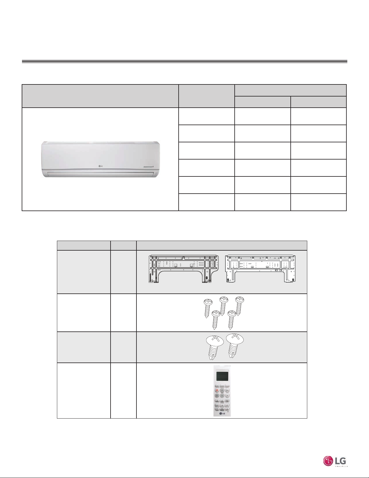
Table 1: Multi F Standard Wall-Mounted Indoor Units
Typical Unit Model Number
LMN078HVT 7,000 8,100
LSN090HSV4 9,000 10,400
LSN120HSV4 12,000 13,800
LMN158HVT 14,300 16,500
LSN180HSV4 18,000 20,800
LMN248HVT 24,000 27,000
TI
Nominal Capacity
Cooling (Btu) Heating (Btu)
MA
Part Quantity Image
Installation Plate One (1)
Type “A” Screws Five (5)
Multi F Standard Wall-Mounted Indoor Unit
Type “B” Screws
(M4 x 12L)
Wireless
Controller with Holder
HVT: AKB73635606
HSV: AKB73835312
Two (2)
One (1)
Table 2: Included Items
7,000 ~ 15,000 Btu/h Indoor Units
18,000 and 24,000 Btu/h Indoor Units
10
Due to our policy of continuous product innovation, some specifications may change without notification.
©LG Electronics U.S.A., Inc., Englewood Cliffs, NJ. All rights reserved. “LG” is a registered trademark of LG Corp.
X
MUL
TI
MUL
F
F
UNIT NOMENCLATURE
TI
MA
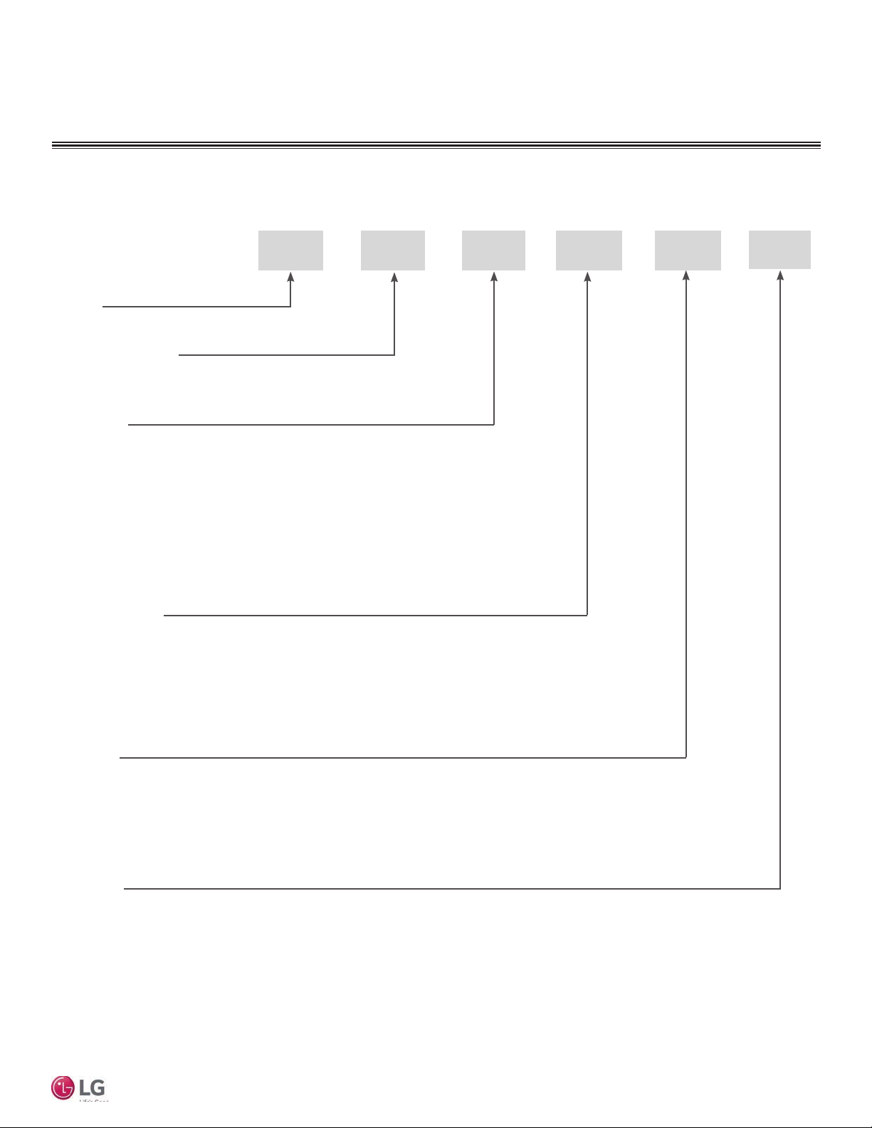
Multi F Multi-Zone Systems — Indoor Units
L
L = LG
Type: M = Multi-Zone
A/S = Single Zone (Gen 4 Single Zone units also compatible with Multi Zone)
Component:
AN: Art Cool™ Wall-Mounted Indoor Unit
N: Standard Wall-Mounted Indoor Unit
CN: Four-Way Ceiling-Cassette Indoor Unit
DN: Ceiling-Concealed Duct (Low Static) Indoor Unit
HN: Ceiling-Concealed Duct (High Static) Indoor Unit
VN: Vertical-Horizontal Air Handling Indoor Unit
M
N 158 HVT
Installation Manual
Nominal Capacity
(Nominal cooling capacity in Btu/h):
078 = 7,000
090 = 9,000
120 = 12,000
Features:
H = Heat Pump
V = Inverter
T = High Wall-Mounted Indoor Unit
P = Art Cool Gallery Indoor Unit
Generation
3 = Third (also Third Gen if no number in this position)
4 = Fourth
• Voltage for all equipment is 208-230V, 60 Hz, 1-phase.
• All indoor units are compatible with wired controllers
158 = 15,000
180 = 18,000
248 = 24,000
Due to our policy of continuous product innovation, some specifications may change without notification.
©LG Electronics U.S.A., Inc., Englewood Cliffs, NJ. All rights reserved. “LG” is a registered trademark of LG Corp.
11
X
MUL
MUL
F
GENERAL DATA
WARNING
TI
F
TI
MA
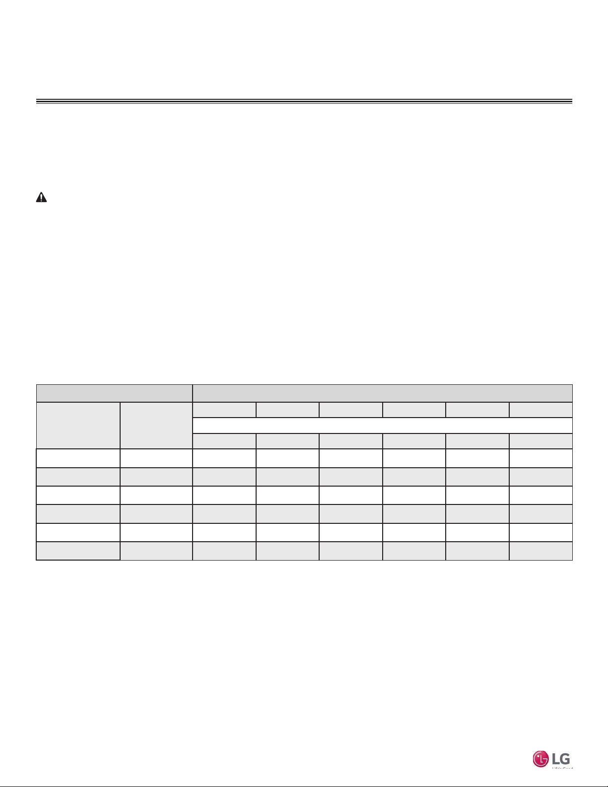
R410A Refrigerant
R410A refrigerant has a higher operating pressure in comparison to R22 refrigerant. All piping system materials installed must have
a higher resisting pressure than the materials traditionally used in R22 systems.
R410A refrigerant is an azeotrope of R32 and R125, mixed at 50:50. The ozone depletion potential (ODP) is 0.
• Do not place refrigerant cylinder in direct sunlight. Refrigerant cylinder may explode causing severe injury or death.
Note
• Because R410A is a combination of R32 and R125, the required additional refrigerant must be charged in its liquid state. If the
refrigerant is charged in its gaseous state, its composition changes and the system will not work properly.
• Do not heat piping more than necessary during installation. Piping may become soft and fail when pressurized.
• Do not use any piping that has not been approved for use in high-pressure refrigerant systems. Piping wall thickness must comply
with the applicable local, state, and federal codes for the 551 psi design pressure of R410A. Inadequate piping may fail when
pressurized.
Allowable Indoor Unit to Outdoor Unit Connections
In Multi F/Multi Zone systems, the standard wall-mounted IDUs can be connected to the Multi F outdoor units (ODUs) listed in Table 3.
Table 3: Allowable Indoor Unit to Outdoor Unit Connections.
Indoor units Outdoor units
Model Number
LMN078HVT 7,000 O O O O O O
LSN090HSV4 9,000 O O O O O O
LSN120HSV4 12,000 O O O O O O
LMN158HVT 15,000 O O O O O O
Indoor Unit Nominal
Capacity (Btu/h)
LMU18CHV LMU24CHV LMU30CHV LMU36CHV LMU480HV LMU540HV
2 3 4 4 8 8
Multi F Standard Wall-Mounted Indoor Unit
LSN180HSV4 18,000 – O O O O O
LMN248HVT 24,000 – O O O O O
connection allowed: O
connection not allowed: –
Device Connection Limitations
• The minimum number of connected and operating indoor units to Multi F / Multi F MAX systems is two.
• The maximum number of indoor units for each Multi F / Multi F MAX heat pump system is:
LMU18CHV = 2 LMU24CHV = 3 LMU30CHV = 4
LMU36CHV = 4 LMU480HV = 8 LMU540HV = 8
Maximum No. of Connectable Indoor Units
• The maximum allowable total indoor unit capacity (Btu/h) for each Multi F / Multi F MAX heat pump system is:
LMU18CHV = 24,000 LMU24CHV = 33,000 LMU30CHV = 40,000
LMU36CHV = 48,000 LMU480HV = 65,000 LMU540HV = 73,000
• Refer to the Multi F Engineering Manual to properly determine total indoor unit connected capacity.
12
Due to our policy of continuous product innovation, some specifications may change without notification.
©LG Electronics U.S.A., Inc., Englewood Cliffs, NJ. All rights reserved. “LG” is a registered trademark of LG Corp.
X
MUL
TI
MUL
F
F
GENERAL DATA
TI
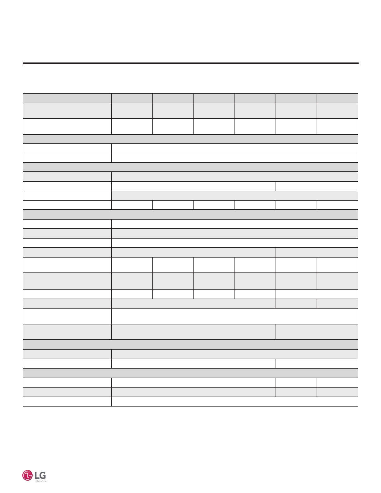
Nominal Cooling Capacity
(Btu/h)
Nominal Heating Capacity
(Btu/h)
Operating Range
Cooling (°F WB)
Heating (°F DB)
Fan
Type
Motor Output (W) x Qty.
Motor/Drive
Airflow Rate CFM (H/M/L)
Unit Data
Refrigerant Type
Refrigerant Control
Power Supply V, Ø, Hz3
Rated Amps (A)
Sound Pressure Level ±3 dB(A)
(H/M/L)4
Dimensions (W x H x D, in.)
Net Unit Weight (lbs.)
Shipping Weight (lbs.)
Power Wiring / Communications
Cable (No. x AWG)5
Heat Exchanger (Row x Column
x Fin / inch) x Number
Pipe Size
Liquid (in.)
Vapor (in.)
Connection Size
Liquid (in.)
Vapor (in.)
Drain O.D. / I.D. (in.)
1
Nominal capacity is rated 0 ft. above sea level with corresponding refrigerant piping
length in accordance with standard length of each outdoor unit and a 0 ft. level difference
between outdoor and indoor units. All capacities are net with a combination ratio between
95 – 105%.
Nominal cooling capacity rating obtained with air entering the indoor unit at 80ºF dry bulb
(DB) and 67ºF wet bulb (WB) and outdoor ambient conditions of 95ºF dry bulb (DB) and
75ºF wet bulb (WB).
Nominal heating capacity rating obtained with air entering the indoor unit at 70ºF dry bulb
(DB) and 60ºF wet bulb (WB) and outdoor ambient conditions of 47ºF dry bulb (DB) and
43ºF wet bulb (WB).
MA
Table 4: Multi F Multi Zone Standard Wall-Mounted Indoor Unit Specications
Model Name LMN078HVT LSN090HSV4 LSN120HSV4 LMN158HVT LSN180HSV4 LMN248HVT
1
1
2
7,000 9,000 12,000 14,300 18,000 24,000
8,100 10,400 13,800 16,500 20,800 27,000
198 / 177 / 162 247 / 230 / 212 335 / 318 / 300 371 / 318 / 247 572 / 501 / 434 720 / 600 / 466
33 / 30 / 26 33 / 30 / 27 39 / 36 / 31 43 / 39 / 34 37 / 33 / 28 42 / 39 / 36
35-1/4 x 11-3/8
x 8-9/32
23 20 20 23 31
Due to our policy of continuous product innovation, some specifications may change without notification.
©LG Electronics U.S.A., Inc., Englewood Cliffs, NJ. All rights reserved. “LG” is a registered trademark of LG Corp.
34-13/16 x 11-1/4
x 8-1/4
(2 x 16 x 23) x 1 (3 x 18 x 22) x 1
Specications
57-77
59-81
Cross Flow
14.4 x 1 76.0 x 1
Brushless Digitally Controlled / Direct
R410A
Electronic Expansion Valve (EEV)
208-230, 1, 60
0.2 0.3
34-13/16 x 11-1/4
x 8-1/4
26 36 37
3/8 1/2
1/4 3/8 1/4
3/8 5/8 1/2
2
This unit comes with a dry helium charge.
3
Acceptable operating voltage: 187V-253V.
4
Sound pressure levels are tested in an anechoic chamber under ISO Standard 3745 and
are the same in both cooling and heating mode. These values can increase due to ambient
conditions during operation.
5
All power wiring / communications cable to be minimum 18 AWG, 4-conductor, stranded,
shielded, and must comply with applicable local and national codes.
35-1/4 x 11-3/8
4 x 18
1/4
27/32, 5/8
x 8-9/32
40-9/16 x 12-13/16
x 9-13/16
40-9/16 x 12-13/16
x 9-13/16
Installation Manual
13
X
MUL
MUL
F
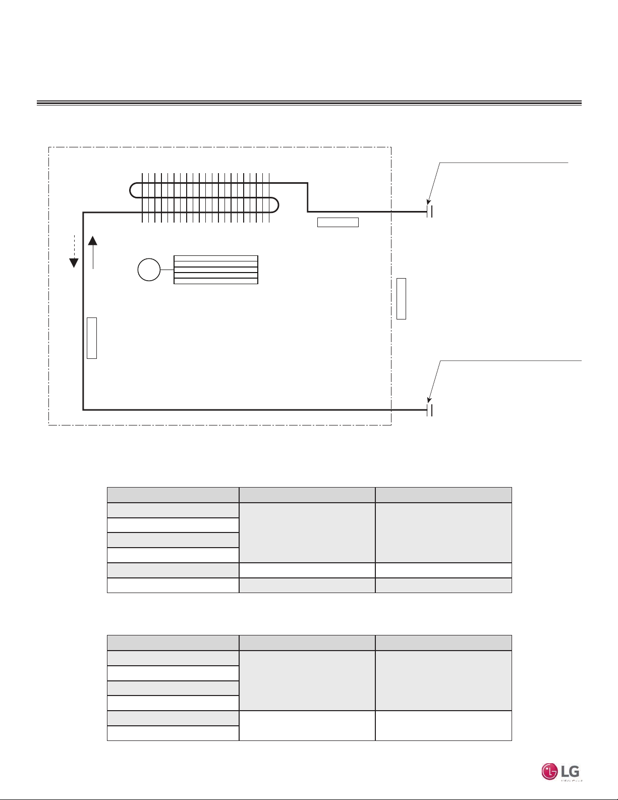
GENERAL DATA
Gas pipe connection port
TI
F
Refrigerant Piping
Cross Flow Fan
Heating
Cooling
Evaporator Inlet Temperature
Thermistor for
M
Heat Exchanger
Thermistor for Evaporator
Outlet Temperature
TI
(flare connection)
Indoor Air Temperature
Thermistor for
Liquid pipe connection port
(flare connection)
MA
Table 5: Multi F Multi Zone Standard Wall-Mounted Indoor Unit Refrigerant Pipe Connection Port Diameters
Multi F Standard Wall-Mounted Indoor Unit
14
Model No. Vapor (inch) Liquid (inch)
LMN078HVT
LSN090HSV4
LSN120HSV4
LMN158HVT
LSN180HSV4 Ø5/8 Ø3/8
LMN248HVT Ø1/2 Ø1/4
Table 6: Multi F Multi Zone Standard Wall-Mounted Indoor Unit Refrigerant Pipe Sizes
Model No. Vapor (inch, OD) Liquid (inch, OD)
LMN078HVT
LSN090HSV4
LSN120HSV4
LMN158HVT
LSN180HSV4
LMN248HVT
Due to our policy of continuous product innovation, some specifications may change without notification.
©LG Electronics U.S.A., Inc., Englewood Cliffs, NJ. All rights reserved. “LG” is a registered trademark of LG Corp.
Ø3/8 Ø1/4
Ø3/8 Ø1/4
Ø1/2 Ø1/4
X
MUL
TI
MUL
F
Max. 49.2 feet
Max. 24.6 feet
A
B
C
D
ODU
F
GENERAL DATA
TI
MA
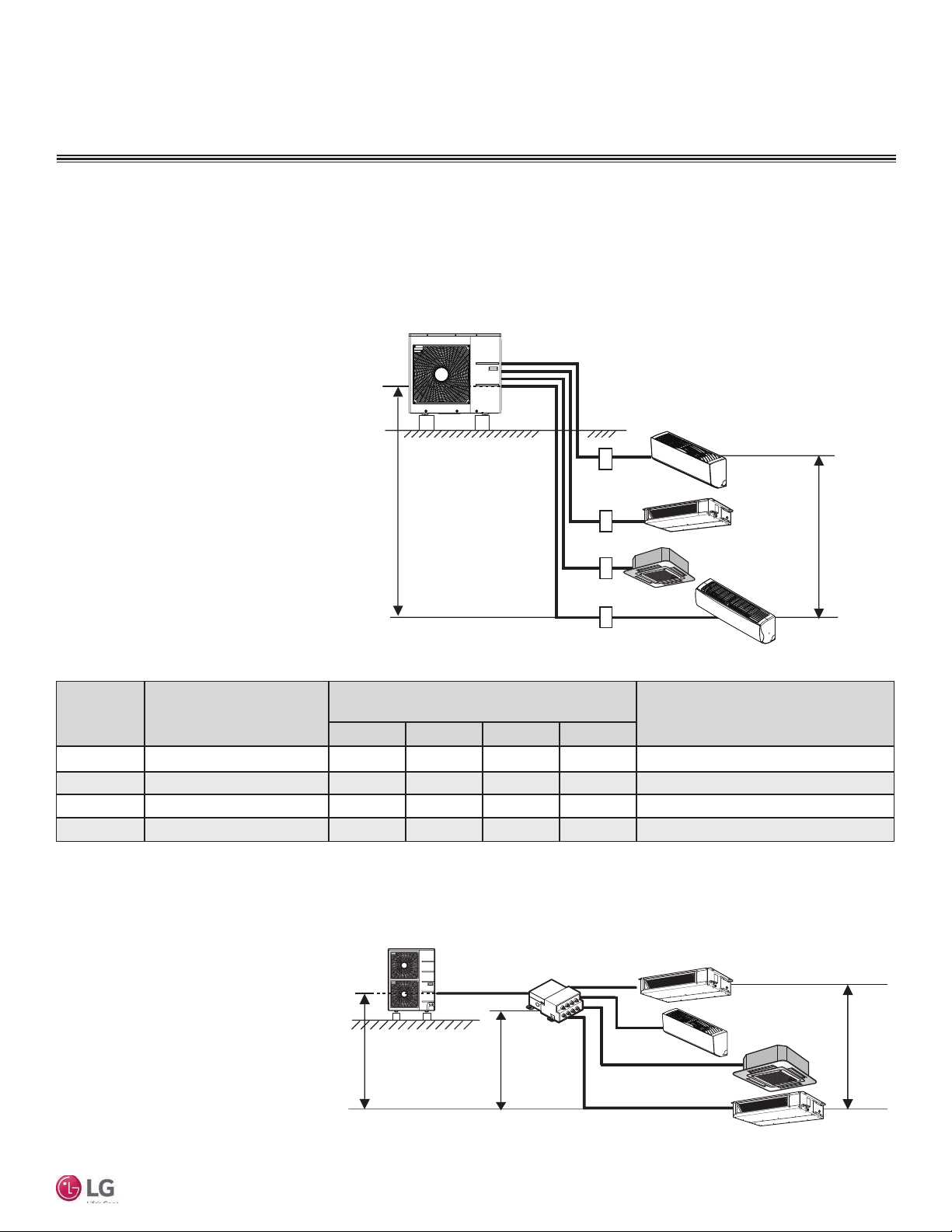
Typical Multi F/Multi F Max Systems
Major System Components
A typical Multi F system consists of an outdoor unit (ODU), refrigerant piping, and two to four indoor units (IDUs). The standard
wall-mounted units described in this manual are one of the types of IDUs that can be connected to a Multi F system.
A typical Multi F Max system consists of an ODU, refrigerant piping, one or two branch distribution units (BDU), and two to eight
IDUs. The standard wall-mounted units described in this manual are one of the types of IDUs that can be connected to a Multi F
Max system.
Typical Multi F System
Example: LMU36CHV outdoor unit with four (4)
indoor units connected.
ODU: Outdoor Unit.
IDU: Indoor Unit.
A, B, C, D: Piping from Outdoor Unit to Indoor Unit.
Installation Manual
Table 7: Multi F Outdoor Unit Refrigerant Piping System Limitations.
Outdoor
Unit
LMU18CHV 9.8 82 82 - - 164
LMU24CHV 9.8 82 82 82 - 246.1
LMU30CHV 9.8 82 82 82 82 246.1
LMU36CHV 9.8 82 82 82 82 246.1
Minimum Length for Each
Pipe Segment (ft.)
Maximum Equivalent Pipe Length
to Each Indoor Unit (ft.)
A B C D
Maximum Equivalent Pipe Length
for Each System (ft.)
Typical Multi F MAX System with One Branch Distribution Unit
Example: LMU540HV outdoor unit with four
(4) indoor units, and one (1) branch distribution unit connected.
ODU: Outdoor Unit.
IDU: Indoor Unit.
BDU: Branch Distribution Unit.
A: Main Piping.
B: Branch Piping (Branch Distribution Unit to
Indoor Unit[s]).
Due to our policy of continuous product innovation, some specifications may change without notification.
©LG Electronics U.S.A., Inc., Englewood Cliffs, NJ. All rights reserved. “LG” is a registered trademark of LG Corp.
h1 ≤ 98.4 feet
A
BDU
h3 ≤ 32.8 feet
IDU
B
B
B
B
IDU
h2 ≤ 49.2 feet
IDU
IDU
15
X
MUL
MUL
F
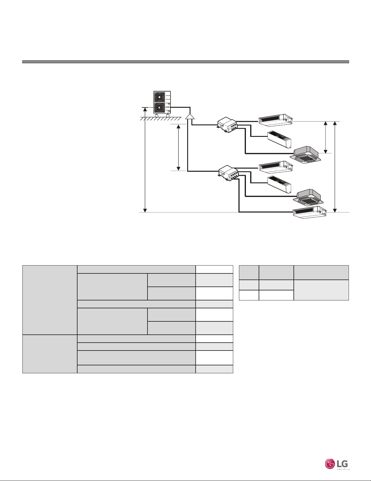
GENERAL DATA
ODU
TI
F
Typical Multi F/Multi F Max Systems
Typical Multi F MAX System with Two Branch Distribution Units
Example: LMU540HV outdoor unit with seven
(7) indoor units, and two (2) branch distribution units connected.
ODU: Outdoor Unit.
IDU: Indoor Unit.
BD: Branch Distribution Unit(s).
ΣA: Main Piping.
ΣB: Branch Piping (Branch Distribution Unit[s]
to Indoor Unit[s]).
h4 ≤ 49.2 feet
h1 ≤ 98.4 feet
A
BDU Y-Branch
A
A
BDU
B
B
B
B
B
B
B
IDU
IDU
IDU
IDU
TI
IDU
IDU
MA
h3 ≤ 32.8 feet
h2 ≤ 49.2 feet
Table 8: Multi F MAX Outdoor Unit Refrigerant Piping System Limitations.
Pipe Length
(ELF = Equivalent
Length of pipe
in Feet)
Multi F Standard Wall-Mounted Indoor Unit
Elevation Differential
(All Elevation
Limitations are
Measured in
Actual Feet)
(Outdoor Unit to Branch
Distribution Units: ΣA)
(Branch Distribution Units
to Indoor Units: B)
If outdoor unit is above or below indoor unit (h1)
Between the farthest two indoor units (h2)
Between branch distribution unit and farthest
Between branch distribution units (h4)
Total piping length (ΣA + ΣB)
Main pipe
Total branch piping length (ΣB)
Branch pipe
connected indoor unit(s) (h3)
Minimum
Maximum
Minimum
Maximum
≤475.7 feet
9.8 feet
≤180.4 feet
≤295.3 feet
9.8 feet
≤49.2 feet
≤98.4 feet
≤42.9 feet
≤32.8 feet
≤42.9 feet
Table 9: Multi F MAX Piping Sizes.
Piping
Liquid Ø3/8
Main Pipe A
(inch)
Gas Ø3/4
Depends on the size
of the indoor unit piping
IDU
Branch Pipe B
16
Due to our policy of continuous product innovation, some specifications may change without notification.
©LG Electronics U.S.A., Inc., Englewood Cliffs, NJ. All rights reserved. “LG” is a registered trademark of LG Corp.
X
MUL
TI
MUL
F
F
GENERAL DATA
TI
MA
Refrigerant Piping Requirements
Field Supplied Refrigerant Piping
Type ACR copper is the only approved refrigerant pipe material for use with LG Multi F air conditioning
products. ACR rated tubing is the only type that ships with yellow caps. Approved tubing for use with
Multi V products will be marked “R410 RATED” along the length of the tube. Tube wall thickness should
meet local code requirements and be approved for a maximum operating pressure of 551 psi.
Refer to the refrigerant piping section (starting on page 22) of the General Installation Guidelines for
more information on piping.
Using Refrigerant Components
Field-supplied elbows are allowed if they are long radius and designed for use with R410A refrigerant. Be
sure to account for the additional pressure losses in equivalent pipe length calculations for each elbow,
y-branch, and branch distribution unit. The equivalent pipe length of each elbow, Y-branch, and/or branch
distribution unit must be added to each pipe segment to ensure maximum lengths are not exceeded.
Table 10: Equivalent Piping Length for Elbows,
Y-branches, and Branch Distribution Units.
Component
Size (Inches)
1/4 3/8 1/2 5/8 3/4
Installation Manual
Elbow (ft.)
Y-Branch Kit (ft.)
(Multi F MAX systems only)
Branch Distribution Unit (ft.)
(Multi F MAX systems only)
1
Kit contains two Y-branches: one for liquid and one for vapor.
0.5 0.6 0.7 0.8 1.2
1
1.6
8.2
Due to our policy of continuous product innovation, some specifications may change without notification.
©LG Electronics U.S.A., Inc., Englewood Cliffs, NJ. All rights reserved. “LG” is a registered trademark of LG Corp.
17
 Loading...